
Recommended
More Related Content
What's hot
What's hot (20)
Viewers also liked
Viewers also liked (20)
Similar to CCNA Packet Tracer 1.6.1
Similar to CCNA Packet Tracer 1.6.1 (20)
More from Rafat Khandaker
More from Rafat Khandaker (10)
Recently uploaded
Recently uploaded (20)
CCNA Packet Tracer 1.6.1
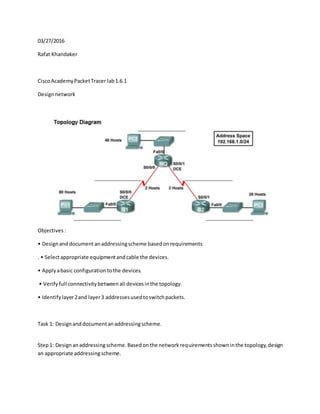
- 1. Rafat Khandaker PACKET TRACER 1.6.1 LAB 03/29/2016 Design network Objectives: • Designanddocumentanaddressingscheme basedonrequirements . • Selectappropriate equipmentandcable the devices. • Applyabasic configurationtothe devices. • Verifyfull connectivitybetweenall devicesinthe topology. • Identifylayer2and layer3 addressesusedtoswitchpackets. Task 1: Designanddocumentanaddressingscheme. Step1: Designanaddressingscheme.Basedonthe networkrequirementsshowninthe topology,design an appropriate addressingscheme. • Startingwiththe largestLAN,determinethe size of eachsubnetyouwill needforthe givenhost requirement.
- 2. In thisnetwork,Iplanon usingthe private IPspace to it'smaximumefficiency.Inoticedwe Have a total of 140 pc hosts with3 Routerinterface with3 switches,creatingatotal of 140+6 or more IP addresses. Planfor B1 : 80 hostsare neededusingclassCsubnet. 2^6 < 80 < 2^7 where lastoctet2^7 = 128 We can give B1 7 bitsfor host,leaving1bitfor subnet. mask= 255.255.255.128 Leavinguswithhostaddressspace ( 192.168.1.1 - 192.168.1.126 ) Subnet(192.168.1.0) withBroadcast (192.168.1.127) Planfor B2 20 hostsneeded. 2^4 < 20 < 2^5 5 hostbitswith3 subnetbits. mask= 255.255.255.224 Hosts ' cannot be "lastoctet" = ( 1-127 ) 192.168.1.128 = new subnetforB2 Hosts :128 +32 = 160 hostaddressrange ( 192.168.1.129 - 192.168.1.160 ) Subnet(128) withbroadcastat (159) Planfor HQ 40 hosts need2^6 = 64 At-least6bitsare neededforhostaddress,leaving2bitsfor subnet Mask = 255.255.255.192 Host addresscannotoccupy previousdesignsforB1and B2 ( 192.168.1.0 to 192.168.1.160 ) Start addresshasto be multiple of 64= 192.168.1.192 Host addressrange ( 192.168.1.193 - 192.168.1.254 ) Broadcast address= 192.168.1.255
- 3. Note that Addressspace 160 – 192 are notin use ( Reserve serial interfaces) • Afterthe addresseshave beendeterminedforall the LAN subnets,assignthe firstavailableaddress space to the WAN linkbetweenB1and HQ.assignaddressspace tothe WAN linkbetweenHQandB2. NETWORK192.168.1.164/30 CIDR30 = 255.255.255.252 2 hostsper network broadcast= 192.168.1.167 nextnetwork=192.168.1.168 w/broadcast at 192.168.1.171 Serial interface HQ= s2/0 192.168.1.165 ; s3/0 192.168.1.169 255.255.255.252 *I didnot use the firstavailable ipaddresswhichwas..161.. Inlast octet..* note B1= s2/0 192.168.1.166 at HQ s2/0 192.168.1.166 B2= s3/0 192.168.1.170 at HQ s3/0 192.168.1.169 Device Interface IP address Subnet Mask Default GW Fa0/0 192.168.1.193 255.255.255.192 Routerinterface HQ S2/0 192.168.1.165 255.255.255.252 Routerinterface S3/0 192.168.1.169 255.255.255.252 Routerinterface B1 Fa0/0 192.168.1.1 255.255.255.128 Routerinterface S2/0 192.168.1.166 255.255.255.252 Routerinterface B2 Fa0/0 192.168.1.129 255.255.255.224 Routerinterface S3/0 192.168.1.170 255.255.255.252 Routerinterface PC0 NIC 192.168.1.2 - 126 255.255.255.128 192.168.1.1 PC1 NIC 192.168.1.194 - 254 255.255.255.192 192.168.1.193 PC2 NIC 192.168.1.130 - 158 255.255.255.128 192.168.1.129 Step2: Documentthe addressingscheme.•Use the blankspaceson the topologytorecord the network addressesindotted-decimal/slashformat.•Use the table providedinthe printedinstructionsto documentthe IPaddresses,subnetmasksanddefaultgatewayaddresses. Forthe LANs,assignthe first IP addresstothe router interface.Assignthe lastIPaddresstothe PC Forthe WAN links,assignthe first IP addresstoHQ.
- 4. Task 2: Selectequipmentandcable devices. Step1: Selectthe necessaryequipment.Selectthe remainingdevicesyouwillneedandadd themto the workingspace inside PacketTracer.Use the labelsasa guide asto where toplace the devices. Step2: Finishcablingthe devices.Cablethe networksaccordingtothe topologytakingcare that interfacesmatchyourdocumentationinTask1. Task 3: Applyabasic configuration. Step1: Configure the routers.Usingyourdocumentation,configure the routerswithbasic configurationsincludingaddressing.Use ciscoasthe line passwordsandclassas the secret password.Use 64000 as the clockrate. Step2: Configure the PCs.Usingyourdocumentation,configure the PCswithanIPaddress, subnetmask,anddefaultgateway. Task Packet Tracer Simulation ( after configuration )
- 5. Configuring Router HQ NOTE AND IGNORE THE SERIAL INTERFACE* THEY HAVE BEEN PROPERLY ASSIGNED IN THE REAL PACKET TRACER ! *** Simplyconfigure RouterHQwithbasichostname,banner,password.Also,configure fastethernet interface withipaddressIcalculatedattable.Make sure the interface isinnoshutdownmode.We can see that the linkstate isgreen.
- 6. This portion of the command line, I configured the serial interfaces for the WAN port and also synced withthe DCE clock rate of 64000, as documentedby the lab requirements for part 2. Also made sure to configure each interface to no shutdown. Last but not least, made sure to copy the running config to start-up config so the router will boot with the configuration changes. * also forgot to enable secret class on configuration settings Copy running-config to startup-config and reload the router
- 7. RESULT OF SHOW RUN FROMHQ
- 9. Router B1
- 11. Notice that the DCE interface did not show message when configuring clock rate. This is most likely because I connected the B1 router to supply clock rate to Router HQ through the serial interface. Configure Router B2 After configuring B2, this is the show run status
- 13. I noticed that the link for s3/0 was not configured properly after I entered no shutdown command for s2/0 on B2. Fix After assigning s3/0 on router HQ with IP address, clock rate and no shutdown . I was able to achieve connection green. Packet Tracer Simulation Network
- 14. Take notice here that all the links are green, meaning that the link state are in UP state, However for the next portion of this lab i noticed that I have no layer 3 connectivity between the WAN links; this is mostlikely due to packet tracer lab 1.6.1 assumption that the RIP protocol is administered by default. This is not true for for this situation, I will have to enable RIP protocol. Assign RIP v 2 for router B1 / B2 / HQ
- 15. Task 4: Test connectivity and examine the configuration. In the last step I troubleshootedthe networkwithaseriesof pingrequestfromthe hostsineachsubnet. HOST to defaultgateway, hosttonextrouteronhop and hostto host connectivity. I noticedthatI didnot have connectivitybetweenroutertorouterandhost past the defaultgateway. I knewthatthe problemhadtobe onthe routerconfiguration.
- 16. Packettracer 1.6.1 labassumesthat ripv 2 isa protocal that hasalreadybeenpreconfigured.Inmy case,configuringthe Packettracerfromscratch, it has notbeenconfigured. aftertroubleshootingthe ripprotocal,i noticedthatthe routingtable didnothave the rip v2 update.
- 17. so to enable the update i hadto assignthe networkvalue tocommunicate the update. IOS TERMINAL we can see that RIPv2 didnotexchange routingupdates I DID THIS FOR ALL ROUTERS ON THE NETWORK ANDACHIEVEDFULL CONNECTIVITY Assignroutingripv 2 withthe networkto exchange update information aftertroubleshootingi have full connectivitybetweenall hostfrom192.168.1.126
- 20. ALL HOSTS ACROSSTHE NETWORKCAN BE PINGEDFROM192.168.1.126 CONCLUSION: I have completedthe packettracer1.6.1 lab.In thislabI have implementedthe subnettheoryand routingprotocal to communicate informationacrossnetworktopology.Ihave constructedasimulation to testand troubleshootconnectivity.Ihave successfulyusedthe troubleshootingprocedure to complete all linkfailures.Ilearnedhowtodesignroutertorouternetworkdesignandsubnet implementation.
- 21. CREATED BY RAFATKHANDAKER YOUTUBE PACKTTRACER 1.6.1 lab withcommentary: https://youtu.be/Mrcl5N0n5kY by Rafat Khandaker THANK YOU