Energy saving in urea plant by modification in heat exchanger and process

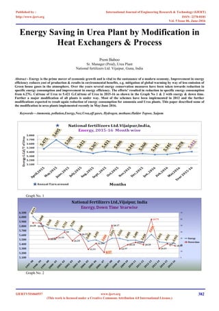
Energy is the prime mover of economic growth and is vital to the sustenance of a modern economy. Improvement in energy efficiency reduces cost of production & results in environmental benefits, e.g. mitigation of global warming by way of less emission of Green house gases in the atmosphere. Over the years several energy conservation measures have been taken towards reduction in specific energy consumption and improvement in energy efficiency. The efforts’ resulted in reduction in specific energy consumption from 6.27G. Cal/tone of Urea to 5.421 G.Cal/tone of Urea in 2015-16 as shown in the Graph No 1 & 2 with energy & down time. Further a major modification of all plants is under way. Most of the schemes have been implemented in 2012 and the further modifications expected to result again reduction of energy consumption for ammonia and Urea plants. This paper described some of the modification in urea plants implemented recently in May/June 2016.

Recommended
More Related Content
What's hot
What's hot (20)
Viewers also liked
Viewers also liked (20)
Similar to Energy saving in urea plant by modification in heat exchanger and process
Similar to Energy saving in urea plant by modification in heat exchanger and process (20)
More from Prem Baboo
More from Prem Baboo (20)
Recently uploaded
Recently uploaded (20)
Energy saving in urea plant by modification in heat exchanger and process
- 1. Energy Saving in Urea Plant by Modification in Heat Exchangers & Process Prem Baboo Sr. Manager (Prod), Urea Plant National fertilizers Ltd. Vijaipur, Guna, India Abstract - Energy is the prime mover of economic growth and is vital to the sustenance of a modern economy. Improvement in energy efficiency reduces cost of production & results in environmental benefits, e.g. mitigation of global warming by way of less emission of Green house gases in the atmosphere. Over the years several energy conservation measures have been taken towards reduction in specific energy consumption and improvement in energy efficiency. The efforts’ resulted in reduction in specific energy consumption from 6.27G. Cal/tone of Urea to 5.421 G.Cal/tone of Urea in 2015-16 as shown in the Graph No 1 & 2 with energy & down time. Further a major modification of all plants is under way. Most of the schemes have been implemented in 2012 and the further modifications expected to result again reduction of energy consumption for ammonia and Urea plants. This paper described some of the modification in urea plants implemented recently in May/June 2016. Keywords—Ammonia, pollution,Energy,Nox;Urea,off gases, Hydrogen, methane.Haldor Topsoe, Saipem Graph No. 1 Graph No. 2 International Journal of Engineering Research & Technology (IJERT) ISSN: 2278-0181http://www.ijert.org IJERTV5IS060557 (This work is licensed under a Creative Commons Attribution 4.0 International License.) Published by : Vol. 5 Issue 06, June-2016 www.ijert.org 382
- 2. INTRODUCTION The National Fertilizers Ltd. Vijaipur is located in Madhya Pradesh (India). The Plant have two ammonia plant M/S. Haldor Topsoe Technology, Denmark capacity 1750 & 1864 TPD for line-I & line-II respectively and four urea plant of M/S. Saipem ammonia stripping process, Italy . The line-I plant installed in 1988 and that of line –II in 1997.The capacity of Urea-I urea –II is 3030 & 3231 TPD respectively. The raw material used includes natural gas, Naphtha, water and power. Three Numbers Captive power plant of capacity 17 X 3 MW are used in this complex. The national Fertilizers contribute 16 % to India’s total urea production. The technology used to produced ammonia and urea has been revamped over the years and won the managements numerous productivity excellence awards and accolades. The innovative and indigenously developed project “utilization of “C-3 off gas” from urea plant as supplementary fuel in heat recovery unit of captive power plant. The C-3 is the vessel in urea plant final stage of Medium pressure section where inerts gases including Hydrogen, Methane, Nitrogen and oxygen & argon are vented. Process of Vijaipur Plant The process of Vijaipur followed for synthesis of the ammonia is hydro desulfurization primary reforming secondary reforming, CO shift converter, CO2 absorption and regeneration in GV (Giamarco- Vetrocock Section), Methanation-ammonia synthesis. The urea synthesis process follows High pressure CO2 compressor and liquid ammonia pumping high pressure and stripping medium and low pressure ammonium carbamate decomposition. Ammonium recovery and recycles two stage vacuum concentration with one additional stage of Preconcentrator. The effluent generated in urea plant is treated in waste water treatment section and treated process condensate is sent to the demineralized water plant for recycling after polish water unit. 1. MODIFICATION IN HEAT EXCHANGER (E-11) DESCRIPTION:- In Urea plant, C-3 off gases from medium pressure section is being vented continuously to control the loop pressure. Each stream of Urea Plant generates around 700 -800 Nm³/h of C-3 off gases, so total generation of C-3 off gases is around 2800 Nm³/h. C-3 off gas comprises Hydrogen, Methane, Ammonia, Nitrogen & Oxygen in the ratio of 25- 30%, 7-10%, 2.5-12%, 50-55% & 6-10% respectively. Considering the heating value of C-3 off gases, it has been utilized these gases in HRU-I &II as supplementary fuel. MP inerts washing tower absorbs ammonia from it’s inlet vapour comprising of inerts such as hydrogen, methane argon nitrogen & oxygen in three numbers of valve trays fitted at the top of the E-11 which is called as C-03 cold condensate at 40 0 C of about 0.5 -0.8 m3 /hr. is being used as absorbent which is being introduced at the top of the valve tray tower(C-3). The some amount (30-50 sm3 /hr) of natural gas feed in inlet of medium pressure condenser (E-7) to avoid explosive mixture in exit of control valve because the oxygen about 8-10 % present in gases mixture. The heat of absorption for formation of ammonical solution is being taken out through vertically installed cooling water exchanger E-11 for better heat transfer by forming falling film; E-11 has been equipped with ferrules at top having 02 numbers tangential hole of 1.5 mm dia hole. Ammonical solution while falling down through heat exchanger (E-11) gets cooled after exchanger heat with cooling water up to about 430 C and recycles back into the upstream equipment as economy of the process. Inerts along with residual ammonia was being vented to top of the prilling tower through 31/41 PV 108 and this removal of inerts are required to maintain MP loop pressure at desired range. This inerts gases along with residual ammonia is called C-3 off gas having lower calorific value in the range of 1500 Kcal/nm3 . Since commissioning of urea-II plant, C-3 off gas comprising of about 4-5% of ammonia was vented to atmosphere through prilling tower top stack continuously with flow of about 600-800 nm3 /hr. from each stream of urea-II. In 2012 these gases had been lined to HRU in CPP for recovers its energy. However line-I ammonia in off gasses are 0.5-1.2 %, In line-II plant this figure is more than line-I so the minor modification has been done to improved efficiency of heat exchanger E-11. However since October 2012, modification has been carried out for utilization of C-3 off gas as supplementary fuel in CPP HRSG burners as this gas having significant calorific value. This modification became successful with saving 2.8 G.cal /hr. resulted in financial saving of `5.00 crore. Further during capacity enhancement project of urea-II plant, process Licenser M/S. Saipem had recommended certain modification for the vapour inlet nozzle of 31/41 E-11/C-3 and the same modification, vapour inlet nozzle has been extended up to minimum bottom level of C-3/E-11 bottom solution holder from its original location of the equipment weld neck flange position. After implementation the modification proposed by process licenser in July 2012, C-3 off gas ammonia content reduced drastically from 4-6 to 3-5 % in urea-II plant. Off gas is being used as supplementary fuel in CPP HRSG burner with flow of about 600-900 nm3 /hr. from each stream with ammonia contents of 3-6 % giving higher NOx level in the flue gases of CPP, HRSG. In May 2016 shut down cooling water exchanger of MP Inerts washing tower (E-11) has been modified by plugging about 110 peripheral tubes at top only with press fitted Teflon plug as shown in the attached photograph in figure No.1. Further one SS plate has been welded to retain the press fitted plug at its position firmly. After implementation of this modification ammonia contents in C-3 off gas has been come down to 1-2 % .Matter has been taken up with M/S Saipem & process Licenser has been agreed for proposed modification for plugging of E-11 peripheral tubes. The water contents 0.5-0.8 m3/hr is the very less quantity within 400 tubes the film in heat exchanger was not made, also the sufficient hold up level up to ferrules tangential holes on tube sheet, now the 27 % tubes has been plugged and now no problem in heat exchanger heat transfer. International Journal of Engineering Research & Technology (IJERT) ISSN: 2278-0181http://www.ijert.org IJERTV5IS060557 (This work is licensed under a Creative Commons Attribution 4.0 International License.) Published by : Vol. 5 Issue 06, June-2016 www.ijert.org 383
- 3. Analysis of C-3(off Gas) before modification (Date 13/04/2016.) C-3 Off gas Analysis Unit NH3 H2 Ar+O2 CH4 N2 Total 31 4.00 25.60 11.90 10.90 47.60 100 41 5.80 24.76 11.12 10.12 48.20 100 Table No. 1 Analysis of C-3(off Gas) after modification (Date 08/06/2016) Unit NH3 H2 Ar+O2 CH4 N2 Total 31 1.20 24.93 13.97 11.84 48.06 100 41 1.89 28.0 11.50 10.01 48.6 100 Table No -2 Figure No. 1 Benefits from this Modification 1. About 1.160 ton ammonia saved per day from 31/41 streams and annually saving 383 Ton, in terms of urea 666 ton per year saving. 2. NOx control in CPP HRU exhaust. International Journal of Engineering Research & Technology (IJERT) ISSN: 2278-0181http://www.ijert.org IJERTV5IS060557 (This work is licensed under a Creative Commons Attribution 4.0 International License.) Published by : Vol. 5 Issue 06, June-2016 www.ijert.org 384
- 4. Table No.-3 2. MODIFICATION IN PROCESS (Diversion of MP aqueous ammonia solution to LP section Condenser) I. There are two options (With running of the aqueous ammonia pump) Partially or fully utilise this aqueous ammonia solution in E-8(Low pressure condenser) inlet line along with P-15 A/B discharge (from waste water section) for absorption of gases coming from LP decomposer. For this ½” tapping from drain downstream of 31/41 LV-103 (P-7A/B discharge) has been taken and injected just of ½ “ E-8 inlet line. This modification helping in reducing the temperature of top of C-1(MP Absorber) and also helping the controlling LP pressure, The cold water to C-4(low pressure inerts tower) now reduced to zero. The modified flow diagram as shown in the figure No. -2 International Journal of Engineering Research & Technology (IJERT) ISSN: 2278-0181http://www.ijert.org IJERTV5IS060557 (This work is licensed under a Creative Commons Attribution 4.0 International License.) Published by : Vol. 5 Issue 06, June-2016 www.ijert.org 385
- 5. Figure No -2 II. without running of the aqueous ammonia pump the solution transfer with differential pressure- In this case the motor stopped and suction /discharge valve of the pump must be opened the solution transferred by differential of Low Pressure & Medium Pressure, or pump can be removed, suction & discharge lines connected to each other’s. Following advantages with this modification 1. Reflux to C-1(medium pressure absorber) Reduced by 2.0 m3 /hr. 2. Additional water to C-4(low pressure inerts washing column) now fully stopped. 3. No limitation to increase the water flow to C-3(medium pressure inerts washing column) to minimize ammonia losses. 4. Ammonia drastically reduced in C-3 (medium pressure inerts washing column) off gas. 5. Low Pressure section pressure easily controlled and water reduced in C-4(low pressure inerts washing column) 6. Power saving in one stream=VI Cos ø X √3 =440 X15 X 0.9=10288 W =10.288 KWH and for both streams 2 X 10.288 KWH =20.567 KWH, Now Annually saving 180245.8 KWH, in Currency Rupees = `901229 ($ 13665). 3. MODIFICATION IN STRIPPER FERRULES:- Four nos. strippers have been provided (one each in11, 21, 31 & 41 stream) in urea-I & Urea-II plants for removal of excess NH3 & unreacted CO2 from the reactor outlet effluent. The strippers are of L&T make and have been provided with 1677 nos. male type ferrules having 2.8 mm dia. Three nos. tangential holes for uniform distribution of influent Urea + Carbamate stream as thin film inside bimetallic tubes. Original ferrules have been provided with two step transition piece protruding inside the bimetallic tubes to facilitate formation of thin & uniform liquid film. Problem of erratic behaviour of strippers was being noticed, whereupon during load change/after start-up/ high load operation, stripper top temperature used to increase while bottom temperature was found to decrease vis-à-vis recommended operating limits in spite of pushing max possible amount of steam through PV-14 (steam to E-1) valve. Above phenomenon not only resulted in reduced stripper efficiency thereby putting load on downstream units but also caused load limitation on no. of occasions during high load plant operation. In view of foregoing, feedback was obtained from other similar plant operators & M/S Saipem so as to find out ways & means to tide over the problem. International Journal of Engineering Research & Technology (IJERT) ISSN: 2278-0181http://www.ijert.org IJERTV5IS060557 (This work is licensed under a Creative Commons Attribution 4.0 International License.) Published by : Vol. 5 Issue 06, June-2016 www.ijert.org 386
- 6. Root cause of the problem, as found out in-house Deterioration in respect of size & shape of tangential holes 1. Erosion/corrosion of bottom most transition piece of the ferrules. 2. The tangential hole dia of stripper is less than required. Same resulted into improper liquid distribution & erratic behaviour of the stripper. In view of foregoing & on the basis of recommendation by M/S Saipem; it was decided to part replace existing ferrules with modified ones having 3.2 mm dia. Tangential holes & single step transition piece in all the line –I & line-II stream. During April, 09 and May 2010 shutdown all the ferrules of line-II were replaced with modified total 1677 nos. in all stripper31/41 stream. 11/21 stripper ferrules have been also modified in April 2016 shut down the same as line-II stripper as shown in the figure No. 3 , 4& 5 .Observations made w.r.t. 11/21 stripper performance before & after change out of ferrules are table No-4 Sr.No. Parameters Before S/D 16/03/2016 After /D. 13/06/2016 11 stream 21 stream 11 stream 21 Stream 1 Stripper Top Temp.,0 C 195.1 194.7 191.4 190.3 2 Stripper bottom Temp., 0 C 203.2 203.1 206.3 206.7 3 Steam to stripper Pressure Kg/cm2 24.5 24.2 21.25 21.57 Table No-4 As we can see from the tabulated data that although stripper top temperature is being obtained on the lower side there is no limitation in achieving stripper bottom temperature at reduced MS steam pressure & the behaviour of the stripper is stable. Thus additional operating margin is now available for increasing plant load (PV-14(steam to stripper) opening 50-55%) Physical condition of replaced original ferrules indicate severe erosion/Corrosion in the II step of the ferrules & irregular enlargement of hole dia. Benefits of Stripper ferrules modification 1. Bottom temperature of stripper achieved at low steam pressure. 2. Top temperature reduced 1900 C from 195 0 C 3. Now available ∆T across top & bottom is 160 C , before modification it was only 80 C 4. No erratic behaviour observed. International Journal of Engineering Research & Technology (IJERT) ISSN: 2278-0181http://www.ijert.org IJERTV5IS060557 (This work is licensed under a Creative Commons Attribution 4.0 International License.) Published by : Vol. 5 Issue 06, June-2016 www.ijert.org 387
- 7. Fig. No-3 Fig. No.-4 International Journal of Engineering Research & Technology (IJERT) ISSN: 2278-0181http://www.ijert.org IJERTV5IS060557 (This work is licensed under a Creative Commons Attribution 4.0 International License.) Published by : Vol. 5 Issue 06, June-2016 www.ijert.org 388
- 8. Fig. No. 5 CONCLUSION N.F.L.Vijaipur is very much committed to Energy management. Considering that Fertilizer manufacturing is an energy intensive process, we have realized that a small step towards within the premises of NFL shall be a great leap in the energy front of the Country and shall help in materializing the Targets. The National Fertilizers Ltd, Vijaipur has always made consistent Endeavour’s and efforts’ towards energy conservation and continual improvement in the direction of energy reduction and improvement in the direction of energy reduction and improvement in energy efficiency. The line-I and line-II plants have been revamped in 2012.After revamp the significant reduction of energy have been noticed. After the implementation of above modification in equipments and process the significant energy has been saved and also controls NOx in HRU exhaust in captive power plant. Acknowledgement I express sincere thanks to Mr. R.K. Chopra, General Manager, National Fertilizers Ltd., Vijaipur Unit, for his support and guidance in carrying out this modification & study. REFERENCES Data taken from own N.F.L laboratory Legends LP- Low Pressure MP- medium Pressure, LS- Low pressure steam MS- Medium Pressure Steam. SS-Stain less steel (SS 316) G. cal-Giga Calorie CPP-captive power plant HRSG-heat recovery steam generation HRU-Heat recovery unit INR-Indian Rupees International Journal of Engineering Research & Technology (IJERT) ISSN: 2278-0181http://www.ijert.org IJERTV5IS060557 (This work is licensed under a Creative Commons Attribution 4.0 International License.) Published by : Vol. 5 Issue 06, June-2016 www.ijert.org 389