Electronic devices_DPP
•
0 likes•8 views

Daily Practice Paper_ Electronic Devices for JEE Main and NEET Candidates_For CBSE/ICSE and other state board students.

Recommended
More Related Content
What's hot
What's hot (18)
Similar to Electronic devices_DPP
Similar to Electronic devices_DPP (17)
Recently uploaded
Recently uploaded (20)
Electronic devices_DPP
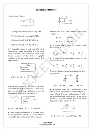
- 1. Sanjeet Singh www.physicsgurukul.com 1. In the network shown: (a) The potential difference across 2D is 5V (b) Current through resistor equals 0.25 A (c) Current through diode 1D is 1.25 A (d) Current through diode 2D is 1.25 A. 2. A sinusoidal voltage of peak value 200 volt is connected to a diode and resistor R in the circuit shown so that half wave rectification occurs. If the forward resistance of the diode is negligible compared to R, the r.m.s voltage across R is approximately (a) 200 (b) 100 (c) 100 2 (d) 283 3. A sinusoidal voltage of r.m.s value of 200 volt is connected to the diode and capacitor C in the circuit shown so that half wave rectification occurs. The final potential difference in volt across C is (a) 500 V (b) 200 V (c) 283 V (d) 141 V 4. Figure shows the connections of two ideal diodes and two capacitors C and 2C. A 120 volt battery is connected to the input terminals with a at positive potential and b at lower potential. The output voltage is a (a) 60 V (b) 40 V (c) 30 V (d) 20 V. 5. The average value of output D.C. current in a full wave rectifier is (a) 0 2 I (b) 0I (c) 0 2 I (d) 02I 6. The average value of output direct current in a half wave rectifier will be (a) 02I (b) 0 2 I (c) 0 2 I (d) 0I 7. In figure the approximate value of potential drop, 0V across R is: (a) 0 (b) -5V (c) 5V (d) 10 V 8. Two junction diodes one of germanium (Ge) and other of silicon are connected as shown in figure to a battery of emf 12 V and a load resistance 10 K . The germanium diode conducts at 0.3 V and silicon diode at 0.7 V. When a current flows in the circuit, the potentials of the terminal Y will be (a) 12 V (b) 11 V (c) 11.3 V (d) 11.7 V Electronic Devices
- 2. Sanjeet Singh www.physicsgurukul.com 9. What is the current in the circuit shown in figure? (a) 0 amp (b) 2 10 amp (c) 1 amp (d) 0.10 amp 10. In the figure potential difference between A and B is (a) 0 (b) 5 volt (c) 10 volt (d) 15 volt