
Recommended
More Related Content
What's hot
What's hot (8)
Similar to Kuhn landsman 6400 manual
Similar to Kuhn landsman 6400 manual (20)
More from PartCatalogs Net
More from PartCatalogs Net (20)
Recently uploaded
Recently uploaded (20)
Kuhn landsman 6400 manual
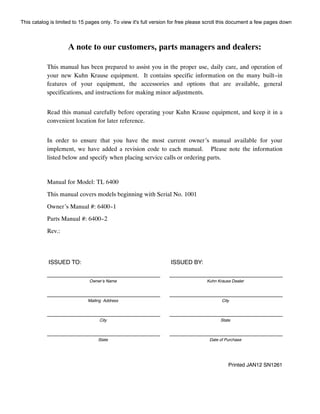
- 1. A note to our customers, parts managers and dealers: This manual has been prepared to assist you in the proper use, daily care, and operation of your new Kuhn Krause equipment. It contains specific information on the many built--in features of your equipment, the accessories and options that are available, general specifications, and instructions for making minor adjustments. Read this manual carefully before operating your Kuhn Krause equipment, and keep it in a convenient location for later reference. In order to ensure that you have the most current owner’s manual available for your implement, we have added a revision code to each manual. Please note the information listed below and specify when placing service calls or ordering parts. Manual for Model: TL 6400 This manual covers models beginning with Serial No. 1001 Owner’s Manual #: 6400--1 Parts Manual #: 6400--2 Rev.: ISSUED TO: ISSUED BY: Owner’s Name Kuhn Krause Dealer Mailing Address City City State State Date of Purchase Printed JAN12 SN1261 This catalog is limited to 15 pages only. To view it's full version for free please scroll this document a few pages down
- 2. PARTCATALOGS.NET This catalog is limited to 15 pages only. To view it's full version on PartCatalogs.net, please scroll it a few pages down or find the link in the description. Dear SlideShare user!
- 3. KUHN KRAUSE WARRANTY STATEMENT (Kuhn Krause Serial Numbered Wholegoods purchased subsequent to May 1, 2008) Note: This warranty is limited to the equipment and parts sold in North America and all warranty work must be accomplished by a Kuhn Krause, Inc. Authorized Service Center rated to perform maintenance on Kuhn Krause Products. A. KUHN KRAUSE, INC. (“KRAUSE”) LIMITED WARRANTY. (1) Subject to the limitations and conditions hereinafter set forth, Kuhn Krause warrants, at the time of delivery by Kuhn Krause to be free from (i) defects in materials or workmanship, and (ii) defects in design that in the view of the state of the art as of the date of manufacture should have been foreseen provided, however, that the defect must be discovered and reported to Kuhn Krause within the periods specified as follows. For a period of one year all new serial numbered production agricultural units covered by this warranty; for a period of thirty--six (36) months the tongue weldment, center frame weldment, wing frame weldments, disc harrow gang bearings and K--Tine field cultivator shanks. (2) Kuhn Krause does not warrant disc blades, shanks, hydraulic cylinders, accessories and other parts not manufactured by it, but supplied with or as a part of its products. Kuhn Krause will, however, obtain and pass on any adjustments provided by the manufacturers of such parts under these manufacturer’s warranties. Tires supplied on Kuhn Krause products, will be warranted by the tire manufacturer’s retail outlets. (3) The entire extent of Kuhn Krause’s liability shall be limited to that of either reimbursing Buyer for its costs of purchasing a rebuilt, over--hauled or repaired part from either Kuhn Krause or a proper Kuhn Krause Authorized Service Center or, at Kuhn Krause’s election, reimbursing buyer for its costs of having the part repaired at a proper Kuhn Krause Authorized Service Center. If Kuhn Krause elects not to repair the part and if neither a rebuilt, over--hauled or repaired part is, in Kuhn Krause’s opinion, timely available then Kuhn Krause will reimburse buyer for its costs of purchasing a new part from either Kuhn Krause or a proper Kuhn Krause Authorized Service Center. The labor necessary to remove from the product such part or parts and to install in the product such part or parts, as well as any repair made as the result of improper installations by Kuhn Krause, shall be covered by this warranty, provided the work is performed at a proper Kuhn Krause Authorized Service Center.K If return of the defective part is required, it must be returned shipping prepaid to Kuhn Krause, Inc. Kuhn Krause’s limited warranty will apply to any part repaired or replaced by a proper Kuhn Krause Authorized Service Center pursuant to Kuhn Krause’s Limited Warranty: however, the applicable warranty for such part repaired or replaced shall be limited to the unexpired portion of Kuhn Krause’s Limited Warranty described in paragraph (1) or (2) above, as applicable. In other words, the warranty period of the part repaired or replaced does not start over from the date of reinstallation. K[Kuhn Krause, Inc. will repair or replace, free of charge, any part of the product found to be defective, within the specified warranty periods, after an inspection of the part has deemed it to be defective. Inspection must be performed by an authorized agent of Kuhn Krause, Inc. or returned to the Kuhn Krause factory for inspection and disposition. Warranty labor will be considered during the first year of warranty only. Kuhn Krause, Inc. will establish and publish an hourly flat rate for shop labor and reimbursement during the first year of the warranty period. Kuhn Krause does not allow credit for the cost of travel time, mileage or hauling as a warranty allowance. During the remaining second and third year, when applicable, Kuhn Krause will repair or replace the defective part, without consideration of labor charges.] (4) Routine services (such as inspections, field settings, adjustments, etc.) and replacement of items which deteriorate from expected normal wear and tear or exposure (such as paint, tires, hoses, blades, sweeps, points, shank wear strips, etc.) are not covered by this Limited Warranty. Such routine services and replacements required during the course of operation are not considered to be the result of any defect in the product. This catalog is limited to 15 pages only. To view it's full version for free please scroll this document a few pages down
- 4. B. LIMITATIONS APPLICABLE TO KUHN KRAUSE’S LIMITED WARRANTY. (1) Kuhn Krause, Inc. will be relieved of all obligations and liability under this warranty if: (i) The alleged defect in the part is due to misuse or neglect on the part of someone other than Kuhn Krause; or (ii) Kuhn Krause’s identification mark or name or serial number has been removed from the part in question; or (iii) The product and/or equipment have not been maintained, operated or stored either in accordance with applicable manuals, communications or other written instructions of Kuhn Krause or any manufacturer of the part involved, or in accordance with applicable regulations and advisory circulars unless buyer shows that such maintenance, operation or storage was not a contributory cause of the defect; or (iv) The part in question has been modified or altered after delivery other than by the manufacturer or in accordance with a modification or alternation scheme approved in writing by the manufacturer; or (v) The product is used for purposes other than conventional owner/operator usage. Usage not considered conventional owner/operator includes, but is not limited to, operation conditions that consist of rocks or other obstructions. (2) For the purpose of this Warranty, no part of the product or equipment will be regarded as breaching the limited warranty merely because, subsequent to its delivery, some modification or alteration becomes necessary for product improvements or in order to meet a change in the requirements of any applicable regulation. (3) TO THE EXTENT ALLOWED BY APPLICABLE LAW, BUYER WAIVES AS TO KUHN KRAUSE ALL OTHER WARRANTIES, WHETHER OF MERCHANTABILITY, FITNESS OR OTHERWISE, THERE ARE NO WARRANTIES WHICH EXTEND BEYOND THE DESCRIPTION ON THE FACT HEREOF. (4) TO THE EXTENT ALLOWED BY APPLICABLE LAW, THE OBLIGATIONS OF KUHN KRAUSE SET FORTH HEREIN SHALL BE THE EXCLUSIVE REMEDIES FOR ANY BREACH OF WARRANTY HEREUNDER, AND, TO THE SAME EXTENT, KUHN KRAUSE SHALL NOT BE LIABLE FOR ANY GENERAL, CONSEQUENTIAL OR INCIDENTAL DAMAGES, INCLUDING, WITHOUT LIMITATION, ANY DAMAGES FOR DIMINUTION OF MARKET VALUE, LOSS OF USE OR LOSS OF PROFITS, OR ANY DAMAGES TO THE PRODUCT CLAIMED BY BUYER OR ANY OTHER PERSON OR ENTITY UPON THE THEORIES OF NEGLIGENCE OR STRICT LIABILITY IN TORT. (5) ANY ACTION BY BUYER FOR BREACH OF THIS WARRANTY BY EITHER KUHN KRAUSE OR SELLER MUST BE COMMENCED WITHIN (1) YEAR AFTER THE CAUSE OF ACTION ACCRUES. This catalog is limited to 15 pages only. To view it's full version for free on PartCatalogs.net, please click here or find the link in the description
- 5. EstaЫishing Customer Warranty Dealer's OЬligation 1. It is the responsiЬility of the dealer to complete а Delivery Report and Warranty Registration form. The form should contain the model, serial number, delivery date, along with the complete dealer and customer address. This form must Ье signed Ьу the dealer and customer upon physical delivery of the product to the customer. The dealer must complete the pre-delivery check list provided on the Delivery Report and Warranty Registration form. 2. Dealer will review the Predelivery Check List located in the front of the operation manual with the customer and / or operator. This should Ье signed Ьу the dealer at time of delivery to the retail customer. 3. The dealer will review the Customer Review Sheet located at the front of the operation manual with the customer and / or operator. This should Ье signed Ьу the dealer representative and the customer. 4. An authorized Kuhn Krause, lnc. dealer will submit warranty claims on behalf of the customer. All claims must Ье handled through the dealer. They will then Ье given to the Kuhn Krause District Manager for inspection and approval. Warranty requests must Ье filed within 60 days from completion of the repair for consideration. 5. It is the dealer's responsiЬility to service the warranty on products sold through said dealership. This warranty gives you specific rights, and you тау also have other rights which vary from state to state. This catalog is limited to 15 pages only. To view it's full version for free on PartCatalogs.net, please click here or find the link in the description
- 6. Establishing Customer Warranty Customer’s Obligation 1. The customer is responsible for reading the operation manual supplied with each serial numbered unit. The manual describes the safe and correct operating procedures of the specific product. The operation manual will also instruct the user on recommended lubrication and maintenance of the product. 2. The customer will advise the dealer of the anticipated start date of the product so a dealer representative can be on hand to make necessary field adjustments. 3. The owner is also responsible for inspecting the product during and after use. If a part has failed or is in need of repair, it should be replaced. When continued use of the product would result in excessive wear of other components, the part should be replaced before operation is continued. Continued use of the product may void warranty on other parts damaged from this condition. The user must make the machine available to the dealer for a warranty repair. 4. It is the customer’s responsibility to deliver his machine to an authorized Kuhn Krause dealer for completion of a warranty repair. If the dealer agrees to make a service trip to the customer’s residence, it is an agreement between the dealer and the customer. Kuhn Krause will not allow warranty credit for the cost of travel, mileage, or hauling. 5. Warranty labor consideration will only be given during the first year of warranty. Any labor charge for the 2nd or 3rd year on the limited warranty will be at the customer’s expense. This warranty gives you specific rights, and you may also have other rights which vary from state to state. This catalog is limited to 15 pages only. To view it's full version for free on PartCatalogs.net, please click here or find the link in the description
- 7. 1 TL 6400 SERIES LANDSTAR DEALER PREDELIVERY CHECK SHEET TO BE CHECKED BY DEALER CUSTOMER DATE ADDRESS COUNTY DEALER ADDRESS COUNTY MODEL NUMBER SERIAL NUMBER DEALER CHECK: 1. Check to see that all rocker shaft bolts are tight and pins are in place. 2. Check to see that hydraulic cylinders are full of oil (air bled out of cylinders). Clevis pins with hairpin clips should be in place. Models TL 6400--9, TL 6400--12, TL 6400--15 require 6 Quarts / 5.76 Liters of oil; Models TL 6400--18 and TL 6400--21 require 20 Quarts / 19 Liters of oil; Models TL 6400--24 and TL 6400--27 require 24 Quarts / 22.7 Liters of oil; Model TL 6400--31 will require 34 Quarts / 32.2 Liters of oil, and Model TL 6400--36 will require 51 Quarts / 48 Liters of oil. 3. Examine hydraulic hoses to see that they are protected from damage. 4. Bolts attaching the walking tandem to the wheel arms should be tight. Check to see that bearings have been adjusted and greased. 5. Check lug bolt holding wheels to the hub to see that they are properly torqued. 1/2” Wheel Nuts to 90 Ft. Lbs., 9/16” Wheel Nuts to 120 Ft. Lbs., and 5/8” Wheel Nuts to 170 Ft. Lbs. 6. See chart below for correct size tires and their locations. Inflate all tires to the following pressures: MODEL CENTER SECTION WING SECTION TL 6400--09 (4) 9.5L x 15, 8--Ply inflated to 44 PSI -- -- N/A -- -- TL 6400--12 (4) 9.5L x 15, 8--Ply inflated to 44 PSI -- -- N/A -- -- TL 6400--15 (4) 9.5L x 15, 8--Ply inflated to 44 PSI -- -- N/A -- -- TL 6400--18 (4) 11L x 15, 12--Ply inflated to 52 PSI (4) 9.5L x 15, 8--Ply inflated to 44 PSI TL 6400--21 (4) 11L x 15, 12--Ply inflated to 52 PSI (4) 9.5L x 15, 8--Ply inflated to 44 PSI TL 6400--24 (4) 11L x 15 FI inflated to 90 PSI (4) 11L x 15, 8--Ply inflated to 36 PSI TL 6400--27 (4) 12.5FI, 8--Bolt inflated to 90 PSI (4) 11L x 15, 8--Ply inflated to 36 PSI TL 6400--31 (4) 12.5FI, 8--Bolt inflated to 90 PSI (4) 11L x 15, 8--Ply inflated to 36 PSI TL 6400--36 (4) 12.5FI, 8--Bolt inflated to 90 PSI (8) 11L x 15, 8--Ply inflated to 36 PSI 7. Check to see that bolts and pins attaching hitch frame and clevis weldment to hitch are in place and tightened. 8. Jack should be operational for support of tongue when implement is not attached to a tractor. 9. Road lock and wing lock are correctly installed and operate satisfactorily. 10. Restrictors are installed in wing lift cylinder rod end ports. 11. All decals are in place per pages P70--P71 of this owner’s manual. 12. Customer review sheet is filled out and signed. 13. A safety chain is provided with a strength rating equal to or greater than the gross weight of the TL 6400 with attachments. 14. Review lighting requirements. Light kits are standard. 15. Check to see that the Owner’s Manual is in the storage tube on the implement. 16. Check to see that the SMV Sign is clean and in place. DELIVERED BY: DATE: This catalog is limited to 15 pages only. To view it's full version for free on PartCatalogs.net, please click here or find the link in the description
- 8. TL 6400 SERIES LANDSTAR CUSTOMER REVIEW SHEET CUSTOMER DATE------------------- ---------- ADDRESS COUNTY------------------- 0EALER--------------------------------- ADDRESS COUNTY------------------- --------- MODEL NUMBER 8ERIAL NUMBER------------ ----------- 1.__0wner's manual provided. 2.__Warranty card filled out and mailed. 3.__Review safety warnings and cautions as listed in this owner's manual. 4.__Review recommended maximum road speed, width, and height for implement. 5.__Review field operational speeds, horsepower, depth, and rock conditions. 6.__Demonstrate the proper use of road lock. 7.__Explain hydraulic cylinder stroke control for depth control of tillage tool. 8.__Review limitations of additional weight and transport speed when adding attachments. 9.__Explain the importance of maintaining the tools through lubrication, checking that bolts are kept tight, and replacement of worn or broken parts. 1O._Recommend that а safety chain Ье used with the tool. 11._Check wheel lug bolts frequently until they become set. 12._Explain lighting requirements for your area. DEALER: DATE----------------- ---------- CUSTOMER: 0АТЕ----------------- ---------- 2 This catalog is limited to 15 pages only. To view it's full version for free on PartCatalogs.net, please click here or find the link in the description
- 9. 3 Contents Rev.10/11 WARRANTY DEALER PREDELIVERY CHECK SHEET 1 CUSTOMER REVIEW SHEET 2 TABLE OF CONTENTS 3 SPECIFICATIONS 4 GENERAL INFORMATION DRAWING 5 OPERATING SECTION PROTECT YOURSELF FROM CHEMICALS O2 SAFETY DECALS / INFORMATIVE DECALS O3--O4 ABOUT YOUR LANDSMAN O5 PREPARING FOR OPERATION O5 PREPARING THE TRACTOR O6 HYDRAULIC SAFETY O6 Disc Gangs O7 HITCHING TO THE TRACTOR O7 UNHITCHING LANDSTAR FROM TRACTOR O8 Transporting O9 Transport Lock Valves O9 Raising and Lowering the Wings O9 Transport Safety O10 Hitch Pin O10 FIELD ADJUSTMENTS O11 Tongue Height Adjustment O11 Depth of Disc Blades O12 Scrapers O13 Sweeps O13 Working Depth O13 Hydraulic Depth Control O13 Flexibility O13 Turning in the Field O13 Hydraulic Disc Gangs O14 STORAGE SUGGESTIONS O14 GENERAL INFORMATION O14 SERVICING O14 General Maintenance O14 Lubrication O15 Wheel Bearings O15 Walking Beams O15 Disc Gangs O15 Repair Parts O16 PROCEDURE TO LOCATE INTERNAL LEAKS O17 Test Cases 1 through 5 O17--O19 TROUBLESHOOTING SECTION O20--O21 HYD. GANG TROUBLESHOOTING SECTION O22 MODEL 6336 WING FOLD SEQUENCE VALVE O23 PARTS SECTION SMV & LIGHT KIT BRACKET ASSEMBLY P1 MAIN FRAME (Models TL6400 9, 12, 15) P2 MAIN FRAME (Models TL6400, 18, 21, 24) P3 MAIN FRAME (Models TL6400 27,31,36) P4--P5 CENTER ROCKER (Models TL6400 9,12,15) P6--P7 CENTER ROCKER (Models TL6400 18,21,24) P8--P9 CENTER ROCKER (Models TL6400 27 thru 36) P10--P11 RIGID TONGUE (Models TL6400 9 thru 24) P12--P13 RIGID TONGUE (Models TL6400 27 thru 36) P14--P15 CUSHION TONGUE (Models TL6400 9 thru 36) P16--P17 WING FRAMES (MODEL TL6400 18 thru 31) P18--P19 WING ROCKER (MODEL TL6400 18 thru 31) P20--P21 WING FRAMES & ROCKERS (TL6400--36) P22--P23 WALKING BEAM ASSEMBLIES P24--P25 GAUGE WHEEL ASSEMBLY P26--P27 WHEELS & TIRES P28 TIE ROD INFORMATION CHART P29 DISC GANG & BEARING ARM ASSEMBLY P30--P31 XT270 SHANK ASSEMBLY P32 SPRING SHANK ASSEMBLY P33 LEFT & RIGHT STAR WHEEL ASSEMBLIES P34--P35 WING LIFT GROUP (TL6400 -- 18 thru 31) P36--P37 INSIDE/OUTSIDE WING LIFT (TL6400--36) P38--P39 DEPTH VALVE ASSEMBLY P40 HYD. HOSE STAND & LOCK VALVE BRACKET P41 HYDRAULICS (MODELS TL6400 9,12,15) P42--P43 HYDRAULICS (MODEL TL6400 18,21) P44--P45 HYDRAULICS (MODELS TL6400 24) P46--P47 HYDRAULICS (MODEL TL6400 27,31) P48--P49 HYDRAULICS (MODEL TL6400 36) P50--P51 HYDRAULIC HOSE W/PLASTIC GRIP ASS’M. P52 PRINCE CYLINDER 4--1/4” X 10” P53 PRINCE CYLINDER 4” X 10” P54 PRINCE CYLINDER 3--3/4” X 10” P55 PRINCE CYLINDER 4” X 24” P56 PRINCE CYLINDER 4” X 30” P57 PRINCE CYLINDER 4” X 32” P58 PRINCE CYLINDER 5” x 32” P59 PRINCE CYLINDER 2” X 5--7/8” P60 CYLINDER SUPPORT ASSEMBLY P61 DISC GANG HYDRAULIC HOSE & FITTINGS P62 PACKER HITCH ASSEMBLY P63 HYDRAULIC DISC GANG PLACEMENTS P64--P69 DECALS & REFLECTORS P70--P71 LIGHT KIT P72 REAR RECEPTACLE PARTS P73--P74 ASSEMBLY SECTION GENERAL ASSEMBLY INSTRUCTIONS A1 CENTER FRAME ASSEMBLY A2 TONGUE ASSEMBLY A4 WALKING BEAM ASSEMBLY A5 SELF SUPPORTING CENTER SECTION A5 WING FRAMES & ROCKERS A5--A7 WING FOLD ASSEMBLY A7 GANG BEAMS -- SCRAPER BAR A8 UNASSEMBLED GANGS/REPAIR SEQUENCE A9--A10 DISC SCRAPER A11 SHANK EXTENSION ASSEMBLY A11 SPRING SHANKS & STAR WHEELS A11 HYDRAULICS ASSEMBLY A12--A14 DISC GANG HYDRAULICS ASSEMBLY A14 DECALS & LIGHT KIT A15 LIGHT KIT ILLUSTRATION & FINAL CHECK A16 PLACEMENT DRAWINGS FOR MODELS: TL6400--9 A18--A19 TL 6400--24 A28--A29 TL 6400--12 A20--A21 TL 6400--27 A30--A31 TL 6400--15 A22--A23 TL 6400--31 A32--A33 TL 6400--18 A24--A25 TL 6400--36 A34--A35 TL 6400--21 A26--A27 PARTS INDEX Index 1--5 This catalog is limited to 15 pages only. To view it's full version for free on PartCatalogs.net, please click here or find the link in the description
- 10. TL 6400 LANDSTAR SPECIFICATIONS 9/02 NUMBER OF NUMBER OF CUT CUT DISC SHANKS SHANKS WIDTH WIDTH NUMBER DISC BLADE WITH 7" WITH9" MODEL FEET METRES DISC SPACING SIZE SPACING SPACING TL 6400-9 9' О" 2.74 12 9-1/8" 20" 17 13 TL 6400-12 12' О" 3.66 16 9-1/8" 20" 21 17 TL 6400-15 15' О" 4.57 20 9-1/8" 20" 27 21 TL 6400-18 18' О" 5.49 24 9-1/8" 20" 31 25 TL 6400-21 21' О" 6.40 26 9-1/8" 20" 37 29 TL 6400-24 24' О" 7.32 32 9-1/8" 20" 41 33 TL 6400-27 27' О" 8.23 36 9-1/8" 20" 45 37 TL 6400-31 31' 6" 9.60 40 9-1/8" 20" 53 43 TL 6400-36 36' О" 10.97 46 9-1/8" 20" 61 49 TL 6400 LANDSTAR TRANSPORT WIDTH & HEIGHT MODEL DIMENSION '/ DIMENSION 'В' TL 6400-9 TL 6400-12 TL 6400-15 TL 6400-18 TL 6400-21 TL 6400-24 TL 6400-27 TL 6400-31 TL 6400-36 - - - - - - - - - - - - 9' 6" 11' О" 12' 6" 12' 6" 14' 6" 11' 6" ------- в ---------- 1О' О" 12' 6" 16' 3" 12' О" 12' О" 12' О" 14' 11" 14' 11" 14' 11" * WIDTH & HEIGHT МАУ VARY WITH FINISHING ATTACHMENT12194 4 This catalog is limited to 15 pages only. To view it's full version for free on PartCatalogs.net, please click here or find the link in the description
- 11. IMPORTANT ....,_ GREASE ЕАСН 24 HOURS OF USEREAD ALL SAFETY DECALS ON THI5 UNIT AND SAFETY INFORMATION IN THI5 OWNER'S MANUAL ® СНЕСК THESE POINTS PERIODICALLY FOR WEAR СНЕСК POINTS OR SWEEPS FOR WEAR, TURN OR REPLACE WHEN NEEDED. TORQUE Т/Е ROD ТО 1000 FT.LB. А ROAD IMPLEMENT АТ " А REASONABLE SPEED DO NOT EXCEED 25 М.Р.Н. @нINGE PINS & BOLTS СВ PLACESJ ® Н/ТСН & CLEV/5 BOLTS LEVEL UNIТ W/ТН JACK ALWAYS PIN TRACTOR DRA�BAR BEFORE TRANSPORTING USE А SAFETY CHAIN WITH ТНЕ TENSILE STRENGTH EQUAL ТО ТНЕ GROSS �EIGHT OF ТНЕ LOAD BEING TOWED. А lNARNING! СНЕСК Т/RE PRESSURE BEFORE OPERAТ/ON 9.5Lх 15 8-Ply to 44 PSI 11Lx 15 12-Ply to 52 PSI 11Lx 15 FI to 90 PSI 12.5FI 8-Bolt to 90 PSI ТORQUE 1/2'WHEEL NUTS ТО 90 FT. LBS. ТORQUE 9/1б'WHEEL NUTS ТО 120 FT. LBS. ТORQUE 5/8'WHEEL NUTS ТО 170 FT. LBS. СНЕСК FREQUENTLY UNТIL SEATED. ESCAPING FLUID UNDER PRESSURE CAN PENETRATE ТНЕ SKIN CAUSING SERIOUS INJURY. AVOID ТНЕ HAZARD ВУ RELIEVING PRESSURE BEFORE DISCONNECTING HYDRAULIC LINES. TIGHTEN ALL CONNECTIONS BEFORE APPLYING PRESSURE. SEARCH FOR LEAKS WITH А PIECE OF CARDBOARD. PROTECT HANDS & BODY FROM HIGH PRESSURE FLUIDS. IF AN ACCIDENT OCCURS, SEE А DOCTOR IMMEDIATELY. ANY FLUID INJECTED INTO SKIN MUST ВЕ SURGICALLY REMOVED WIТHIN А FEW HOURS, OR GANGRENE МАУ RESULT. Rev. 1/09 М6400-13 5 This catalog is limited to 15 pages only. To view it's full version for free on PartCatalogs.net, please click here or find the link in the description
- 12. .·.·.· ....,.. =::�� ..·.,,;,;��,;�/?.:::· .,·.... ...'::.::....· 6 ·.·.·:':·:.:.=-·:·::;{1 ....,,;,>,;:���-;:;{ This catalog is limited to 15 pages only. To view it's full version for free on PartCatalogs.net, please click here or find the link in the description
- 13. OPERATING SECTION This catalog is limited to 15 pages only. To view it's full version for free on PartCatalogs.net, please click here or find the link in the description
- 14. SAFETY ALERT SYMBOL '• ВЕ ALERT ТО ТНЕ POSSIBILIТY OF PERSONAL INJURY. THIS SYMBOL IDENTIFIES IMPORTANT SAFEТY MESSAGES. CAREFULLY READ ТНЕ MESSAGE ТНАТ FOLLOWS. TEN MOST COMMON HAND SIGNALS USED IN ТНЕ FIELD START ТНЕ ENGINE THIS FAR TO GO MOVE OUT OR ТАКЕ OFF MOVE TOWARD МЕ STOP RAISE ТНЕ EQUIPMENT SPEED 1Т UP �� LOWER ТНЕ EQUIPMENT SLOW IT DOWN STOP ТНЕ ENGINE This catalog is limited to 15 pages only. To view it's full version for free on PartCatalogs.net, please click here or find the link in the description
- 15. :Notes This catalog is limited to 15 pages only. To view it's full version for free on PartCatalogs.net, please click here or find the link in the description
- 16. PARTCATALOGS.NET End of 15-page catalog excerpt Thanks for viewing this catalogs’ first 15 pages on Slideshare! To view the full version of this catalog for free on PartCatalogs.net, please visit this link