Instructions AIMPOINT LPI | Optics Trade
•
0 likes•259 views

Instructions AIMPOINT LPI | Optics Trade
![2.2.3. Adjustment of the Laser beam:
The laser can be adjusted horizontally and vertically.
Horizontal adjustment using the side located adjustment screws (3).
Vertical adjustment using the adjustment screws located on top (2).
To correct the point of impact, proceed as follows:
• Turning the side adjustment screw in the “+” direction moves the point of
impact to the right.
• Turning the side adjustment screw in the “-” direction moves the point of
impact to the left.
• Turning the top adjustment screw in the “+” direction moves the point of
impact down.
• Turning the top adjustment screw in the “-” direction moves the point of
impact up.
One click equals approx. 3 cm at 100 m
MAINTENANCE
The LPI requires no routine maintenance. When the lenses are soiled by dirt
or gun powder residue, a soft optical cloth is required to wipe the lens clean
If required, the reflection shields can be removed (7).
Safety notice:
LASER beams can cause damage to the human eye. Target lasers are for
use by trained personnel only. The user is responsible to maintain the safety
precautions defined by local laws.
The use of this equipment is the sole responsibility of the operator.
User’s Manual for
AIMPOINT LPI
IR aiming laser device
Aimpoint AB
Jägershillgatan 15
SE- 213 75 Malmö, Sweden
Phone +46 (0)40 671 50 20
Fax +46 (0)40 21 92 38
e-mail: info@aimpoint.se
www.aimpoint.com
Aimpoint Inc.
14103 Mariah Court
Chantilly, VA 20151-2113, USA
Phone +1 703-263-9795
Fax +1 703-263-9463
e-mail: info@aimpoint.com
www.aimpoint.com
© 2008 - Contents property of Aimpoint - All rights reserved. [11536-1]
2.1.2. Installing remote switch pad trigger
Screw Trigger in to the side connector of the laser unit (5).
Attach Trigger pad to weapon using the Velcro lock. Usual positions are on
the pistol handle or over the thermal cover of the barrel using the supporting
hand for activation.
2.1.3 Installing the battery
Open battery cover (6). Insert battery in the correct direction in the same way
as you fit the battery in the red dot sight. Make sure that the battery contacts
are clean. Close battery cover.
2.2 OPERATING PROCEDURES
2.2.1. Selecting a laser:
Turn the selector (4) to the desired position. The laser beam will only be
activated once you press the switch pad.
Left Position: Laser OFF
Position 1: The Laser is at low power.
Position 2: The Laser is at high power.
2.2.2. Switch pad trigger activation:
The laser must be on position 1 or 2.
Pressing the Trigger switch activates the Laser.
When the switch is released, the laser is interrupted.](data:image/gif;base64,R0lGODlhAQABAIAAAAAAAP///yH5BAEAAAAALAAAAAABAAEAAAIBRAA7)
Recommended
More Related Content
What's hot
What's hot (17)
Similar to Instructions AIMPOINT LPI | Optics Trade
Similar to Instructions AIMPOINT LPI | Optics Trade (20)
More from Optics-Trade
More from Optics-Trade (20)
Recently uploaded
Recently uploaded (20)
Instructions AIMPOINT LPI | Optics Trade
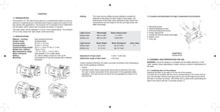
- 1. 1.3 Location and description of major components and functions. 1. Mounting screws 2. Vertical adjustment screw 3. Horizontal adjustment screw 4. Power selector/Off 5. Contact for Remote switch pad trigger 6. Battery cover 7. Lens cap CHAPTER II OPERATION 2.1 Assembly and preparation for use wARNING: Insure the weapon is unloaded and the safety selector is in the ”safe” position before attempting to install, remove or perform maintenance on the laser. 2.1.1 Installing laser on the weapon Installing the laser on the sight or on the rail of the weapon The laser has to be fitted with the mount corresponding to the mount used on your red dot sight. Remove the upper part of your red dot sight mount and fit the laser in its place as shown. Use thread lock (Loctite) when assembling the laser to the mount with the 2 mounting screws (1). CHAPTER I 1.1 Presentation The Aimpoint LPI, IR Laser Aiming Device is a development based on long ex- perience in engineering and manufacturing of lasers ranging from pistol to mili- tary infantry rifle applications. The Aimpoint LPI is intended to fit on AIMPOINT red dot sights, which means that no special rail system is required. The laser beam can be adjusted in X and Y axis independently. The Aimpoint LPI is a truly unique tool, light weight, small and sturdy. 1.2 Specification Material - housing: High strength Aluminum Surface finish: Anodized black Housing width: 44 mm +/- 0,5 mm Housing height: 24 mm +/- 0,5 mm Overall (housing) length: (47,5 +/- 2 mm) 77 mm +/- 2 mm Weight (incl. battery): 150 gr, 5,3 oz Max temperature range: - 10º to + 50º C , +14º to 122º F Water resistance: Submersible to 10 m water depth Battery: 3V, Lithium battery of type DL1/3N, 2L76 Mounting: The Aimpoint LPI can be mounted with 4 different interfaces. Setting: The Laser has two different power settings to enable the selection of the power for short range or long range. The performance of the night vision equipment used varies from manufacturer and the range for the low and high power will differ accordingly. Light source Wavelength Beam output power Setting High 840 nm (IR)* 0.1 mW** Setting Low 840 nm (IR)* 0.005 mW** Light source Beam Shape Beam divergence Laser class Setting High 5 x 2 mm typ 0.5 mrad 1** Setting Low 5 x 2 mm typ 0.5 mrad Adjustment of laser beam 1 Click = 0.28 mrad Adjustment range of laser beam ± 20 mrad Unless indicated otherwise, the data is accurate at ambient room temperature and normal operating conditions. * Typical. ** Important notice: Beam output power will be set as required by the user. The user is solely responsible for the observation of the applicable safety regulations. The max and the min level can be separated by a factor of no more than 20.
- 2. 2.2.3. Adjustment of the Laser beam: The laser can be adjusted horizontally and vertically. Horizontal adjustment using the side located adjustment screws (3). Vertical adjustment using the adjustment screws located on top (2). To correct the point of impact, proceed as follows: • Turning the side adjustment screw in the “+” direction moves the point of impact to the right. • Turning the side adjustment screw in the “-” direction moves the point of impact to the left. • Turning the top adjustment screw in the “+” direction moves the point of impact down. • Turning the top adjustment screw in the “-” direction moves the point of impact up. One click equals approx. 3 cm at 100 m MAINTENANCE The LPI requires no routine maintenance. When the lenses are soiled by dirt or gun powder residue, a soft optical cloth is required to wipe the lens clean If required, the reflection shields can be removed (7). Safety notice: LASER beams can cause damage to the human eye. Target lasers are for use by trained personnel only. The user is responsible to maintain the safety precautions defined by local laws. The use of this equipment is the sole responsibility of the operator. User’s Manual for AIMPOINT LPI IR aiming laser device Aimpoint AB Jägershillgatan 15 SE- 213 75 Malmö, Sweden Phone +46 (0)40 671 50 20 Fax +46 (0)40 21 92 38 e-mail: info@aimpoint.se www.aimpoint.com Aimpoint Inc. 14103 Mariah Court Chantilly, VA 20151-2113, USA Phone +1 703-263-9795 Fax +1 703-263-9463 e-mail: info@aimpoint.com www.aimpoint.com © 2008 - Contents property of Aimpoint - All rights reserved. [11536-1] 2.1.2. Installing remote switch pad trigger Screw Trigger in to the side connector of the laser unit (5). Attach Trigger pad to weapon using the Velcro lock. Usual positions are on the pistol handle or over the thermal cover of the barrel using the supporting hand for activation. 2.1.3 Installing the battery Open battery cover (6). Insert battery in the correct direction in the same way as you fit the battery in the red dot sight. Make sure that the battery contacts are clean. Close battery cover. 2.2 OPERATING PROCEDURES 2.2.1. Selecting a laser: Turn the selector (4) to the desired position. The laser beam will only be activated once you press the switch pad. Left Position: Laser OFF Position 1: The Laser is at low power. Position 2: The Laser is at high power. 2.2.2. Switch pad trigger activation: The laser must be on position 1 or 2. Pressing the Trigger switch activates the Laser. When the switch is released, the laser is interrupted.