1. Implementation of a Vision System for the Identification of
Casting Defects in Turbocharger Components
By: Oliver Fletcher,
Supervisor: N. Cullinan, Technical Supervisor: N. Murphy,
Overview
This research presents a prototype
vision system capable of detecting casting
defects in turbocharger components. A
method has been established of detecting
two of the most common defects that result
from casting of compressor wheels.
These defects are: 1) “through holes” (Figure 1)
and 2) “bent blades” (Figure 2).
Experimental
Experimental work has been broken into two
sections. 1) “through holes” & 2) “bent blades”
1)“through hole”
Flaw Detection, works by Calculating the gray
average value within the segmented area. If the
PV310 detects an area more than a certain level
of difference in average gray, the device judges it
as a flaw.
Flaw detection requires a “threshold” limit to be
set and an inspection area to be determined (Figure
4). If required pre-processes can be used.
Trials were undertaken to determine the correct
positioning of the lighting source, to acquire
“directional front illumination”. Front lighting
(Figure 6) and Rear lighting (Figure 7).
Four Selected Pre-processes: Erosion (Figure 8), Grey
Cut (Figure 9), Prewitt (Figure 10) & Dilation (Figure 11).
Figure 3. Prototype vision system
Figure 1. Red box indicates “through hole”
Figure 12. Blade with ambient
light.
Results
The results have been broken in too two
sections: 1) “through holes” & “bent blades”.
1) “through holes”
Thirty six individually positioned “through
holes” were inspected using front lighting.
Any holes that failed were re-tested using
rear lighting.
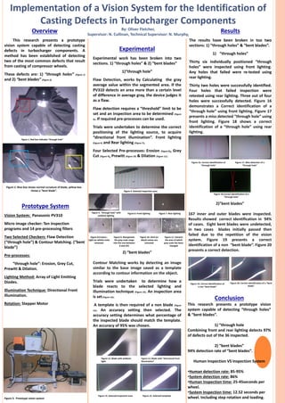
Thirty two holes were successfully identified.
Four holes that failed inspection were
retested using rear lighting. Three out of four
holes were successfully detected. Figure 16
demonstrates a Correct identification of a
“through hole” using front lighting. Figure 17
presents a miss detected “through hole” using
front lighting. Figure 18 shows a correct
identification of a “through hole” using rear
lighting.
Figure 4. Selected inspection area.
Conclusion
This research presents a prototype vision
system capable of detecting “through holes”
& “bent blades”.
1) “through hole
Combining front and rear lighting detects 97%
of defects out of the 36 inspected.
2) “bent blades”
94% detection rate of “bent blades”.
Human Inspection VS Inspection System
•Human detection rate: 85-95%
•System detection rate: 86%
•Human Inspection time: 25-45seconds per
wheel.
•System Inspection time: 12.52 seconds per
wheel. Including step rotation and loading.
Prototype System
Vision System: Panasonic PV310
Micro image checker: Ten inspection
programs and 14 pre-processing filters
Two Selected Checkers: Flaw Detection
(“through hole”) & Contour Matching. (“bent
blade”)
Pre-processes:
“through hole”: Erosion, Grey Cut,
Prewitt & Dilation.
Lighting Method: Array of Light Emitting
Diodes.
Illumination Technique: Directional Front
Illumination.
Rotation: Stepper Motor
Figure 2. Blue box shows normal curvature of blade, yellow box
shows a “bent blade”.
Figure 11. Extracts
the area of which
gray scale has been
changed
Figure 5. “through hole” with
ambient lighting.
Figure 6: Front lighting Figure 7. Rear lighting
Figure 8.Erosion :
Light (or white) noise
removed.
Figure 9. Reorganizes
the gray scale range
into the one between
0 and 255
Figure 10. Dark (or
black) noises are
removed.
2)”bent blades”
167 inner and outer blades were inspected.
Results showed correct identification in 94%
of cases. Eight bent blades were undetected,
in two cases blades initially passed then
failed due to the repetition of the vision
system. Figure 19 presents a correct
identification of a non “bent blade”. Figure 20
presents a correct detection.
2) “bent blades”
Contour Matching works by detecting an image
similar to the base image saved as a template
according to contour information on the object.
Trials were undertaken to determine how a
blade reacts to the selected lighting and
illumination technique (Figure 13). An inspection area
is set(Figure 14).
A template is then required of a non blade (Figure
15). An accuracy setting then selected. The
accuracy setting determines what percentage of
the inspected blade should match the template.
An accuracy of 95% was chosen.
Figure 13. Blade with “directional front
illumination”
Figure 15. Selected templateFigure 14. Selected inspection area
Figure 16. Correct identification of
“through hole”
Figure 17. Miss detection of a
“through hole”
Figure 18.Correct identification of a
“through hole”
Figure 19. Correct identification of
a non “bent blade”
Figure 20. Correct identification of a “bent
blade”