SlideShare a Scribd company logo
1 of 29
Download to read offline
Manual Transmissions & Transaxles – Course 302
1. Identify and describe manual transmission design features and operation.
2. Describe transmission powerflow.
3. Describe manual transmission construction.
4. Identify and describe the operation of the following transmission
components:
a. Synchronizers
b. Shift mechanisms
c. Key inertia lock mechanism
5. Identify and describe gear shift control.
6. Describe transmission lubrication.
Section 3
Manual Transmissions
Learning Objectives:
Component Testing
2 TOYOTA Technical Training
The manual transmission transfers power from the engine to the propeller
shaft. It converts and multiplies rotational speed, allowing engine RPM to
remain in it’s limited optimal power range while providing a wide range of
RPM to the propeller shaft; which, in turn, controls vehicle speed.
Multiple gear sets within the transmission provide gear ratios to best
utilize the engine’s torque. A gear ratio of about 4:1 in first gear
provides high torque to begin moving the vehicle. In contrast, a higher
gear ratio of about 1:1 reduces engine speed at higher vehicle speeds
when less torque is required to maintain momentum.
Understanding manual transmission design features increases your
knowledge of transmission operation, and provides for easier and more
accurate problem diagnosis.
The rear wheel drive transmission is constructed with three shafts, five
forward gears, and a reverse gear.
Transmission
Components
The rear wheel
drive transmission is
constructed with three
shafts, five forward gears,
and a reverse gear.
The input shaftÄŠalso known as a main drive gear or clutch shaftÄŠis
driven by the clutch disc and drives the counter gear shaft. The input
shaft is supported by the pilot bearing at the end of the crankshaft and
a bearing at the front of the transmission case.
Section 3
Manual Transmissions
Introduction
Components
Input Shaft
TRX – ESP Troubleshooting Guide
Manual Transmissions & Transaxles – Course 302
The counter gear shaftÄŠalso known as a cluster gearÄŠdrives the
gears (1st, 2nd, 3rd, and 5th) on the output shaft. This shaft is
supported by bearings in the intermediate plate, at the front of the
transmission case, and in the extension housing.
The output shaftÄŠalso known as the mainshaftÄŠdrives the propeller
shaft. It is splined at the rear to allow a sliding connection to the
propeller shaft. The output shaft gears rotate on the shaft and are
locked to the shaft by synchronizers. The synchronizers are splined to
the output shaft. The output shaft is supported by a pocket bearing at
the rear of the input shaft, a bearing at the intermediate plate and a
bearing at the extension housing of the transmission.
Transmission
Construction
A rear wheel drive
transmission has three
sections: the clutch
housing, the transmission
case, and the extension
housing.
Counter Gear
Shaft
Output Shaft
Component Testing
4 TOYOTA Technical Training
Gears transfer engine power from the input shaft, through the counter
gear shaft, to the output shaft. There are five forward gears and one
reverse gear. Only one gear is engaged at a time.
All forward motion gears are helical gears because of their smooth and
quiet operating characteristics. Helical gears create end thrust under
load, and therefore have a thrust surface on the side of the gear. Gear
side clearance is limited to reduce noise and potential damage, which
could result from gear motion.
Reverse requires an additional gear in the gear train. A reverse idler
gear is used to change the direction of the output shaft for reverse.
The reverse gear is a straight cut spur gear and does not have a
synchronizer. Spur gears are suitable for this application because they
shift into mesh more easily than helical gears, and they don’t generate
end thrust under load.
Straight cut gears may create a whine or light growl during operation.
Reverse
Idler Gear
An idler gear is used to
change the direction of the
output shaft for reverse.
Gears
Forward Gears
Reverse Gears
TRX – ESP Troubleshooting Guide
Manual Transmissions & Transaxles – Course 302
Bearings and bushings are used to support shafts in the transmission.
Depending upon design, transmissions use a wide variety of bearings,
including:
• Needle bearings ć can support large side loads but are unable to
control end thrust loads. Individual needles are housed in a single
enclosure or a split bearing holder. They are used in most forward
speed gears.
• Ball bearings ć can support moderate to high side and thrust
loads and are commonly used for the input shaft and output shaft.
• Roller bearings ć can support large side loads but are unable to
control end thrust loads. Individual rollers are housed in a single
enclosure.
• Plain bushings ć can support large side loads and allow free
inĆandĆout movement. Bushings are used on the reverse gear and to
support the propeller shaft slip yoke in the extension housing.
Transmission
Bearings
Depending upon design,
transmissions use a wide
variety of bearings.
Bearings
Component Testing
6 TOYOTA Technical Training
Synchronizer assemblies are used to make all forward shifts and to
assist reverse gear engagement. The role of the synchronizer is to allow
smooth gear engagement. It acts as a clutch, bringing the gears and
shaft to the same speed before engagement occurs. Synchronizer
components help make the speeds equal while synchronizing the shift.
Gears on the output shaft are in mesh (contact) with gears on the
counter gear shaft at all times. Consequently, when the counter shaft
turns, the gears on the output shaft rotate. When shifting gears, the
synchronizer ring supplies the friction force, which causes the speed of
the gear that is being engaged to match the speed of the hub sleeve.
This allows the gear shift to occur without the gear and hub sleeve
splines clashing or grinding.
Synchronizer
Assemblies
Synchronizers are used to
make all forward shifts and
to assist with reverse.
Synchronizer
Assemblies
TRX – ESP Troubleshooting Guide
Manual Transmissions & Transaxles – Course 302
The synchronizer mechanism is constructed of the following components:
• The speed gear is mounted on the output shaft. A needle roller
bearing is installed between the speed gear and the output shaft,
allowing the gear to rotate freely on the shaft.
• The synchronizer ring ć also called a blocker ring ć is made of
brass and is installed on the conical portion of the gear. Narrow
grooves are cut in the inside area of the synchronizer ring to provide
the necessary clutch action of the gear. Three equally spaced slots
are cut on the outside surface for the synchronizer keys to fit into.
• Two key springs are installed, one on each side of the clutch hub
to hold the synchronizer keys in place against the hub sleeve.
• The clutch hub is fit to the output shaft on splines and is secured
by a snap ring.
• Three synchronizer keys are installed in the three equally spaced
slots in the clutch hub and are aligned with the slots in the
synchronizer ring.
• The hub sleeve has internal splines that slip over the clutch hub
splines, engaging the spline teeth of the speed gear. An internal
groove cut in the center of the hub sleeve splines centers the hub
sleeve. The hub sleeve is indexed by the three spring loaded
synchronizer keys.
Synchronizer Components
The Synchronizer is made up of the speed
gear, synchronizer ring, synchronizer keys,
key springs, clutch hub, and hub sleeve.
Synchronizer
Components
Component Testing
8 TOYOTA Technical Training
When the transmission is in neutral, the hub sleeve groove fits onto
the synchronizer key detent. This allows the gears to free wheel on the
output shaft. As the clutch pedal is depressed and the shift lever is
moved into a gear, three stages are involved for the gearshift to occur.
As the shift lever moves, the shift fork moves the hub sleeve to the
right causing the springĆloaded keys to push the synchronizer ring
against the cone clutch surface of the gear.
Engagement of the synchronizer ring to the cone clutch on the faster
spinning gear cause the synchronizer ring to rotate, about oneĆhalf the
width of a spline.
Rotation of the ring causes the sleeve to be out of alignment with the
splines preventing further movement, while pressure applied to the
cone clutch by the sleeve creates a braking action to slow the gear.
Synchronized
Gear Shift –
1st Stage
When the transmission is
in neutral, the synchronizer
key detents hold the hub
sleeve in the neutral
position.
Synchronizer
Operation
1st Stage –
Initial Synchronization
TRX – ESP Troubleshooting Guide
Manual Transmissions & Transaxles – Course 302
When the shift lever is moved further, the force (which is applied to the
hub sleeve) overcomes the force of the synchronizer key springs. The
hub sleeve moves over the detents of the keys. This movement also
causes more pressure to be exerted on the synchronizer ring and gear.
The grooves on the inside surface of the ring help to cut through the oil
film on the conical surface of the gear. This ensures that the ring will
provide the needed clutching action for engagement.
The taper of the sleeve spline pushes against the taper of the ring
teeth, causing added pressure to the gear cone.
As the gear slows to the same speed as the hub and sleeve, it will
rotate slightly backward to allow alignment of the splines.
The synchronizer ring and gear splines line up at this time and the
splines of the hub sleeve are ready to engage.
Synchronized
Gear Shift –
2nd Stage
The taper of the sleeve
spline pushes against the
taper of the ring teeth to
exert more pressure on the
gear cone.
2nd Stage –
Synchronization
Component Testing
10 TOYOTA Technical Training
When the speeds of the hub sleeve and the gear become equal, the
synchronizer ring is not in contact with the key. The ring and gear are
free to move and the splines of the hub sleeve can engage smoothly.
The sleeve continues to move over the splines of the speed gear, locking
the key to the gear, completing gear engagement.
Synchronized
Gear Shift –
3rd Stage
When the speed of the
hub sleeve and the gear
become equal the hub
sleeve engages the splines
of the gear.
3rd Stage –
Synchronized Meshing
TRX – ESP Troubleshooting Guide
Manual Transmissions & Transaxles – Course 302
Synchronizer hub sleeves have a slight back cut at the ends of the
splines. This cut matches a similar cut on the spline gear teeth of the
speed gears. This locks the gears in engagement and prevents the
sleeve from jumping out of mesh.
Synchronizer
Hub Sleeve and
Splines
Hub sleeve splines are
back cut to lock the gears
in engagement, preventing
the sleeve from jumping
out of mesh.
Synchronizer Hub
Sleeve & Splines
Component Testing
12 TOYOTA Technical Training
Splines of different thickness have been used where the gears fit into
the hub sleeve to increase the meshing pressure (surface pressure) of
the hub and gears, and to prevent the sleeve from jumping out of
engagement.
As a result, when driving torque is transmitted from a gear to the hub
sleeve, all of the splines of the gear mesh with the hub sleeve, but
during engine braking (driving torque transmitted from the hub sleeve
to the gears), the number of gear splines meshing with the hub sleeve
decreases. This causes the meshing pressure of the hub sleeve and the
gear to increase, thus preventing the sleeve from jumping out of
engagement.
Inertia Lock
During engine braking, the
number of hub splines in
contact with the gear
splines is reduced causing
more pressure to be
exerted on the splines still
in contact.
Inertia Lock
TRX – ESP Troubleshooting Guide
Manual Transmissions & Transaxles – Course 302
Some transmissions use two or three cone synchronizer units. Multiple
cone synchronizers have more surface area available to provide low
shift effort for the lower gear ranges.
The two cone synchronizer is so named from the two cone shaped
surfaces which make up the assembly. The middle ring provides two
cone surfaces and almost twice the surface area to slow the gear to the
speed of the output shaft.
In a twoĆcone synchronizer, the inner and outer rings are indexed
together and turn with the transmission output shaft. The middle ring
is indexed to the gear and they turn together driven by the input shaft.
During shifting, the hub sleeve pushes the synchronizer keys against
the outer ring. The inside surface of the outer ring mates with the
outside surface of the middle ring creating one friction surface. The
inside surface of the middle ring mates with the outside surface of the
inner ring providing the second friction surface.
Two-Cone
Synchronizer
In a two-cone synchronizer,
the inner and outer rings
turn with the transmission
output shaft. The middle
ring and gear turn together
driven by the input shaft.
Multi-Cone
Synchronizer
Two-Cone
Synchronizer
Component Testing
14 TOYOTA Technical Training
The three cone synchronizer is so named from the three cone shaped
surfaces which make up the assembly. In addition to the middle ring
providing two cone surfaces, the speed gear has a third cone surface
providing three surface areas to slow the gear to the speed of the
output shaft.
In a threeĆcone synchronizer, the inner and outer rings turn with the
transmission output shaft. The middle ring is indexed to the gear and
they turn together driven by the input shaft.
During shifting, the hub sleeve pushes the synchronizer keys against
the outer ring. The inside surface of the outer ring mates with the
outside surface of the middle ring creating one friction surface. The
inside surface of the middle ring mates with the outside surface of the
inner ring providing the second friction surface. The inside surface of
the inner ring mates with the cone surface of the speed gear providing
the third friction surface.
Three-Cone
Synchronizer
In a three-cone
synchronizer, the inner and
outer rings turn with the
transmission output shaft.
The middle ring is indexed
to the gear and they turn
together driven by the input
shaft.
Understanding the powerflow through a transmission helps the
technician in diagnosing complaints and determining the proper
repairs to be done. The following illustrations show the typical
powerflow through a fiveĆspeed transmission.
For example, in first gear, power flows from the input shaft and main
drive gear to the counter shaft. First gear, on the counter shaft, drives
first gear on the output shaft. The first gear is locked to the
synchronizer clutch hub transmitting power to the output shaft.
On the following three pages, in figures 3Ć14 through figure 3Ć19, the
powerflow for 1st, 2nd, 3rd, 4th, 5th, and Reverse are highlighted and
traced through a transmission.
Three-Cone
Synchronizer
Transmission
Powerflow
TRX – ESP Troubleshooting Guide
Manual Transmissions & Transaxles – Course 302
1st Gear
2nd Gear
Component Testing
16 TOYOTA Technical Training
3rd Gear
4th Gear
TRX – ESP Troubleshooting Guide
Manual Transmissions & Transaxles – Course 302
5th Gear
Reverse Gear
Component Testing
18 TOYOTA Technical Training
The gear shift lever and internal linkage allow the transmission to be
shifted through the gears.
The shift lever is mounted in the transmission extension housing and
pivots on a ball socket. The shift fork shaft connects the shift lever
to the shift forks. A detent ball and spring prevent the forks from
moving on their own. The shift forks are used to lock and unlock the
synchronizer hub sleeve and are mounted on the shafts either by bolts
or roll pins. The shift forks ride in the grooves of the synchronizer hub
sleeves.
Shift forks contact the spinning synchronizer sleeve and apply pressure
to engage the gear. To reduce wear, the steel or aluminum forks can
have contact surfaces of hardened steel, bronze, lowĆfriction plastic, or
a nylon pad attached to the fork.
After the sleeve has been positioned, there should be very little contact
between the fork and sleeve. The fork is properly positioned by the
detent. The back taper of the hub sleeve splines and spline gear, and
gear inertia lock mechanism, keep it in mesh during different driving
conditions.
Holding a gear into mesh with the fork results in rapid wear of the fork
and hub sleeve groove. Wear at the shift lever ball socket, shift fork
shaft bushings, and shift fork contact surfaces may cause the
synchronizer sleeve to be improperly positioned, causing the sleeve to
jump out of gear.
Gear Shift
Mechanism
The gear shift mechanism
includes the shift lever, shift
fork shafts, shift forks, and
shift detents.
Gear Shift
Mechanism
TRX – ESP Troubleshooting Guide
Manual Transmissions & Transaxles – Course 302
Other mechanisms that make up gear shift control are the:
• Shift detent mechanism
• Shift interlock mechanism
• MisĆshift prevention
• Reverse misĆshift prevention
• Reverse preĆbalk mechanism
• Shift detent mechanism
• Reverse oneĆway mechanism
Detents locate the internal shift forks in one of their three positions.
The detent ball rides in one of three notches cut into the shift fork
shaft. The center detent position is neutral. Moving the shift shaft to a
detent on either side of center engages a speed gear. When the shaft is
moved either forward or backward, the ball rides on the shaft and is
forced into a notch by the spring. The spring holds the ball secure in
the notch and will not let the shaft move unless the shift lever applies
enough force to overcome the spring tension.
Shift Detent
Mechanism
The detent ball rides in one
of three notches cut into
the shift fork shaft.
The shift interlock prevents engaging more than one gear at a time. A
set of pins hold the other shift fork shafts in place when one of the
shafts has been moved by the shift lever. This operation insures that
the transmission will not be shifted into two gears at the same time.
Shift Detent
Mechanism
Shift Interlock
Mechanism
Component Testing
20 TOYOTA Technical Training
Shift Interlock
Mechanism
A set of interlock pins hold
the other shift fork shafts in
place when the shift lever
moves one of the shafts.
When shift fork shaft No. 1 is moved to the left, the two interlock
pins are pushed out by the shaft and into the slots on the other shafts.
As a result, shafts two and three are locked in position.
When shift fork shaft No. 2 is moved to the left, the two interlock
pins are pushed out by the shaft and into the slots on the other shafts.
As a result, shafts one and three are locked in position.
When shift fork shaft No. 3 is moved to the left, the two interlock
pins are pushed out by the shaft and into the slots on the other shafts.
As a result, shafts one and two are locked in position.
Shift Fork Shafts
and Interlock
Pins
When a shift fork shaft is
moved to the left, the two
interlock pins are pushed
out, locking the other two
shafts in position.
Shaft Locking
TRX – ESP Troubleshooting Guide
Manual Transmissions & Transaxles – Course 302
The misĆshift prevention mechanism is located in the transmission
extension housing. The shift lever is spring loaded to provide the driver
with a sense of the shift lever position during shifting,
Shift restrict pins are installed on opposite sides of the extension
housing adjacent to the shift lever. The pins contain springs of
different tension and are color coded for that reason. The restrict pins
ensure that the shift lever is always pushed toward the 3rd and 4th
gear select position. When shifting from 2nd to 3rd gear, the pins will
help the driver engage 3rd gear and not 1st.
Mis-Shift Prevention Upshift
Shift restrict pins have different tension and
push the shift lever toward the third and
fourth gear select position.
The reverse restrict pin is located in the extension housing and
prevents the driver from down shifting from 5th gear into reverse by
stopping the travel of the shift and select lever. When the
transmission is shifted into 5th gear, the shift and select lever passes
by the reverse restrict pin.
Mis-Shift
Prevention
Mis-Shift Prevention
Upshift
Reverse Mis-Shift
Prevention
Component Testing
22 TOYOTA Technical Training
When shifting out of fifth gear the lever will contact the protrusion on
the restrict pin, compress the spring on the shaft and force the pin
against the stop. The shift and select lever is not allowed past the
neutral position and into reverse gear.
When shifting into reverse, the shift and select lever contacts the
restrict pin protrusion, rotates the pin on the shaft and causes the
spring to coil tighter. The lever can now move the required parts to
engage reverse gear. The spring tension is relieved when the lever is
moved to the neutral position and the restrict pin returns to original
position.
Reverse Mis-
Shift Prevention
The reverse restrict pin
prevents the driver from
down shifting from 5th gear
into reverse by stopping the
travel of the shift and select
lever.
Shifting into Reverse
TRX – ESP Troubleshooting Guide
Manual Transmissions & Transaxles – Course 302
The reverse preĆbalk mechanism utilizes the fifth gear synchronizer
assembly on the countershaft to reduce gear clash when shifting into
reverse. By engaging the fifth synchronizer ring the input shaft,
counter gear shaft and speed gears are slowed allowing the reverse
idler gear and the reverse gears to engage with a minimum gear clash.
The synchronizer assembly components include the following:
• Reverse synchronizer ring
• 5th synchronizer hub sleeve (hub sleeve No. 3)
• 5th synchronizer ring
• Synchronizer cone ring
• Reverse synchronizer pull ring
• Gear spline piece No. 5
The synchronizer cone ring is indexed to the gear spline piece
that is pressed to the counter gear shaft. It is the cone that the 5th
synchronizer ring contacts when shifting into 5th gear or reverse.
Reverse Pre-Balk Mechanism
The fifth gear synchronizer assembly on the
countershaft is used to reduce gear clash
when shifting into reverse.
The synchronizer assembly is held together with the reverse
synchronizer pull ring tabs locked to the reverse synchronizer
ring. The synchronizer cone ring and 5th synchronizer ring are
located between these two parts and cause the braking action to slow
the counter gear shaft and speed gears.
Reverse Pre-Balk
Mechanism
Component Testing
24 TOYOTA Technical Training
When shifting into reverse the 5th synchronizer hub sleeve is
moved to the left and moves the reverse synchronizer ring and shifting
keys. As with the key type synchronizer covered earlier, the reverse
synchronizer ring rotates slightly causing the misalignment of the
synchronizer spline teeth and the hub sleeve splines. As the taper on
the front of the reverse synchronizer ring and hub sleeve splines make
contact, greater force is applied to the reverse synchronizer ring and
reverse synchronizer pull ring. The pull ring pulls the synchronizer
cone ring into engagement with the 5th synchronizer ring, slowing the
counter gear shaft and speed gears on the output shaft.
Synchronizer Rings
The synchronizer assembly is held together
with the reverse synchronizer pull ring tabs
locked to the reverse synchronizer ring.
TRX – ESP Troubleshooting Guide
Manual Transmissions & Transaxles – Course 302
The reverse oneĆway mechanism on the R and W series transmissions
allows 5th gear and reverse to be selected using the same shift fork
shaft. The reverse oneĆway mechanism prevents the movement of the
reverse shift fork while shifting in or out of 5th gear. This is
accomplished with the use of a snap ring and an interlock ball or pin.
The interlock ball/pin is located in the reverse shift fork between shift
fork shaft No. 3 and shift fork shaft No. 4. The snap ring is installed on
shift fork shaft No. 3, between the intermediate plate and the reverse
shift fork. Shift fork shaft No. 4 is a stationary shaft that is locked to
the transmissions intermediate plate.
Reverse One-Way Mechanism
The interlock pin is located in the reverse
shift fork between the two shift fork shafts.
When 5th gear is selected, shift fork shaft No. 3 is moved to the right.
The interlock ball is pushed into the notch in shift fork shaft No. 4,
locking the reverse shift fork to the shaft.
The reverse shift fork can only move into reverse when shift fork shaft
No. 3 is in the neutral position. When shifting into reverse, shift fork
shaft No. 3 moves to the left causing the snap ring to move the reverse
shift fork. As the shift fork moves over shift fork shaft No. 4, the
interlock ball moves into the notch of shift fork shaft No. 3, locking the
shift fork to shaft No. 3.
Reverse One-Way
Mechanism
Operation
Component Testing
26 TOYOTA Technical Training
When shifting out of reverse, shift fork shaft No.3 moves to the right
and the reverse shift fork also moves to the right. If the interlock ball
were not installed during reassembly, the transmission would remain
in reverse with no way to disengage reverse gear as it is held in
position by its detent ball and spring. Selecting a forward gear and
engaging the clutch will cause the engine to stall because two gears are
engaged at the same time.
Reverse One-Way
Mechanism Operation
TRX – ESP Troubleshooting Guide
Manual Transmissions & Transaxles – Course 302
To prevent overheating, the lower transmission gears run in a bath of
lubricant. As they spin, their motion spreads the lubricant throughout
the case.
Floating gears on the mainshaft or counter shaft of R series
transmissions have oil passages drilled to get lubricant into critical
areas. Some transmissions use scoops, troughs, or oiling funnels as
lubrication paths. Each transmission includes a vent at the top, to
relieve internal pressure (heat) during operation.
The transmission gears are lubricated to:
• Reduce friction
• Transfer heat away from gears and bearings
• Reduce corrosion and rust
• Remove dirt and wear particles from moving parts
The Society of Automotive Engineers (SAE) and the American
Petroleum Institute (API) Service Classification provide rating systems
for selection of proper lubricants for particular uses.
Viscosity is a measurement of fluid thickness and is determined by
how fast a fluid runs through a precisely sized orifice at a particular
temperature.
The following are API gear oil classifications:
• GLĆ1: Straight mineral oil; used in nonĆsynchromesh transmissions;
use additives; not suitable for modern automobile transmissions
• GLĆ2: A designation for worn gear drives used in mostly industrial
applications
• GLĆ3: Contains mild EP additives; used in manual transmissions
and transaxles with spiral bevel final drives
• GLĆ4: Used in manual transmissions and transaxles with hypoid
final drives; contains half the additives found in GLĆ5
• GLĆ5: Contains enough EP additive to lubricate hypoid gears in
drive axles
An additional classification, GLS (Gear Lubricant Special), is
sometimes used to indicate a proprietary set of specifications
determined by the vehicle or gearbox manufacturer.
Transmission
Lubrication
Gear Lubrication
Component Testing
28 TOYOTA Technical Training
Toyota manual transmissions use the following gear lubrication types:
• 75WĆ90 GL4/GL5
• 80WĆ90 GL4/GL5
• TOYOTA V160 (Supra 6ĆSpeed V160MT)
Consult the vehicle repair manual for specific lubrication information.
Toyota transmission cases use FormedĆInĆPlace Gaskets (FIPG).
FIPG gaskets are usually RoomĆTemperature Vulcanizing (RTV)
or anaerobic sealants. RTV sealant is made from silicone and is one
of the most widely used gasket compounds. It is extremely thick, and
sets up to a rubberĆlike material very quickly when exposed to air.
Anaerobic sealant is similar in function to RTV. It can be used either to
seal gaskets or to form gaskets by itself. Unlike RTV, anaerobic sealant
cures only in the absence of air. This means that an anaerobic sealant
cures only after the assembly of parts, sealing them together.
Gear Lubrication
Types
Case Sealants
TRX – ESP Troubleshooting Guide
Manual Transmissions & Transaxles – Course 302

More Related Content

What's hot

Transmission system in an automobile
Transmission system in an automobileTransmission system in an automobile
Transmission system in an automobileAakash Varshney
 
BRAKING SYSTEM
BRAKING SYSTEMBRAKING SYSTEM
BRAKING SYSTEMkumar Sathish
 
Automotive transmission system
Automotive transmission systemAutomotive transmission system
Automotive transmission systemDr. M. Usman Ghani
 
Transmission systems
Transmission systemsTransmission systems
Transmission systemsPATEL DEEP
 
Curso sistemas-transmision-caterpillar-tren-potencia-tipos-componentes-contro...
Curso sistemas-transmision-caterpillar-tren-potencia-tipos-componentes-contro...Curso sistemas-transmision-caterpillar-tren-potencia-tipos-componentes-contro...
Curso sistemas-transmision-caterpillar-tren-potencia-tipos-componentes-contro...Marcos ....
 
Transmission system
Transmission systemTransmission system
Transmission systemShubham gupta
 
Sliding mesh gear box ,ME11022
Sliding mesh gear box ,ME11022Sliding mesh gear box ,ME11022
Sliding mesh gear box ,ME11022Vinit Lahari
 
Mech disc brakes ppt
Mech disc brakes  pptMech disc brakes  ppt
Mech disc brakes pptrockboy1999
 
Automobile transmission - Gear Box
Automobile transmission - Gear BoxAutomobile transmission - Gear Box
Automobile transmission - Gear BoxMohanBharathy
 
Dual clutch-transmission
Dual clutch-transmissionDual clutch-transmission
Dual clutch-transmissionSumeet Wadibhasme
 
Steering system ppt
Steering system pptSteering system ppt
Steering system pptVishu Sharma
 
Automatic transmission.ppt
Automatic transmission.pptAutomatic transmission.ppt
Automatic transmission.pptsgrsoni45
 
Multi-plate clutch
Multi-plate clutch Multi-plate clutch
Multi-plate clutch ThaRun InTel
 
Electronic fuel injection system [EFI]
Electronic fuel injection system [EFI]Electronic fuel injection system [EFI]
Electronic fuel injection system [EFI]Zia ur rahman
 

What's hot (20)

Transmission system in an automobile
Transmission system in an automobileTransmission system in an automobile
Transmission system in an automobile
 
BRAKING SYSTEM
BRAKING SYSTEMBRAKING SYSTEM
BRAKING SYSTEM
 
DirecciĂłn diferencial
DirecciĂłn diferencialDirecciĂłn diferencial
DirecciĂłn diferencial
 
Programa Autodidáctico 233
Programa Autodidáctico 233Programa Autodidáctico 233
Programa Autodidáctico 233
 
Automotive transmission system
Automotive transmission systemAutomotive transmission system
Automotive transmission system
 
Transmission systems
Transmission systemsTransmission systems
Transmission systems
 
Curso sistemas-transmision-caterpillar-tren-potencia-tipos-componentes-contro...
Curso sistemas-transmision-caterpillar-tren-potencia-tipos-componentes-contro...Curso sistemas-transmision-caterpillar-tren-potencia-tipos-componentes-contro...
Curso sistemas-transmision-caterpillar-tren-potencia-tipos-componentes-contro...
 
Transmission system
Transmission systemTransmission system
Transmission system
 
Sliding mesh gear box ,ME11022
Sliding mesh gear box ,ME11022Sliding mesh gear box ,ME11022
Sliding mesh gear box ,ME11022
 
Mech disc brakes ppt
Mech disc brakes  pptMech disc brakes  ppt
Mech disc brakes ppt
 
Automobile transmission - Gear Box
Automobile transmission - Gear BoxAutomobile transmission - Gear Box
Automobile transmission - Gear Box
 
Dual clutch-transmission
Dual clutch-transmissionDual clutch-transmission
Dual clutch-transmission
 
Steering system ppt
Steering system pptSteering system ppt
Steering system ppt
 
Clutch
ClutchClutch
Clutch
 
Gear box
Gear boxGear box
Gear box
 
Automatic transmission.ppt
Automatic transmission.pptAutomatic transmission.ppt
Automatic transmission.ppt
 
Multi-plate clutch
Multi-plate clutch Multi-plate clutch
Multi-plate clutch
 
1. clutch
1. clutch1. clutch
1. clutch
 
Clutch System
Clutch System Clutch System
Clutch System
 
Electronic fuel injection system [EFI]
Electronic fuel injection system [EFI]Electronic fuel injection system [EFI]
Electronic fuel injection system [EFI]
 

Similar to Transmission system

Steering system
Steering systemSteering system
Steering systemGaurav Gunjan
 
Transmission system
Transmission systemTransmission system
Transmission systemonkar dixit
 
UNIT-III-TRANSMISSION SYSTEMS.pptx
UNIT-III-TRANSMISSION SYSTEMS.pptxUNIT-III-TRANSMISSION SYSTEMS.pptx
UNIT-III-TRANSMISSION SYSTEMS.pptxShanmathyAR2
 
UNIT-III-TRANSMISSION SYSTEMS.pptx
UNIT-III-TRANSMISSION SYSTEMS.pptxUNIT-III-TRANSMISSION SYSTEMS.pptx
UNIT-III-TRANSMISSION SYSTEMS.pptxprakash0712
 
differential gear mechanism BY ANUBHAV SINGH
differential gear mechanism BY ANUBHAV SINGHdifferential gear mechanism BY ANUBHAV SINGH
differential gear mechanism BY ANUBHAV SINGHAnubhav659
 
The TransmissionCo.docx
The TransmissionCo.docxThe TransmissionCo.docx
The TransmissionCo.docxchristalgrieg
 
Gear box
Gear boxGear box
Gear boxdeep388
 
Automobile Engineering- Unit-3-Transmission system of Automobile (gear box)
Automobile Engineering- Unit-3-Transmission system of Automobile (gear box)Automobile Engineering- Unit-3-Transmission system of Automobile (gear box)
Automobile Engineering- Unit-3-Transmission system of Automobile (gear box)Dr.S.SURESH
 
Gear Box and Torque Converter- CSVTU
Gear Box and Torque Converter- CSVTUGear Box and Torque Converter- CSVTU
Gear Box and Torque Converter- CSVTUManishRKSahu
 
Automobile Engineering-Unit-III-Transmission system of Automobile
Automobile Engineering-Unit-III-Transmission system of Automobile    Automobile Engineering-Unit-III-Transmission system of Automobile
Automobile Engineering-Unit-III-Transmission system of Automobile Dr.S.SURESH
 
Report on steering system
Report on steering systemReport on steering system
Report on steering systemVishu Sharma
 
Gearboxes in auto
Gearboxes in autoGearboxes in auto
Gearboxes in autoSam Cheng
 
Mee404 lecture 05
Mee404 lecture 05Mee404 lecture 05
Mee404 lecture 05Anubhav659
 
steering system
steering systemsteering system
steering systemsonu bansal
 

Similar to Transmission system (20)

Steering system
Steering systemSteering system
Steering system
 
Steering system 7
Steering system 7Steering system 7
Steering system 7
 
unit 3 Steering System.pptx
unit 3 Steering System.pptxunit 3 Steering System.pptx
unit 3 Steering System.pptx
 
Transmission system
Transmission systemTransmission system
Transmission system
 
Gearbox
GearboxGearbox
Gearbox
 
Steering system automobile
Steering system automobile Steering system automobile
Steering system automobile
 
UNIT-III-TRANSMISSION SYSTEMS.pptx
UNIT-III-TRANSMISSION SYSTEMS.pptxUNIT-III-TRANSMISSION SYSTEMS.pptx
UNIT-III-TRANSMISSION SYSTEMS.pptx
 
UNIT-III-TRANSMISSION SYSTEMS.pptx
UNIT-III-TRANSMISSION SYSTEMS.pptxUNIT-III-TRANSMISSION SYSTEMS.pptx
UNIT-III-TRANSMISSION SYSTEMS.pptx
 
At21
At21At21
At21
 
differential gear mechanism BY ANUBHAV SINGH
differential gear mechanism BY ANUBHAV SINGHdifferential gear mechanism BY ANUBHAV SINGH
differential gear mechanism BY ANUBHAV SINGH
 
Car lambo
Car lamboCar lambo
Car lambo
 
The TransmissionCo.docx
The TransmissionCo.docxThe TransmissionCo.docx
The TransmissionCo.docx
 
Gear box
Gear boxGear box
Gear box
 
Automobile Engineering- Unit-3-Transmission system of Automobile (gear box)
Automobile Engineering- Unit-3-Transmission system of Automobile (gear box)Automobile Engineering- Unit-3-Transmission system of Automobile (gear box)
Automobile Engineering- Unit-3-Transmission system of Automobile (gear box)
 
Gear Box and Torque Converter- CSVTU
Gear Box and Torque Converter- CSVTUGear Box and Torque Converter- CSVTU
Gear Box and Torque Converter- CSVTU
 
Automobile Engineering-Unit-III-Transmission system of Automobile
Automobile Engineering-Unit-III-Transmission system of Automobile    Automobile Engineering-Unit-III-Transmission system of Automobile
Automobile Engineering-Unit-III-Transmission system of Automobile
 
Report on steering system
Report on steering systemReport on steering system
Report on steering system
 
Gearboxes in auto
Gearboxes in autoGearboxes in auto
Gearboxes in auto
 
Mee404 lecture 05
Mee404 lecture 05Mee404 lecture 05
Mee404 lecture 05
 
steering system
steering systemsteering system
steering system
 

Recently uploaded

CCS355 Neural Network & Deep Learning UNIT III notes and Question bank .pdf
CCS355 Neural Network & Deep Learning UNIT III notes and Question bank .pdfCCS355 Neural Network & Deep Learning UNIT III notes and Question bank .pdf
CCS355 Neural Network & Deep Learning UNIT III notes and Question bank .pdfAsst.prof M.Gokilavani
 
An experimental study in using natural admixture as an alternative for chemic...
An experimental study in using natural admixture as an alternative for chemic...An experimental study in using natural admixture as an alternative for chemic...
An experimental study in using natural admixture as an alternative for chemic...Chandu841456
 
🔝9953056974🔝!!-YOUNG call girls in Rajendra Nagar Escort rvice Shot 2000 nigh...
🔝9953056974🔝!!-YOUNG call girls in Rajendra Nagar Escort rvice Shot 2000 nigh...🔝9953056974🔝!!-YOUNG call girls in Rajendra Nagar Escort rvice Shot 2000 nigh...
🔝9953056974🔝!!-YOUNG call girls in Rajendra Nagar Escort rvice Shot 2000 nigh...9953056974 Low Rate Call Girls In Saket, Delhi NCR
 
Heart Disease Prediction using machine learning.pptx
Heart Disease Prediction using machine learning.pptxHeart Disease Prediction using machine learning.pptx
Heart Disease Prediction using machine learning.pptxPoojaBan
 
Concrete Mix Design - IS 10262-2019 - .pptx
Concrete Mix Design - IS 10262-2019 - .pptxConcrete Mix Design - IS 10262-2019 - .pptx
Concrete Mix Design - IS 10262-2019 - .pptxKartikeyaDwivedi3
 
Decoding Kotlin - Your guide to solving the mysterious in Kotlin.pptx
Decoding Kotlin - Your guide to solving the mysterious in Kotlin.pptxDecoding Kotlin - Your guide to solving the mysterious in Kotlin.pptx
Decoding Kotlin - Your guide to solving the mysterious in Kotlin.pptxJoĂŁo Esperancinha
 
An introduction to Semiconductor and its types.pptx
An introduction to Semiconductor and its types.pptxAn introduction to Semiconductor and its types.pptx
An introduction to Semiconductor and its types.pptxPurva Nikam
 
Work Experience-Dalton Park.pptxfvvvvvvv
Work Experience-Dalton Park.pptxfvvvvvvvWork Experience-Dalton Park.pptxfvvvvvvv
Work Experience-Dalton Park.pptxfvvvvvvvLewisJB
 
Past, Present and Future of Generative AI
Past, Present and Future of Generative AIPast, Present and Future of Generative AI
Past, Present and Future of Generative AIabhishek36461
 
IVE Industry Focused Event - Defence Sector 2024
IVE Industry Focused Event - Defence Sector 2024IVE Industry Focused Event - Defence Sector 2024
IVE Industry Focused Event - Defence Sector 2024Mark Billinghurst
 
Introduction to Machine Learning Unit-3 for II MECH
Introduction to Machine Learning Unit-3 for II MECHIntroduction to Machine Learning Unit-3 for II MECH
Introduction to Machine Learning Unit-3 for II MECHC Sai Kiran
 
INFLUENCE OF NANOSILICA ON THE PROPERTIES OF CONCRETE
INFLUENCE OF NANOSILICA ON THE PROPERTIES OF CONCRETEINFLUENCE OF NANOSILICA ON THE PROPERTIES OF CONCRETE
INFLUENCE OF NANOSILICA ON THE PROPERTIES OF CONCRETEroselinkalist12
 
Call Us ≽ 8377877756 ≼ Call Girls In Shastri Nagar (Delhi)
Call Us ≽ 8377877756 ≼ Call Girls In Shastri Nagar (Delhi)Call Us ≽ 8377877756 ≼ Call Girls In Shastri Nagar (Delhi)
Call Us ≽ 8377877756 ≼ Call Girls In Shastri Nagar (Delhi)dollysharma2066
 
CCS355 Neural Network & Deep Learning Unit II Notes with Question bank .pdf
CCS355 Neural Network & Deep Learning Unit II Notes with Question bank .pdfCCS355 Neural Network & Deep Learning Unit II Notes with Question bank .pdf
CCS355 Neural Network & Deep Learning Unit II Notes with Question bank .pdfAsst.prof M.Gokilavani
 
Gfe Mayur Vihar Call Girls Service WhatsApp -> 9999965857 Available 24x7 ^ De...
Gfe Mayur Vihar Call Girls Service WhatsApp -> 9999965857 Available 24x7 ^ De...Gfe Mayur Vihar Call Girls Service WhatsApp -> 9999965857 Available 24x7 ^ De...
Gfe Mayur Vihar Call Girls Service WhatsApp -> 9999965857 Available 24x7 ^ De...srsj9000
 

Recently uploaded (20)

9953056974 Call Girls In South Ex, Escorts (Delhi) NCR.pdf
9953056974 Call Girls In South Ex, Escorts (Delhi) NCR.pdf9953056974 Call Girls In South Ex, Escorts (Delhi) NCR.pdf
9953056974 Call Girls In South Ex, Escorts (Delhi) NCR.pdf
 
CCS355 Neural Network & Deep Learning UNIT III notes and Question bank .pdf
CCS355 Neural Network & Deep Learning UNIT III notes and Question bank .pdfCCS355 Neural Network & Deep Learning UNIT III notes and Question bank .pdf
CCS355 Neural Network & Deep Learning UNIT III notes and Question bank .pdf
 
An experimental study in using natural admixture as an alternative for chemic...
An experimental study in using natural admixture as an alternative for chemic...An experimental study in using natural admixture as an alternative for chemic...
An experimental study in using natural admixture as an alternative for chemic...
 
🔝9953056974🔝!!-YOUNG call girls in Rajendra Nagar Escort rvice Shot 2000 nigh...
🔝9953056974🔝!!-YOUNG call girls in Rajendra Nagar Escort rvice Shot 2000 nigh...🔝9953056974🔝!!-YOUNG call girls in Rajendra Nagar Escort rvice Shot 2000 nigh...
🔝9953056974🔝!!-YOUNG call girls in Rajendra Nagar Escort rvice Shot 2000 nigh...
 
Heart Disease Prediction using machine learning.pptx
Heart Disease Prediction using machine learning.pptxHeart Disease Prediction using machine learning.pptx
Heart Disease Prediction using machine learning.pptx
 
young call girls in Rajiv Chowk🔝 9953056974 🔝 Delhi escort Service
young call girls in Rajiv Chowk🔝 9953056974 🔝 Delhi escort Serviceyoung call girls in Rajiv Chowk🔝 9953056974 🔝 Delhi escort Service
young call girls in Rajiv Chowk🔝 9953056974 🔝 Delhi escort Service
 
Concrete Mix Design - IS 10262-2019 - .pptx
Concrete Mix Design - IS 10262-2019 - .pptxConcrete Mix Design - IS 10262-2019 - .pptx
Concrete Mix Design - IS 10262-2019 - .pptx
 
Call Us -/9953056974- Call Girls In Vikaspuri-/- Delhi NCR
Call Us -/9953056974- Call Girls In Vikaspuri-/- Delhi NCRCall Us -/9953056974- Call Girls In Vikaspuri-/- Delhi NCR
Call Us -/9953056974- Call Girls In Vikaspuri-/- Delhi NCR
 
Decoding Kotlin - Your guide to solving the mysterious in Kotlin.pptx
Decoding Kotlin - Your guide to solving the mysterious in Kotlin.pptxDecoding Kotlin - Your guide to solving the mysterious in Kotlin.pptx
Decoding Kotlin - Your guide to solving the mysterious in Kotlin.pptx
 
An introduction to Semiconductor and its types.pptx
An introduction to Semiconductor and its types.pptxAn introduction to Semiconductor and its types.pptx
An introduction to Semiconductor and its types.pptx
 
Work Experience-Dalton Park.pptxfvvvvvvv
Work Experience-Dalton Park.pptxfvvvvvvvWork Experience-Dalton Park.pptxfvvvvvvv
Work Experience-Dalton Park.pptxfvvvvvvv
 
POWER SYSTEMS-1 Complete notes examples
POWER SYSTEMS-1 Complete notes  examplesPOWER SYSTEMS-1 Complete notes  examples
POWER SYSTEMS-1 Complete notes examples
 
Past, Present and Future of Generative AI
Past, Present and Future of Generative AIPast, Present and Future of Generative AI
Past, Present and Future of Generative AI
 
IVE Industry Focused Event - Defence Sector 2024
IVE Industry Focused Event - Defence Sector 2024IVE Industry Focused Event - Defence Sector 2024
IVE Industry Focused Event - Defence Sector 2024
 
Introduction to Machine Learning Unit-3 for II MECH
Introduction to Machine Learning Unit-3 for II MECHIntroduction to Machine Learning Unit-3 for II MECH
Introduction to Machine Learning Unit-3 for II MECH
 
INFLUENCE OF NANOSILICA ON THE PROPERTIES OF CONCRETE
INFLUENCE OF NANOSILICA ON THE PROPERTIES OF CONCRETEINFLUENCE OF NANOSILICA ON THE PROPERTIES OF CONCRETE
INFLUENCE OF NANOSILICA ON THE PROPERTIES OF CONCRETE
 
Call Us ≽ 8377877756 ≼ Call Girls In Shastri Nagar (Delhi)
Call Us ≽ 8377877756 ≼ Call Girls In Shastri Nagar (Delhi)Call Us ≽ 8377877756 ≼ Call Girls In Shastri Nagar (Delhi)
Call Us ≽ 8377877756 ≼ Call Girls In Shastri Nagar (Delhi)
 
CCS355 Neural Network & Deep Learning Unit II Notes with Question bank .pdf
CCS355 Neural Network & Deep Learning Unit II Notes with Question bank .pdfCCS355 Neural Network & Deep Learning Unit II Notes with Question bank .pdf
CCS355 Neural Network & Deep Learning Unit II Notes with Question bank .pdf
 
Exploring_Network_Security_with_JA3_by_Rakesh Seal.pptx
Exploring_Network_Security_with_JA3_by_Rakesh Seal.pptxExploring_Network_Security_with_JA3_by_Rakesh Seal.pptx
Exploring_Network_Security_with_JA3_by_Rakesh Seal.pptx
 
Gfe Mayur Vihar Call Girls Service WhatsApp -> 9999965857 Available 24x7 ^ De...
Gfe Mayur Vihar Call Girls Service WhatsApp -> 9999965857 Available 24x7 ^ De...Gfe Mayur Vihar Call Girls Service WhatsApp -> 9999965857 Available 24x7 ^ De...
Gfe Mayur Vihar Call Girls Service WhatsApp -> 9999965857 Available 24x7 ^ De...
 

Transmission system

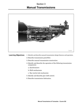
  • 1. Manual Transmissions & Transaxles – Course 302 1. Identify and describe manual transmission design features and operation. 2. Describe transmission powerflow. 3. Describe manual transmission construction. 4. Identify and describe the operation of the following transmission components: a. Synchronizers b. Shift mechanisms c. Key inertia lock mechanism 5. Identify and describe gear shift control. 6. Describe transmission lubrication. Section 3 Manual Transmissions Learning Objectives:
  • 2. Component Testing 2 TOYOTA Technical Training The manual transmission transfers power from the engine to the propeller shaft. It converts and multiplies rotational speed, allowing engine RPM to remain in it’s limited optimal power range while providing a wide range of RPM to the propeller shaft; which, in turn, controls vehicle speed. Multiple gear sets within the transmission provide gear ratios to best utilize the engine’s torque. A gear ratio of about 4:1 in first gear provides high torque to begin moving the vehicle. In contrast, a higher gear ratio of about 1:1 reduces engine speed at higher vehicle speeds when less torque is required to maintain momentum. Understanding manual transmission design features increases your knowledge of transmission operation, and provides for easier and more accurate problem diagnosis. The rear wheel drive transmission is constructed with three shafts, five forward gears, and a reverse gear. Transmission Components The rear wheel drive transmission is constructed with three shafts, five forward gears, and a reverse gear. The input shaftÄŠalso known as a main drive gear or clutch shaftÄŠis driven by the clutch disc and drives the counter gear shaft. The input shaft is supported by the pilot bearing at the end of the crankshaft and a bearing at the front of the transmission case. Section 3 Manual Transmissions Introduction Components Input Shaft
  • 3. TRX – ESP Troubleshooting Guide Manual Transmissions & Transaxles – Course 302 The counter gear shaftÄŠalso known as a cluster gearÄŠdrives the gears (1st, 2nd, 3rd, and 5th) on the output shaft. This shaft is supported by bearings in the intermediate plate, at the front of the transmission case, and in the extension housing. The output shaftÄŠalso known as the mainshaftÄŠdrives the propeller shaft. It is splined at the rear to allow a sliding connection to the propeller shaft. The output shaft gears rotate on the shaft and are locked to the shaft by synchronizers. The synchronizers are splined to the output shaft. The output shaft is supported by a pocket bearing at the rear of the input shaft, a bearing at the intermediate plate and a bearing at the extension housing of the transmission. Transmission Construction A rear wheel drive transmission has three sections: the clutch housing, the transmission case, and the extension housing. Counter Gear Shaft Output Shaft
  • 4. Component Testing 4 TOYOTA Technical Training Gears transfer engine power from the input shaft, through the counter gear shaft, to the output shaft. There are five forward gears and one reverse gear. Only one gear is engaged at a time. All forward motion gears are helical gears because of their smooth and quiet operating characteristics. Helical gears create end thrust under load, and therefore have a thrust surface on the side of the gear. Gear side clearance is limited to reduce noise and potential damage, which could result from gear motion. Reverse requires an additional gear in the gear train. A reverse idler gear is used to change the direction of the output shaft for reverse. The reverse gear is a straight cut spur gear and does not have a synchronizer. Spur gears are suitable for this application because they shift into mesh more easily than helical gears, and they don’t generate end thrust under load. Straight cut gears may create a whine or light growl during operation. Reverse Idler Gear An idler gear is used to change the direction of the output shaft for reverse. Gears Forward Gears Reverse Gears
  • 5. TRX – ESP Troubleshooting Guide Manual Transmissions & Transaxles – Course 302 Bearings and bushings are used to support shafts in the transmission. Depending upon design, transmissions use a wide variety of bearings, including: • Needle bearings ć can support large side loads but are unable to control end thrust loads. Individual needles are housed in a single enclosure or a split bearing holder. They are used in most forward speed gears. • Ball bearings ć can support moderate to high side and thrust loads and are commonly used for the input shaft and output shaft. • Roller bearings ć can support large side loads but are unable to control end thrust loads. Individual rollers are housed in a single enclosure. • Plain bushings ć can support large side loads and allow free inĆandĆout movement. Bushings are used on the reverse gear and to support the propeller shaft slip yoke in the extension housing. Transmission Bearings Depending upon design, transmissions use a wide variety of bearings. Bearings
  • 6. Component Testing 6 TOYOTA Technical Training Synchronizer assemblies are used to make all forward shifts and to assist reverse gear engagement. The role of the synchronizer is to allow smooth gear engagement. It acts as a clutch, bringing the gears and shaft to the same speed before engagement occurs. Synchronizer components help make the speeds equal while synchronizing the shift. Gears on the output shaft are in mesh (contact) with gears on the counter gear shaft at all times. Consequently, when the counter shaft turns, the gears on the output shaft rotate. When shifting gears, the synchronizer ring supplies the friction force, which causes the speed of the gear that is being engaged to match the speed of the hub sleeve. This allows the gear shift to occur without the gear and hub sleeve splines clashing or grinding. Synchronizer Assemblies Synchronizers are used to make all forward shifts and to assist with reverse. Synchronizer Assemblies
  • 7. TRX – ESP Troubleshooting Guide Manual Transmissions & Transaxles – Course 302 The synchronizer mechanism is constructed of the following components: • The speed gear is mounted on the output shaft. A needle roller bearing is installed between the speed gear and the output shaft, allowing the gear to rotate freely on the shaft. • The synchronizer ring ć also called a blocker ring ć is made of brass and is installed on the conical portion of the gear. Narrow grooves are cut in the inside area of the synchronizer ring to provide the necessary clutch action of the gear. Three equally spaced slots are cut on the outside surface for the synchronizer keys to fit into. • Two key springs are installed, one on each side of the clutch hub to hold the synchronizer keys in place against the hub sleeve. • The clutch hub is fit to the output shaft on splines and is secured by a snap ring. • Three synchronizer keys are installed in the three equally spaced slots in the clutch hub and are aligned with the slots in the synchronizer ring. • The hub sleeve has internal splines that slip over the clutch hub splines, engaging the spline teeth of the speed gear. An internal groove cut in the center of the hub sleeve splines centers the hub sleeve. The hub sleeve is indexed by the three spring loaded synchronizer keys. Synchronizer Components The Synchronizer is made up of the speed gear, synchronizer ring, synchronizer keys, key springs, clutch hub, and hub sleeve. Synchronizer Components
  • 8. Component Testing 8 TOYOTA Technical Training When the transmission is in neutral, the hub sleeve groove fits onto the synchronizer key detent. This allows the gears to free wheel on the output shaft. As the clutch pedal is depressed and the shift lever is moved into a gear, three stages are involved for the gearshift to occur. As the shift lever moves, the shift fork moves the hub sleeve to the right causing the springĆloaded keys to push the synchronizer ring against the cone clutch surface of the gear. Engagement of the synchronizer ring to the cone clutch on the faster spinning gear cause the synchronizer ring to rotate, about oneĆhalf the width of a spline. Rotation of the ring causes the sleeve to be out of alignment with the splines preventing further movement, while pressure applied to the cone clutch by the sleeve creates a braking action to slow the gear. Synchronized Gear Shift – 1st Stage When the transmission is in neutral, the synchronizer key detents hold the hub sleeve in the neutral position. Synchronizer Operation 1st Stage – Initial Synchronization
  • 9. TRX – ESP Troubleshooting Guide Manual Transmissions & Transaxles – Course 302 When the shift lever is moved further, the force (which is applied to the hub sleeve) overcomes the force of the synchronizer key springs. The hub sleeve moves over the detents of the keys. This movement also causes more pressure to be exerted on the synchronizer ring and gear. The grooves on the inside surface of the ring help to cut through the oil film on the conical surface of the gear. This ensures that the ring will provide the needed clutching action for engagement. The taper of the sleeve spline pushes against the taper of the ring teeth, causing added pressure to the gear cone. As the gear slows to the same speed as the hub and sleeve, it will rotate slightly backward to allow alignment of the splines. The synchronizer ring and gear splines line up at this time and the splines of the hub sleeve are ready to engage. Synchronized Gear Shift – 2nd Stage The taper of the sleeve spline pushes against the taper of the ring teeth to exert more pressure on the gear cone. 2nd Stage – Synchronization
  • 10. Component Testing 10 TOYOTA Technical Training When the speeds of the hub sleeve and the gear become equal, the synchronizer ring is not in contact with the key. The ring and gear are free to move and the splines of the hub sleeve can engage smoothly. The sleeve continues to move over the splines of the speed gear, locking the key to the gear, completing gear engagement. Synchronized Gear Shift – 3rd Stage When the speed of the hub sleeve and the gear become equal the hub sleeve engages the splines of the gear. 3rd Stage – Synchronized Meshing
  • 11. TRX – ESP Troubleshooting Guide Manual Transmissions & Transaxles – Course 302 Synchronizer hub sleeves have a slight back cut at the ends of the splines. This cut matches a similar cut on the spline gear teeth of the speed gears. This locks the gears in engagement and prevents the sleeve from jumping out of mesh. Synchronizer Hub Sleeve and Splines Hub sleeve splines are back cut to lock the gears in engagement, preventing the sleeve from jumping out of mesh. Synchronizer Hub Sleeve & Splines
  • 12. Component Testing 12 TOYOTA Technical Training Splines of different thickness have been used where the gears fit into the hub sleeve to increase the meshing pressure (surface pressure) of the hub and gears, and to prevent the sleeve from jumping out of engagement. As a result, when driving torque is transmitted from a gear to the hub sleeve, all of the splines of the gear mesh with the hub sleeve, but during engine braking (driving torque transmitted from the hub sleeve to the gears), the number of gear splines meshing with the hub sleeve decreases. This causes the meshing pressure of the hub sleeve and the gear to increase, thus preventing the sleeve from jumping out of engagement. Inertia Lock During engine braking, the number of hub splines in contact with the gear splines is reduced causing more pressure to be exerted on the splines still in contact. Inertia Lock
  • 13. TRX – ESP Troubleshooting Guide Manual Transmissions & Transaxles – Course 302 Some transmissions use two or three cone synchronizer units. Multiple cone synchronizers have more surface area available to provide low shift effort for the lower gear ranges. The two cone synchronizer is so named from the two cone shaped surfaces which make up the assembly. The middle ring provides two cone surfaces and almost twice the surface area to slow the gear to the speed of the output shaft. In a twoĆcone synchronizer, the inner and outer rings are indexed together and turn with the transmission output shaft. The middle ring is indexed to the gear and they turn together driven by the input shaft. During shifting, the hub sleeve pushes the synchronizer keys against the outer ring. The inside surface of the outer ring mates with the outside surface of the middle ring creating one friction surface. The inside surface of the middle ring mates with the outside surface of the inner ring providing the second friction surface. Two-Cone Synchronizer In a two-cone synchronizer, the inner and outer rings turn with the transmission output shaft. The middle ring and gear turn together driven by the input shaft. Multi-Cone Synchronizer Two-Cone Synchronizer
  • 14. Component Testing 14 TOYOTA Technical Training The three cone synchronizer is so named from the three cone shaped surfaces which make up the assembly. In addition to the middle ring providing two cone surfaces, the speed gear has a third cone surface providing three surface areas to slow the gear to the speed of the output shaft. In a threeĆcone synchronizer, the inner and outer rings turn with the transmission output shaft. The middle ring is indexed to the gear and they turn together driven by the input shaft. During shifting, the hub sleeve pushes the synchronizer keys against the outer ring. The inside surface of the outer ring mates with the outside surface of the middle ring creating one friction surface. The inside surface of the middle ring mates with the outside surface of the inner ring providing the second friction surface. The inside surface of the inner ring mates with the cone surface of the speed gear providing the third friction surface. Three-Cone Synchronizer In a three-cone synchronizer, the inner and outer rings turn with the transmission output shaft. The middle ring is indexed to the gear and they turn together driven by the input shaft. Understanding the powerflow through a transmission helps the technician in diagnosing complaints and determining the proper repairs to be done. The following illustrations show the typical powerflow through a fiveĆspeed transmission. For example, in first gear, power flows from the input shaft and main drive gear to the counter shaft. First gear, on the counter shaft, drives first gear on the output shaft. The first gear is locked to the synchronizer clutch hub transmitting power to the output shaft. On the following three pages, in figures 3Ć14 through figure 3Ć19, the powerflow for 1st, 2nd, 3rd, 4th, 5th, and Reverse are highlighted and traced through a transmission. Three-Cone Synchronizer Transmission Powerflow
  • 15. TRX – ESP Troubleshooting Guide Manual Transmissions & Transaxles – Course 302 1st Gear 2nd Gear
  • 16. Component Testing 16 TOYOTA Technical Training 3rd Gear 4th Gear
  • 17. TRX – ESP Troubleshooting Guide Manual Transmissions & Transaxles – Course 302 5th Gear Reverse Gear
  • 18. Component Testing 18 TOYOTA Technical Training The gear shift lever and internal linkage allow the transmission to be shifted through the gears. The shift lever is mounted in the transmission extension housing and pivots on a ball socket. The shift fork shaft connects the shift lever to the shift forks. A detent ball and spring prevent the forks from moving on their own. The shift forks are used to lock and unlock the synchronizer hub sleeve and are mounted on the shafts either by bolts or roll pins. The shift forks ride in the grooves of the synchronizer hub sleeves. Shift forks contact the spinning synchronizer sleeve and apply pressure to engage the gear. To reduce wear, the steel or aluminum forks can have contact surfaces of hardened steel, bronze, lowĆfriction plastic, or a nylon pad attached to the fork. After the sleeve has been positioned, there should be very little contact between the fork and sleeve. The fork is properly positioned by the detent. The back taper of the hub sleeve splines and spline gear, and gear inertia lock mechanism, keep it in mesh during different driving conditions. Holding a gear into mesh with the fork results in rapid wear of the fork and hub sleeve groove. Wear at the shift lever ball socket, shift fork shaft bushings, and shift fork contact surfaces may cause the synchronizer sleeve to be improperly positioned, causing the sleeve to jump out of gear. Gear Shift Mechanism The gear shift mechanism includes the shift lever, shift fork shafts, shift forks, and shift detents. Gear Shift Mechanism
  • 19. TRX – ESP Troubleshooting Guide Manual Transmissions & Transaxles – Course 302 Other mechanisms that make up gear shift control are the: • Shift detent mechanism • Shift interlock mechanism • MisĆshift prevention • Reverse misĆshift prevention • Reverse preĆbalk mechanism • Shift detent mechanism • Reverse oneĆway mechanism Detents locate the internal shift forks in one of their three positions. The detent ball rides in one of three notches cut into the shift fork shaft. The center detent position is neutral. Moving the shift shaft to a detent on either side of center engages a speed gear. When the shaft is moved either forward or backward, the ball rides on the shaft and is forced into a notch by the spring. The spring holds the ball secure in the notch and will not let the shaft move unless the shift lever applies enough force to overcome the spring tension. Shift Detent Mechanism The detent ball rides in one of three notches cut into the shift fork shaft. The shift interlock prevents engaging more than one gear at a time. A set of pins hold the other shift fork shafts in place when one of the shafts has been moved by the shift lever. This operation insures that the transmission will not be shifted into two gears at the same time. Shift Detent Mechanism Shift Interlock Mechanism
  • 20. Component Testing 20 TOYOTA Technical Training Shift Interlock Mechanism A set of interlock pins hold the other shift fork shafts in place when the shift lever moves one of the shafts. When shift fork shaft No. 1 is moved to the left, the two interlock pins are pushed out by the shaft and into the slots on the other shafts. As a result, shafts two and three are locked in position. When shift fork shaft No. 2 is moved to the left, the two interlock pins are pushed out by the shaft and into the slots on the other shafts. As a result, shafts one and three are locked in position. When shift fork shaft No. 3 is moved to the left, the two interlock pins are pushed out by the shaft and into the slots on the other shafts. As a result, shafts one and two are locked in position. Shift Fork Shafts and Interlock Pins When a shift fork shaft is moved to the left, the two interlock pins are pushed out, locking the other two shafts in position. Shaft Locking
  • 21. TRX – ESP Troubleshooting Guide Manual Transmissions & Transaxles – Course 302 The misĆshift prevention mechanism is located in the transmission extension housing. The shift lever is spring loaded to provide the driver with a sense of the shift lever position during shifting, Shift restrict pins are installed on opposite sides of the extension housing adjacent to the shift lever. The pins contain springs of different tension and are color coded for that reason. The restrict pins ensure that the shift lever is always pushed toward the 3rd and 4th gear select position. When shifting from 2nd to 3rd gear, the pins will help the driver engage 3rd gear and not 1st. Mis-Shift Prevention Upshift Shift restrict pins have different tension and push the shift lever toward the third and fourth gear select position. The reverse restrict pin is located in the extension housing and prevents the driver from down shifting from 5th gear into reverse by stopping the travel of the shift and select lever. When the transmission is shifted into 5th gear, the shift and select lever passes by the reverse restrict pin. Mis-Shift Prevention Mis-Shift Prevention Upshift Reverse Mis-Shift Prevention
  • 22. Component Testing 22 TOYOTA Technical Training When shifting out of fifth gear the lever will contact the protrusion on the restrict pin, compress the spring on the shaft and force the pin against the stop. The shift and select lever is not allowed past the neutral position and into reverse gear. When shifting into reverse, the shift and select lever contacts the restrict pin protrusion, rotates the pin on the shaft and causes the spring to coil tighter. The lever can now move the required parts to engage reverse gear. The spring tension is relieved when the lever is moved to the neutral position and the restrict pin returns to original position. Reverse Mis- Shift Prevention The reverse restrict pin prevents the driver from down shifting from 5th gear into reverse by stopping the travel of the shift and select lever. Shifting into Reverse
  • 23. TRX – ESP Troubleshooting Guide Manual Transmissions & Transaxles – Course 302 The reverse preĆbalk mechanism utilizes the fifth gear synchronizer assembly on the countershaft to reduce gear clash when shifting into reverse. By engaging the fifth synchronizer ring the input shaft, counter gear shaft and speed gears are slowed allowing the reverse idler gear and the reverse gears to engage with a minimum gear clash. The synchronizer assembly components include the following: • Reverse synchronizer ring • 5th synchronizer hub sleeve (hub sleeve No. 3) • 5th synchronizer ring • Synchronizer cone ring • Reverse synchronizer pull ring • Gear spline piece No. 5 The synchronizer cone ring is indexed to the gear spline piece that is pressed to the counter gear shaft. It is the cone that the 5th synchronizer ring contacts when shifting into 5th gear or reverse. Reverse Pre-Balk Mechanism The fifth gear synchronizer assembly on the countershaft is used to reduce gear clash when shifting into reverse. The synchronizer assembly is held together with the reverse synchronizer pull ring tabs locked to the reverse synchronizer ring. The synchronizer cone ring and 5th synchronizer ring are located between these two parts and cause the braking action to slow the counter gear shaft and speed gears. Reverse Pre-Balk Mechanism
  • 24. Component Testing 24 TOYOTA Technical Training When shifting into reverse the 5th synchronizer hub sleeve is moved to the left and moves the reverse synchronizer ring and shifting keys. As with the key type synchronizer covered earlier, the reverse synchronizer ring rotates slightly causing the misalignment of the synchronizer spline teeth and the hub sleeve splines. As the taper on the front of the reverse synchronizer ring and hub sleeve splines make contact, greater force is applied to the reverse synchronizer ring and reverse synchronizer pull ring. The pull ring pulls the synchronizer cone ring into engagement with the 5th synchronizer ring, slowing the counter gear shaft and speed gears on the output shaft. Synchronizer Rings The synchronizer assembly is held together with the reverse synchronizer pull ring tabs locked to the reverse synchronizer ring.
  • 25. TRX – ESP Troubleshooting Guide Manual Transmissions & Transaxles – Course 302 The reverse oneĆway mechanism on the R and W series transmissions allows 5th gear and reverse to be selected using the same shift fork shaft. The reverse oneĆway mechanism prevents the movement of the reverse shift fork while shifting in or out of 5th gear. This is accomplished with the use of a snap ring and an interlock ball or pin. The interlock ball/pin is located in the reverse shift fork between shift fork shaft No. 3 and shift fork shaft No. 4. The snap ring is installed on shift fork shaft No. 3, between the intermediate plate and the reverse shift fork. Shift fork shaft No. 4 is a stationary shaft that is locked to the transmissions intermediate plate. Reverse One-Way Mechanism The interlock pin is located in the reverse shift fork between the two shift fork shafts. When 5th gear is selected, shift fork shaft No. 3 is moved to the right. The interlock ball is pushed into the notch in shift fork shaft No. 4, locking the reverse shift fork to the shaft. The reverse shift fork can only move into reverse when shift fork shaft No. 3 is in the neutral position. When shifting into reverse, shift fork shaft No. 3 moves to the left causing the snap ring to move the reverse shift fork. As the shift fork moves over shift fork shaft No. 4, the interlock ball moves into the notch of shift fork shaft No. 3, locking the shift fork to shaft No. 3. Reverse One-Way Mechanism Operation
  • 26. Component Testing 26 TOYOTA Technical Training When shifting out of reverse, shift fork shaft No.3 moves to the right and the reverse shift fork also moves to the right. If the interlock ball were not installed during reassembly, the transmission would remain in reverse with no way to disengage reverse gear as it is held in position by its detent ball and spring. Selecting a forward gear and engaging the clutch will cause the engine to stall because two gears are engaged at the same time. Reverse One-Way Mechanism Operation
  • 27. TRX – ESP Troubleshooting Guide Manual Transmissions & Transaxles – Course 302 To prevent overheating, the lower transmission gears run in a bath of lubricant. As they spin, their motion spreads the lubricant throughout the case. Floating gears on the mainshaft or counter shaft of R series transmissions have oil passages drilled to get lubricant into critical areas. Some transmissions use scoops, troughs, or oiling funnels as lubrication paths. Each transmission includes a vent at the top, to relieve internal pressure (heat) during operation. The transmission gears are lubricated to: • Reduce friction • Transfer heat away from gears and bearings • Reduce corrosion and rust • Remove dirt and wear particles from moving parts The Society of Automotive Engineers (SAE) and the American Petroleum Institute (API) Service Classification provide rating systems for selection of proper lubricants for particular uses. Viscosity is a measurement of fluid thickness and is determined by how fast a fluid runs through a precisely sized orifice at a particular temperature. The following are API gear oil classifications: • GLĆ1: Straight mineral oil; used in nonĆsynchromesh transmissions; use additives; not suitable for modern automobile transmissions • GLĆ2: A designation for worn gear drives used in mostly industrial applications • GLĆ3: Contains mild EP additives; used in manual transmissions and transaxles with spiral bevel final drives • GLĆ4: Used in manual transmissions and transaxles with hypoid final drives; contains half the additives found in GLĆ5 • GLĆ5: Contains enough EP additive to lubricate hypoid gears in drive axles An additional classification, GLS (Gear Lubricant Special), is sometimes used to indicate a proprietary set of specifications determined by the vehicle or gearbox manufacturer. Transmission Lubrication Gear Lubrication
  • 28. Component Testing 28 TOYOTA Technical Training Toyota manual transmissions use the following gear lubrication types: • 75WĆ90 GL4/GL5 • 80WĆ90 GL4/GL5 • TOYOTA V160 (Supra 6ĆSpeed V160MT) Consult the vehicle repair manual for specific lubrication information. Toyota transmission cases use FormedĆInĆPlace Gaskets (FIPG). FIPG gaskets are usually RoomĆTemperature Vulcanizing (RTV) or anaerobic sealants. RTV sealant is made from silicone and is one of the most widely used gasket compounds. It is extremely thick, and sets up to a rubberĆlike material very quickly when exposed to air. Anaerobic sealant is similar in function to RTV. It can be used either to seal gaskets or to form gaskets by itself. Unlike RTV, anaerobic sealant cures only in the absence of air. This means that an anaerobic sealant cures only after the assembly of parts, sealing them together. Gear Lubrication Types Case Sealants
  • 29. TRX – ESP Troubleshooting Guide Manual Transmissions & Transaxles – Course 302