College Call Girls Nashik Nehal 7001305949 Independent Escort Service Nashik
Abrasive jet machining
1. Abrasive Jet Machining (AJM)
Abrasive Jet Machining (AJM), also known as micro-abrasive blasting, is a mechanical
energy based unconventional machining process used to remove unwanted material from a
given workpiece.
The process makes use of an abrasive jet with high velocity, to remove material and
provide smooth surface finish to hard metallic workpieces. It is similar to Water Jet
Machining (WJM).
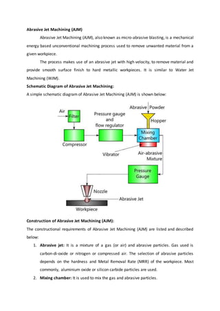
Schematic Diagram of Abrasive Jet Machining:
A simple schematic diagram of Abrasive Jet Machining (AJM) is shown below:
Construction of Abrasive Jet Machining (AJM):
The constructional requirements of Abrasive Jet Machining (AJM) are listed and described
below:
1. Abrasive jet: It is a mixture of a gas (or air) and abrasive particles. Gas used is
carbon-di-oxide or nitrogen or compressed air. The selection of abrasive particles
depends on the hardness and Metal Removal Rate (MRR) of the workpiece. Most
commonly, aluminium oxide or silicon carbide particles are used.
2. Mixing chamber: It is used to mix the gas and abrasive particles.
2. 3. Filter: It filters the gas before entering the compressor and mixing chamber.
4. Compressor: It pressurizes the gas.
5. Hopper: Hopper is used for feeding the abrasive powder.
6. Pressure gauges and flow regulators: They are used to control the pressure and
regulate the flow rate of abrasive jet.
7. Vibrator: It is provided below the mixing chamber. It controls the abrasive powder
feed rate in the mixing chamber.
8. Nozzle: It forces the abrasive jet over the workpiece. Nozzle is made of hard and
resistant material like tungsten carbide.
Working:
Dry air or gas is filtered and compressed by passing it through the filter and compressor.
A pressure gauge and a flow regulator are used to control the pressure and regulate the
flow rate of the compressed air.
Compressed air is then passed into the mixing chamber. In the mixing chamber, abrasive
powder is fed. A vibrator is used to control the feed of the abrasive powder. The
abrasive powder and the compressed air are thoroughly mixed in the chamber. The
pressure of this mixture is regulated and sent to nozzle.
The nozzle increases the velocity of the mixture at the expense of its pressure. A fine
abrasive jet is rendered by the nozzle. This jet is used to remove unwanted material
from the workpiece.
For a good understanding of construction and working of AJM, refer the schematic
diagram above.
Operations that can be performed using Abrasive Jet Machining (AJM):
The following are some of the operations that can be performed using Abrasive Jet
Machining:
1. Drilling
2. Boring
3. Surface finishing
4. Cutting
5. Cleaning
6. Deburring
7. Etching
8. Trimming
9. Milling
Advantages of Abrasive Jet Machining:
Surface of the workpiece is cleaned automatically.
3. Smooth surface finish can be obtained.
Equipment cost is low.
Hard materials and materials of high strength can be easily machined.
Disadvantages of Abrasive Jet Machining:
Metal removal rate is low
In certain circumstances, abrasive particles might settle over the workpiece.
Nozzle life is less. Nozzle should be maintained periodically.
Abrasive Jet Machining cannot be used to machine soft materials.
Process Parameters of Abrasive Jet Machining
Process parameters of Abrasive Jet Maching (AJM) are factors that influence its
Metal Removal Rate (MRR).
In a machining process, Metal Removal Rate (MRR) is the volume of metal removed
from a given workpiece in unit time.
The following are some of the important process parameters of abrasive jet machining:
1. Abrasive mass flow rate
2. Nozzle tip distance
3. Gas Pressure
4. Velocity of abrasive particles
5. Mixing ratio
6. Abrasive grain size
Abrasive mass flow rate:
Mass flow rate of the abrasive particles is a major process parameter that influences the
metal removal rate in abrasive jet machining.
In AJM, mass flow rate of the gas (or air) in abrasive jet is inversely proportional to the
mass flow rate of the abrasive particles.
Due to this fact, when continuously increasing the abrasive mass flow rate, Metal
Removal Rate (MRR) first increases to an optimum value (because of increase in number
of abrasive particles hitting the workpiece) and then decreases.
However, if the mixing ratio is kept constant, Metal Removal Rate (MRR) uniformly
increases with increase in abrasive mass flow rate.
Nozzle tip distance:
Nozzle Tip Distance (NTD) is the gap provided between the nozzle tip and the workpiece.
Upto a certain limit, Metal Removal Rate (MRR) increases with increase in nozzle tip
distance. After that limit, MRR remains constant to some extent and then decreases.
4. In addition to metal removal rate, nozzle tip distance influences the shape and diameter
of cut.
For optimal performance, a nozzle tip distance of 0.25 to 0.75 mm is provided.
Gas pressure:
Air or gas pressure has a direct impact on metal removal rate.
In abrasive jet machining, metal removal rate is directly proportional to air or gas
pressure.
Velocity of abrasive particles:
Whenever the velocity of abrasive particles is increased, the speed at which the
abrasive particles hit the workpiece is increased. Because of this reason, in abrasive jet
machining, metal removal rate increases with increase in velocity of abrasive particles.
Mixing ratio:
Mixing ratio is a ratio that determines the quality of the air-abrasive mixture in Abrasive
Jet Machining (AJM).
It is the ratio between the mass flow rate of abrasive particles and the mass flow rate of
air (or gas).
When mixing ratio is increased continuously, metal removal rate first increases to some
extent and then decreases.
Abrasive grain size:
Size of the abrasive particle determines the speed at which metal is removed.
If smooth and fine surface finish is to be obtained, abrasive particle with small grain size
is used.
If metal has to be removed rapidly, abrasive particle with large grain size is used.
Water Jet Machining (WJM)
Water Jet Machining (WJM) is a mechanical energy based non-traditional machining
process used to cut and machine soft and non-metallic materials.
It involves the use of high velocity water jet to smoothly cut a soft workpiece. It is similar
to Abrasive Jet Machining (AJM).
5. In water jet machining, high velocity water jet is allowed to strike a given workpiece.
During this process, its kinetic energy is converted to pressure energy. This induces a
stress on the workpiece. When this induced stress is high enough, unwanted particles of
the workpiece are automatically removed.
Schematic diagram of Water Jet Machining:
Construction of Water Jet Machining (WJM):
The apparatus of water jet machining consists of the following components:
1. Reservoir: It is used for storing water that is to be used in the machining operation.
2. Pump: It pumps the water from the reservoir.
3. Intensifier: It is connected to the pump. It pressurizes the water acquired from the
pump to a desired level.
4. Accumulator: It is used for temporarily storing the pressurized water. It is connected
to the flow regulator through a control valve.
5. Control Valve: It controls the direction and pressure of pressurized water that is to
be supplied to the nozzle.
6. Flow regulator: It is used to regulate the flow of water.
7. Nozzle: It renders the pressurized water as a water jet at high velocity.
6. Working of Water Jet Machining (WJM):
Water from the reservoir is pumped to the intensifier using a hydraulic pump.
The intensifier increases the pressure of the water to the required level. Usually, the
water is pressurized to 200 to 400 MPa.
Pressurized water is then sent to the accumulator. The accumulator temporarily
stores the pressurized water.
Pressurized water then enters the nozzle by passing through the control valve and
flow regulator.
Control valve controls the direction of water and limits the pressure of water under
permissible limits.
Flow regulator regulates and controls the flow rate of water.
Pressurized water finally enters the nozzle. Here, it expands with a tremendous
increase in its kinetic energy. High velocity water jet is produced by the nozzle.
When this water jet strikes the workpiece, stresses are induced. These stresses are
used to remove material from the workpiece.
The water used in water jet machining may or may not be used with stabilizers.
Stabilizers are substances that improve the quality of water jet by preventing its
fragmentation.
For a good understanding of water jet machining, refer the schematic diagram
above.
Advantages of Water Jet Machining (WJM):
1. Water jet machining is a relatively fast process.
2. It prevents the formation of heat affected zones on the workpiece.
3. It automatically cleans the surface of the workpiece.
4. WJM has excellent precision. Tolerances of the order of ±0.005″ can be obtained.
5. It does not produce any hazardous gas.
6. It is eco-friendly.
Disadvantages of Water Jet Machining:
1. Only soft materials can be machined.
2. Very thick materials cannot be easily machined.
3. Initial investment is high.
7. Applications of Water Jet Machining:
1. Water jet machining is used to cut thin non-metallic sheets.
2. It is used to cut rubber, wood, ceramics and many other soft materials.
3. It is used for machining circuit boards.
4. It is used in food industry.
ULTRASONIC MACHINING PROCESS (USM)
PRINCIPLE OF ULTRASONIC MACHINING PROCESS (USM):
Ultrasonic machining (USM) is the elimination of material by the abrading action of
micro stones-loaded liquid slurry available between the work piece and a tool which
is vibrating at a 90 degree angle to the work surface at a frequency more than the
audible range.
USM, also known as ultrasonic collision grinding, is a machining operation in which
abrasive slurry particles are generously flows between the work piece and a vibrating
tool.
This process varies from most other machining methods since in this process a very
little amount of heat is generated on the work piece.
The tool material will not contacts the work material and as a result the grinding
force is infrequently more, which makes this operation perfect for machining
tremendously hard and brittle materials, such as glass, ruby, graphite, diamond,
sapphire and ceramics.
The workingcourse of action of an ultrasonicmachiningisdone whenthe tool interactswith
the work piece or the medium to be treated.
The tool is subjected to vibration in a particular direction, frequency and intensity.
The vibrations are produced by a transducer and are transmitted to the tool using a
vibration transmission system, often with an alteration in direction and amplitude.
The structure of the ultrasonicmachine isdependentonthe process being performed by its
tool.
CHARACTERISTICS OF ULTRASONIC MACHINING PROCESS (USM):
i. The USM process is done by selecting a desirable tool along-with abrasives slurry as a
working media.
8. ii. Generally the cutting tool oscillates at the frequency range of 20 KHZ to 40 KHZ.
iii. Always the shape of tool is similar to the shape requirements in the work piece.
iv. The abrasive grains are actuated by the high speed reciprocate motions across the small
gap, in between the tool and the work piece.
v. Uniform force is applied to progressively feed the tool.
vi. The impact of abrasive particles is the energy source which is mainly responsible in
removal of the material, through the form of small wear particles which are carried away by
the abrasive slurry.
USM PROCESS:
Ultrasonic Machining consists of:
1. High Power sine wave generator
2. Magneto- striction Transducer
3. Tool Holder
4. Tool
Ultrasonic Machining Process
The magnetostrictor used in USM, is shown in above figure has a high-frequency
winding wound on a magnetostrictor core and a special polarizing winding around an
armature. The magnetostriction effect was first exposed by Joule at Manchester in the year
of 1874. Magnetic field undergoing ultrasonic frequencies causes corresponding changes in
a ferromagnetic object placed within its region of influence.
9. This outcome is used to oscillate the USM tool, which is mounted at the last part of a
magnetostrictor, at ultrasonic frequencies (18 to 20 kHz). The method of action of a
magnetostrictor can be explained as follows.
Coefficient of magnetostriction elongation is calculated by using the following formula (em)=
(∆l/l )
Here, Δl – Incremental length of the magnetostrictor (mm)
l- Length of the magnetostrictor core (mm)
Process parameters of USM:
1. Amplitude of vibration (15 to 50 microns)
2. Frequency of vibration (19 to 25 kHz).
3. Feed force (F) related to tool dimensions.
4. Feed pressure.
5. Abrasive size.
6. Abrasive materials: (Al203, SiC, B4C, Boron silicarbide, Diamond)
7. Flow strength of the work material.
8. Flow strength of the tool material.
9. Contact area of the tool.
10. Volume concentration of abrasive in water slurry.
11. Tool characteristics:
a. Material of tool
b. Shape
c. Amplitude of vibration
d. Frequency of vibration
e. Strength developed in tool
12. Work material characteristics:
a. Material
b. Impact strength
c. Surface fatigue strength
13. Slurry material characteristics:
a. Abrasive – hardness, size, shape and quantity of abrasive flow
b. Liquid – Chemical property, viscosity, and flow rate.
c. Pressure.
10. d. Density.
ADVANTAGES OF ULTRASONIC MACHINING PROCESS:
i. There is no direct contact of the tool and workpiece. since the slurry used, it makes it a
wet cutting process.
ii. The surfaces produced are free from stress and damages.
iii. Free from burrs and distortions.
iv. suitable for machining brittle materials
v. Good surface finish and structural integrity.
APPLICATIONS OF ULTRASONIC MACHINING PROCESS:
i. This process is capable on hard and brittle alloys, semiconductors, glass, fiber material,
Ceramics, carbides etc.
ii. Machining on auto-engine components.
iii. In machining, wire drawing, punching and blanking of small dies are possible one.
iv. Machining ceramic components for drilling holes in borosilicate glass for the sensors used
in electronic industries.
v. Drilling very fine holes in helicopter power transmission shafts and gears.
DISADVANTAGES AND LIMITATIONS OF ULTRASONIC MACHINING PROCESS:
i. Very poor material removal rate.
ii. Relatively high tool wear.
iii. Minimum depth of hole is achieved.