
Recommended
More Related Content
What's hot
What's hot (20)
Similar to fluid mechanics exp. Flow rate
Similar to fluid mechanics exp. Flow rate (20)
More from Muhammed Fuad Al-Barznji
More from Muhammed Fuad Al-Barznji (20)
Recently uploaded
Recently uploaded (20)
fluid mechanics exp. Flow rate
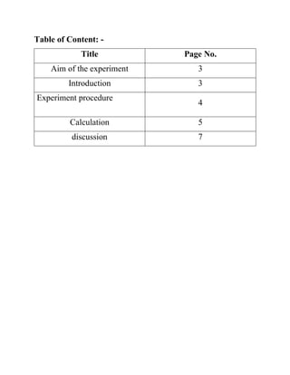
- 1. Table of Content: - Title Page No. Aim of the experiment 3 Introduction 3 Experiment procedure 4 Calculation 5 discussion 7
- 2. Aim of the experiment:- Measuring the fluid flow rate. Introduction:- The basic Hydraulics Bench and the various ancillary modules available form a comprehensive laboratory facility which enables a detailed Mechanics of Fluids Laboratory. The hydraulics bench unit provides the basic services for the pumping and volumetric measurement of the water supply with which all the additional accessories and experiments are used. The working surface of the unit is in fiberglass, molded to provide a recessed area on which to mount experiments. An integral weir tank is provided along with a volumetric measuring tank. The measuring tank is stepped to enable for accurate measuring of both high and low flow rates. A level indicator allows convenient read out of the flow. The measuring tank discharges into a fiberglass sump tank via a valve. Overflow pipe is provided. An electric motor drives a submersible motor driven pump which delivers water to the outlet at the working surface for connection to the individual experiments. 1- Volumetric measuring tank with channel 2-Remote sight gauge 3- Sliding valve 4- Sump tank 5- Drain cock 6- Submersible motor driven pump 7- Water supply for accessories with pump 8- Flow control valve 9- Overflow pipe 10- Switch box 11- Discharge cap 12- Water supply connection for accessories without pump
- 3. Experiment procedure * Turn on the pump. * Set the stop watch to zero. * Close the valve at the bottom of the volumetric tank, wait until the liquid reaches a value of 10 liters and at the same start the watch. * After the liquid reached a value of 20 liters stop the watch. * Read off and note the measurement time and the high value of water in tank. Table of readings No. V (liter) t (s) 1 10 23.7 2 10 16.01 3 10 12.86
- 4. Calculation: - No.1/ 1L=0.001m3 -Volume flow rate t V Q 7.23 01.0 Q =0.000422 m3/s -Mass Flow rate Qm m=1000*0.000442 m=0.421941 kg/s - Weight flow rate gQW W =1000*9.81*0.000442 W = 4.139241 N/s NO.2 -Volume flow rate t V Q =0.000246 m3/s -Mass Flow rate Qm m=1000*0.000246 m=0.6246 kg/s - Weight flow rate gQW W =1000*9.81*0.000442 W = 6.12374 N/s 01.16 01.0 Q
- 5. No.3 Volume flow rate t V Q 86.12 01.0 Q =0.000777 m3 /s -Mass Flow rate Qm m=1000*0.000777 m=0.7776 kg/s - Weight flow rate gQW W =1000*9.81*0.000777 W = 7.6283 N/s Table of Calculating: - No. V (m3 ) t (s) Q ( s m3 ) m ( s kg ) W ( s N ) 1 10 23.7 0.000422 0.421941 4.139241 2 10 16.01 0.000246 0.6246 6.12374 3 10 12.86 0.000777 0.7776 7.6283
- 6. Discussion: - Q1/ Draw the relation between Q & m , then find the slop of the relation? A/ 0.4 0.45 0.5 0.55 0.6 0.65 0.7 0.75 0.8 0.0004 0.00045 0.0005 0.00055 0.0006 0.00065 0.0007 0.00075 0.0008 Volume flow rate (Q) MassFlowrate(m)
- 7. Q2/ Draw the relation between Q & W , then find the slop of the relation? A/ Q3- What do you understand by the slops above? A/ By increasing volume flow rate, the mass flow rate will increase and the time will decrease. 0.4 0.45 0.5 0.55 0.6 0.65 0.7 0.75 0.8 0.0004 0.00045 0.0005 0.00055 0.0006 0.00065 0.0007 0.00075 0.0008 Volume flow rate (Q) WeightFlowrate(W)