SlideShare a Scribd company logo
1 of 9
Download to read offline
C
Ci
iv
vi
il
l E
En
ng
gi
in
ne
ee
er
ri
in
ng
g F
Fa
ac
cu
ul
lt
ty
y W
WA
AT
TE
ER
R R
RE
ES
SO
OU
UR
RC
CE
ES
S E
EN
NG
GI
IN
NE
EE
ER
RI
IN
NG
G
C
Ci
iv
vi
il
l E
En
ng
gi
in
ne
ee
er
ri
in
ng
g D
De
ep
pa
ar
rt
tm
me
en
nt
t
H
Hy
yd
dr
ra
au
ul
li
ic
cs
s 2
20
01
11
1-
-F
FA
AL
LL
L
E
EX
XE
ER
RC
CI
IS
SE
ES
S 2
2-
- D
DA
AM
MS
S -
- A
AC
CT
TI
IN
NG
G F
FO
OR
RC
CE
ES
S
Abdüsselam ALTUNKAYNAK www.altunkaynak.net
Research Assist. İsmail DABANLI www.akademi.itu.edu.tr/dabanli
PROBLEM 1 Analyze the stability of given gravity dam (Figure 1) for the following conditions: Friction coefficient between
concrete-foundation is 0.70, respectively. Allowable shear stress at the foundation level is 2200 kN/m2
, allowable compressive and
shear stresses in concrete are 2700 kN/m2
, and 2400 kN/m2
, respectively. Allowable compressive stress in foundation material is
2700 kN/m2
. Take specific weights of concrete and water as 24 kN/m3
, and 10 kN/m3
, respectively.
PROBLEM 2 Analyze the stability of given gravity dam (Figure 2) for the following conditions: The ice tickhness at the resevoir
surface is 50 cm with the increase in temperature of 5 o
C/h. Friction coefficients between concretes, and concrete-foundation are
0.75 and 0.65, respectively. Allowable shear stress at the foundation level is 2000 kN7m2
, allowable compressive and shear stress
in concrete are 2500 kN/m2
, and 2200 kN/m2
, respectively. Allowable compressive stress in foundation material is 2500 kN/m2
.
Relief drainage may reduce the uplift force by 50 %. The earthquake coefficient is 0.1. Take specific weights of concrete and water
as 25 kN/m3
, and 10 kN/m3
, respectively.
PROBLEM 3 Determine the total volume of an arch dam 120 m high to span a 300 m wide U-shaped valley. The crest width is 6
m. Take  = 10 kN/m3
,  = 120o
, all = 6200 kN/m2
. Ignore the variation of span width and a in the vertical direction. Consider
vertical upstream face.
PROBLEM 4 Determine the optimum central angle of an arch dam giving the minimum volume of rib.
Answer :a = 133o
.34’
PROBLEM 5 Elevation of an arch dam (Figure 3) is 75 m. Span (top width) of a U-shaped valley is 350 m. Central angle is 150o
.
Allowable compressive stress in concrete is 5500 kN/m2
. Ignoring the variation of , and span width with respect to depth,
determine:
a) The cross-section for a vertical upstream faced arch dam having 6 m thickness at the crest,
b) Thickness of arch at 30 m below the water surface,
c) Volume of arch per unit height assuming 1 m unit height at the bottom,
d) Total volume of arch dam
In the computations, take con = 24 kN/m3
, and w = 10 kN/m3
hx
6 m
tb
75 m
70 m
6 m 4 m 45 m
55 m
O
65 m
Figure 1
Figure 3
Figure 2
55 m
6 m 5 m 30 m
41 m
O
50 m
0.7 H : 1 V
1 H : 10 V
15 m
C
Ci
iv
vi
il
l E
En
ng
gi
in
ne
ee
er
ri
in
ng
g F
Fa
ac
cu
ul
lt
ty
y W
WA
AT
TE
ER
R R
RE
ES
SO
OU
UR
RC
CE
ES
S E
EN
NG
GI
IN
NE
EE
ER
RI
IN
NG
G
C
Ci
iv
vi
il
l E
En
ng
gi
in
ne
ee
er
ri
in
ng
g D
De
ep
pa
ar
rt
tm
me
en
nt
t
H
Hy
yd
dr
ra
au
ul
li
ic
cs
s 2
20
01
11
1-
-F
FA
AL
LL
L
E
EX
XE
ER
RC
CI
IS
SE
ES
S 2
2-
- D
DA
AM
MS
S -
- A
AC
CT
TI
IN
NG
G F
FO
OR
RC
CE
ES
S
Abdüsselam ALTUNKAYNAK www.altunkaynak.net
Research Assist. İsmail DABANLI www.akademi.itu.edu.tr/dabanli
SOLUTION 1
 Forces and loads acting the dam:
Fwh: Hydrostatic force produced by water in the reservoir and tail water in the downstream
Fwv: Water load produced by water weight
Fu : Uplift force produced by groundwater
W : The weight of the dam (W1, W2, W3)
 Free body diagram is shown in figure 4
 The value of the forces, total vertical and total horizontal forces, and moments:
W1 = 6 * ½ * 70 * 24 = 5040 kN XW1 = 1/3 * 6 + 4 + 45 = 51.00 m W1 * XW1 = 257040 kNm
W2 = 4 * 70 * 24 = 6720 kN XW2 = ½ * 4 + 45 = 47.00 m W2 * XW2 =315840 kNm
W3 = 45 * ½ * 70 * 24 = 37800 kN XW3 = 2/3 * 45 = 30.00 m W3 * XW3=1134000 kNm
Fwv = 6 * ½ * 65 * 10 = 1950 kN Xwv = 2/3 * 6 + 4 + 45 = 53.00 m Fwv * XFv =103350 kNm
Fwh = 65 * ½ * 65 * 10 = 21125 kN XFwh = 1/3 * 65 = 21.67 m Fwh * XFh =457779 kNm
Fu = 65 * ½ * 55 * 10 = 17875 Kn XFu = 2/3 * 55 = 36.67 m Fu * XFu =655476 kNm
 MO = 457779 + 655476 = 1113255 kNm/m
 Mr = 257040 + 315840 + 1134000 + 103350 = 1810230 kNm/m
 V = W1 + W2 + W3 + Fwv - Fu = 33635 kN/m
 H = Fwh = 21125 kN/m
FORCE (kN/m) MOMENT (kN/m/m)
MOMENT ARM ABOUT O(m)
70 m
6 m 4 m 45 m
55 m
O
65 m
W1 W2 W3
Fwv
Fwh
Fu
xm
Figure 4
C
Ci
iv
vi
il
l E
En
ng
gi
in
ne
ee
er
ri
in
ng
g F
Fa
ac
cu
ul
lt
ty
y W
WA
AT
TE
ER
R R
RE
ES
SO
OU
UR
RC
CE
ES
S E
EN
NG
GI
IN
NE
EE
ER
RI
IN
NG
G
C
Ci
iv
vi
il
l E
En
ng
gi
in
ne
ee
er
ri
in
ng
g D
De
ep
pa
ar
rt
tm
me
en
nt
t
H
Hy
yd
dr
ra
au
ul
li
ic
cs
s 2
20
01
11
1-
-F
FA
AL
LL
L
E
EX
XE
ER
RC
CI
IS
SE
ES
S 2
2-
- D
DA
AM
MS
S -
- A
AC
CT
TI
IN
NG
G F
FO
OR
RC
CE
ES
S
Abdüsselam ALTUNKAYNAK www.altunkaynak.net
Research Assist. İsmail DABANLI www.akademi.itu.edu.tr/dabanli
 Stability Check For the Whole Dam:
1. Overturning (F.S0): The dam must be safe against overturning for all loading conditions. F.S0 should
be greater than 2.0 for usual loading, and than1.5 for unusual or severe loading.
F.S0 =


O
r
M
M
=
1113255
1810230
= 1.626 > 1.5 O.K.
2. Sliding (F.SS): The dam must be safe against sliding over any horizontal plane. F.SS should be greater
than 1.5 for usual loading and than 1.0 for unusual or severe loading.
F.SS =



H
V
f
=
21125
33635
7
.
0 
= 1.11 > 1.0 O.K
3. Shear and sliding together (F.SSS): The dam must be also checked for shear and sliding together. F.SSS
should be greater 5.0 for usual loading and 3.0 unusual and severe loading.
F.SSS =

 



H
A
V
f S

5
.
0
=
21125
2200
55
5
.
0
33635
7
.
0 



= 3.98 > 3.0 O.K.
4. Stress (max/min): The contact stress between the foundation and the dam must be greater than zero and
all points or the dam will be unsafe against overturning. Maximum base pressure (max) should be
less than the allowable compressive stress and minimum base pressure (min) should be greater than
zero.

 


V
M
M
X
O
r
=
33635
1113255
1810230 
= 20.72 m
e = 72
.
20
2
55
 = 6.78 (eccentricity)
M =  V * e = 33635 * 6.78 = 228045.3 kNm/m (the net moment about the centerline of the base)
C =
2
55
= 27.5 m
I =
12
1
553

= 13864.58 m3
( the moment of interia)
I
C
M
B
V 



min
max/
 =
58
.
13864
5
.
27
3
.
228045
55
33635 

max = 1063.87 kN/m2
< 2700 kN/m2
O.K.
max = 159.22 kN/m2
> 0.00 kN/m2
O.K.
C
Ci
iv
vi
il
l E
En
ng
gi
in
ne
ee
er
ri
in
ng
g F
Fa
ac
cu
ul
lt
ty
y W
WA
AT
TE
ER
R R
RE
ES
SO
OU
UR
RC
CE
ES
S E
EN
NG
GI
IN
NE
EE
ER
RI
IN
NG
G
C
Ci
iv
vi
il
l E
En
ng
gi
in
ne
ee
er
ri
in
ng
g D
De
ep
pa
ar
rt
tm
me
en
nt
t
H
Hy
yd
dr
ra
au
ul
li
ic
cs
s 2
20
01
11
1-
-F
FA
AL
LL
L
E
EX
XE
ER
RC
CI
IS
SE
ES
S 2
2-
- D
DA
AM
MS
S -
- A
AC
CT
TI
IN
NG
G F
FO
OR
RC
CE
ES
S
Abdüsselam ALTUNKAYNAK www.altunkaynak.net
Research Assist. İsmail DABANLI www.akademi.itu.edu.tr/dabanli
SOLUTION 2
 Forces and loads acting the dam:
Fi : Ice Load (for cold climates and Fi1, and Fi2 for reservoir and tail water in the downstream,
respectively)
Fw: Water force produced by earthquake (Fw1, and Fw2 for reservoir and tail water in the
downstream, respectively)
Fwh: Hydrostatic force produced by water in the reservoir and tail water in the downstream (Fwh1,
and Fwh2)
Fwv: Water load produced by water weight (Fwv1, and Fwv2 for reservoir and tail water in the
downstream, respectively)
Fu : Uplift force produced by groundwater (since the tail water in the downstream, the diagram of
uplift force will be in trapezoidal shape)
W : The weight of the dam (W1, W2, W3…Wn)
Fd : Earthquake forces (Fdh1 and Fdv1: horizontally and vertically)
 Free body diagram is shown in figure 4
 Shear and sliding check due to ice force at the reservoir surface:
Average shear stress:
5
90
= 18 kN/m2
<< 2200 O.K.
Sliding check:
90
25
5
5
75
.
0 


= 5.21 >> 1.00 O.K.
55 m
6 m 5 m 30 m
41 m
50 m
W1 W2 W3
Fwv1
Fwh1
Fu
xm
Fw1
Fi1
Fdv
Fdh
Figure 5
O
15 m
Fwv2
Fwh2
Fw2
Fi2
C
Ci
iv
vi
il
l E
En
ng
gi
in
ne
ee
er
ri
in
ng
g F
Fa
ac
cu
ul
lt
ty
y W
WA
AT
TE
ER
R R
RE
ES
SO
OU
UR
RC
CE
ES
S E
EN
NG
GI
IN
NE
EE
ER
RI
IN
NG
G
C
Ci
iv
vi
il
l E
En
ng
gi
in
ne
ee
er
ri
in
ng
g D
De
ep
pa
ar
rt
tm
me
en
nt
t
H
Hy
yd
dr
ra
au
ul
li
ic
cs
s 2
20
01
11
1-
-F
FA
AL
LL
L
E
EX
XE
ER
RC
CI
IS
SE
ES
S 2
2-
- D
DA
AM
MS
S -
- A
AC
CT
TI
IN
NG
G F
FO
OR
RC
CE
ES
S
Abdüsselam ALTUNKAYNAK www.altunkaynak.net
Research Assist. İsmail DABANLI www.akademi.itu.edu.tr/dabanli
 The value of the forces, total vertical and total horizontal forces, and moments:
W1 = 50 * 6.0 * 0.5 *25 = 3750 kN 37.00 m 138750 kNm
W2 = 55 * 5.0 * 1.0 *25 = 6875 kN 32.50 m 223438 kNm
W3 = 50 * 30 * 0.5 * 25 = 18750 kN 20.00 m 375000 kNm
Fwv1 = 50 * 6 * 0.5 * 10 = 1500 kN 39.00 m 58500 kNm
Fwv2 = 15 * 9 * 0.5 * 10 = 675 kN 3.00 m 2025 kNm
Fwh1 = 55 * 55 * 0.5*10 = 15125 kN 17.00 m 257125 kNm
Fwh2 = 15 * 15 * 0.5*10 = 1125 kN 5.00 m 5625 kNm
Fu =[(50+15)/2]*41*10*0.5= 6663 kN 23.30 m 168295 kNm
FW1 = 0.726*C*k**h1
2
FW1 = 0.726*0.65*0.1*10*502
= 1180 kN 17.00 m 20056 kNm
FW2 = 0.726*0.46*0.1*10*152
= 75 kN 5.00 m 375 kNm
Fi1 = 90 kN 50.00 m 4500 kNm
Fi2 = 90 kN 15.00 m 1350 kNm
Fdv = k *W=0.1* 29375 =2937.5 kN 30.10 m 88419 kNm
Fdh = k * W=0.1*29375 =2937.5 kN 20.64 m 60630 kNm
 Stability Check For the Whole Dam (When vertical Fd (Fdv) is considered):
 MO = 257125+168295+20056+4500+88419 = 538395 kNm/m
 Mr = 138750+223438+375000+58500+2025+5625+375+1350 = 805063 kNm/m
 V = W1 + W2 + W3 + Fwv1 + Fwv2- Fu -Fdv = 21950 kN/m
 H = Fwh1- Fwh2 + FW1 - FW2 + Fi1 - Fi2 = 15105 kN/m
1. Overturning (F.S0): The dam must be safe against overturning for all loading conditions. F.S0 should
be greater than 2.0 for usual loading, and than1.5 for unusual or severe loading.
F.S0 =


O
r
M
M
=
538395
805063
= 1.495 < 1.5 NOT O.K.
2. Sliding (F.SS): The dam must be safe against sliding over any horizontal plane. F.SS should be greater
than 1.5 for usual loading and than 1.0 for unusual or severe loading.
F.SS =



H
V
f
=
15105
21950
65
.
0 
= 0.94 < 1.0 NOT O.K.
FORCE (kN/m) MOMENT (kN/m/m)
MOMENT ARM ABOUT O(m)
C
Ci
iv
vi
il
l E
En
ng
gi
in
ne
ee
er
ri
in
ng
g F
Fa
ac
cu
ul
lt
ty
y W
WA
AT
TE
ER
R R
RE
ES
SO
OU
UR
RC
CE
ES
S E
EN
NG
GI
IN
NE
EE
ER
RI
IN
NG
G
C
Ci
iv
vi
il
l E
En
ng
gi
in
ne
ee
er
ri
in
ng
g D
De
ep
pa
ar
rt
tm
me
en
nt
t
H
Hy
yd
dr
ra
au
ul
li
ic
cs
s 2
20
01
11
1-
-F
FA
AL
LL
L
E
EX
XE
ER
RC
CI
IS
SE
ES
S 2
2-
- D
DA
AM
MS
S -
- A
AC
CT
TI
IN
NG
G F
FO
OR
RC
CE
ES
S
Abdüsselam ALTUNKAYNAK www.altunkaynak.net
Research Assist. İsmail DABANLI www.akademi.itu.edu.tr/dabanli
3. Shear and sliding together (F.SSS): The dam must be also checked for shear and sliding together. F.SSS
should be greater 5.0 for usual loading and 3.0 unusual and severe loading.
F.SSS =

 



H
A
V
f S

5
.
0
=
15105
2200
41
5
.
0
21950
65
.
0 



= 3.93 > 3.0 O.K.
4. Stress (max/min): The contact stress between the foundation and the dam must be greater than zero and
all points or the dam will be unsafe against overturning. Maximum base pressure (max) should be
less than the allowable compressive stress and minimum base pressure (min) should be greater than
zero.

 


V
M
M
X
O
r
=
21950
538395
805063 
= 12.15 m
e = 15
.
12
2
41
 = 8.35 (eccentricity)
M =  V * e = 21950 * 8.35 = 183307 kNm/m (the net moment about the centerline of the base)
C =
2
41
= 20.5 m
I =
12
1
413

= 5743.42 m4
( the moment of interia)
I
C
M
B
V 



min
max/
 =
42
.
5743
5
.
20
183307
41
21950 

max = 1189.64 kN/m2
< 2700 kN/m2
O.K.
max = -118.91 kN/m2
< 0.00 kN/m2
NOT O.K.
 Stability Check For the Whole Dam (When horizontal Fd (Fdh) is considered):
 MO = 257125+168295+20056+4500+60630 = 510606.0 kNm/m
 Mr = 138750+223438+375000+58500+2025+5625+375+1350 = 805063.0 kNm/m
 V = W1 + W2 + W3 + Fwv1 + Fwv2 - Fu = 19012.5 kN/m
 H = Fwh1- Fwh2 + FW1 - FW2 + Fi1 - Fi2 + Fdh = 18042.5 kN/m
C
Ci
iv
vi
il
l E
En
ng
gi
in
ne
ee
er
ri
in
ng
g F
Fa
ac
cu
ul
lt
ty
y W
WA
AT
TE
ER
R R
RE
ES
SO
OU
UR
RC
CE
ES
S E
EN
NG
GI
IN
NE
EE
ER
RI
IN
NG
G
C
Ci
iv
vi
il
l E
En
ng
gi
in
ne
ee
er
ri
in
ng
g D
De
ep
pa
ar
rt
tm
me
en
nt
t
H
Hy
yd
dr
ra
au
ul
li
ic
cs
s 2
20
01
11
1-
-F
FA
AL
LL
L
E
EX
XE
ER
RC
CI
IS
SE
ES
S 2
2-
- D
DA
AM
MS
S -
- A
AC
CT
TI
IN
NG
G F
FO
OR
RC
CE
ES
S
Abdüsselam ALTUNKAYNAK www.altunkaynak.net
Research Assist. İsmail DABANLI www.akademi.itu.edu.tr/dabanli
1. Overturning (F.S0): The dam must be safe against overturning for all loading conditions. F.S0 should
be greater than 2.0 for usual loading, and than1.5 for unusual or severe loading.
F.S0 =


O
r
M
M
=
510606
805063
= 1.58 > 1.5 O.K.
2. Sliding (F.SS): The dam must be safe against sliding over any horizontal plane. F.SS should be greater
than 1.5 for usual loading and than 1.0 for unusual or severe loading.
F.SS =



H
V
f
=
5
.
18042
5
.
19012
65
.
0 
= 0.65 < 1.0 NOT O.K.
3. Shear and sliding together (F.SSS): The dam must be also checked for shear and sliding together. F.SSS
should be greater 5.0 for usual loading and 3.0 unusual and severe loading.
F.SSS =

 



H
A
V
f S

5
.
0
=
5
.
18042
2200
41
5
.
0
5
.
19012
65
.
0 



= 3.19 > 3.0 O.K.
4. Stress (max/min): The contact stress between the foundation and the dam must be greater than zero and
all points or the dam will be unsafe against overturning. Maximum base pressure (max) should be
less than the allowable compressive stress and minimum base pressure (min) should be greater than
zero.

 


V
M
M
X
O
r
=
5
.
19012
510606
805063 
= 15.49 m
e = 49
.
15
2
41
 = 5.0 (eccentricity)
M =  V * e = 19012.5 * 5.0 = 95299.25 kNm/m (the net moment about the centerline of the base)
C =
2
41
= 20.5 m
I =
12
1
413

= 5743.42 m4
( the moment of interia)
I
C
M
B
V 



min
max/
 =
42
.
5743
5
.
20
25
.
95299
41
5
.
19012 

max = 803.87 kN/m2
< 2700 kN/m2
O.K.
max = 123.57 kN/m2
> 0.00 kN/m2
O.K.
C
Ci
iv
vi
il
l E
En
ng
gi
in
ne
ee
er
ri
in
ng
g F
Fa
ac
cu
ul
lt
ty
y W
WA
AT
TE
ER
R R
RE
ES
SO
OU
UR
RC
CE
ES
S E
EN
NG
GI
IN
NE
EE
ER
RI
IN
NG
G
C
Ci
iv
vi
il
l E
En
ng
gi
in
ne
ee
er
ri
in
ng
g D
De
ep
pa
ar
rt
tm
me
en
nt
t
H
Hy
yd
dr
ra
au
ul
li
ic
cs
s 2
20
01
11
1-
-F
FA
AL
LL
L
E
EX
XE
ER
RC
CI
IS
SE
ES
S 2
2-
- D
DA
AM
MS
S -
- A
AC
CT
TI
IN
NG
G F
FO
OR
RC
CE
ES
S
Abdüsselam ALTUNKAYNAK www.altunkaynak.net
Research Assist. İsmail DABANLI www.akademi.itu.edu.tr/dabanli
SOLUTION 3
2
2

Sin
B
r

 =
2
120
2
300
Sin

= 173 m
Thickness at the base:
tb =
all
r
h

 

=
6200
173
120
10 

= 33.5 m
173
10
6200
6




h = 21.5 m
L = r *  = 120
180
173 


= 362 m
VT =   L
h
h
t
b
h
b b











 

2
=   362
5
.
21
120
2
5
.
33
6
5
.
21
6 










 = 750924 m3
SOLUTION 4
The optimum central angle  for a minimum volume of arch rib can be determined by differentiating the equation written below
with respect to  and equating to zero.
V = 





all
r
h 2
 V’ = Continue
120o
6 m
300 m
120o
6 m
300 m
h*=21.5 m
6 m
tb = 33.5 m
120 m
Figure 6
Figure 7
C
Ci
iv
vi
il
l E
En
ng
gi
in
ne
ee
er
ri
in
ng
g F
Fa
ac
cu
ul
lt
ty
y W
WA
AT
TE
ER
R R
RE
ES
SO
OU
UR
RC
CE
ES
S E
EN
NG
GI
IN
NE
EE
ER
RI
IN
NG
G
C
Ci
iv
vi
il
l E
En
ng
gi
in
ne
ee
er
ri
in
ng
g D
De
ep
pa
ar
rt
tm
me
en
nt
t
H
Hy
yd
dr
ra
au
ul
li
ic
cs
s 2
20
01
11
1-
-F
FA
AL
LL
L
E
EX
XE
ER
RC
CI
IS
SE
ES
S 2
2-
- D
DA
AM
MS
S -
- A
AC
CT
TI
IN
NG
G F
FO
OR
RC
CE
ES
S
Abdüsselam ALTUNKAYNAK www.altunkaynak.net
Research Assist. İsmail DABANLI www.akademi.itu.edu.tr/dabanli
SOLUTION 5
a)
2
2

Sin
B
r

 =
2
150
2
350
Sin

= 181 m
Thickness at the base:
tb =
all
r
h

 

=
5500
181
75
10 

= 24.7 m
181
10
5500
6




h = 18.23 m
b)
t30 =
5500
181
30
10 

= 9.87 m
c)
V = 





all
r
h 2
= 150
180
5500
181
75
10 2



 
= 11695.65 m3
/m
d)
L = r *  = 150
180
181 


= 474 m
VT =   L
h
h
t
b
h
b b











 

2
=   474
23
.
18
75
2
7
.
24
6
23
.
18
6 










 = 464899 m3
hx=18.23 m
6 m
tb=24.7 m
75 m
Figure 8

More Related Content

Similar to exercises 2 supplementary.pdf

Intze Tankd s sad sa das dsjkj kkk kds s kkksk
Intze Tankd s sad sa das dsjkj kkk kds s kkkskIntze Tankd s sad sa das dsjkj kkk kds s kkksk
Intze Tankd s sad sa das dsjkj kkk kds s kkkskKrish Bhavsar
 
Simple harmonic motion and elasticity
Simple harmonic motion and elasticitySimple harmonic motion and elasticity
Simple harmonic motion and elasticityMenelisi Mthethwa
 
presentation_41.pptx
presentation_41.pptxpresentation_41.pptx
presentation_41.pptxShathaTaha2
 
Tech drilling-coil tubing
Tech drilling-coil tubingTech drilling-coil tubing
Tech drilling-coil tubingTito Pétro Fac
 
Reg 162 note dr norizal
Reg 162 note dr norizalReg 162 note dr norizal
Reg 162 note dr norizalaliah idris
 
Structural building by engineer abdikani farah ahmed(enggalaydh)
Structural building by engineer abdikani farah ahmed(enggalaydh)Structural building by engineer abdikani farah ahmed(enggalaydh)
Structural building by engineer abdikani farah ahmed(enggalaydh)EngGalaydh Farah Axmed
 
91751123 solucionario-capitulo-13-paul-e-tippens
91751123 solucionario-capitulo-13-paul-e-tippens91751123 solucionario-capitulo-13-paul-e-tippens
91751123 solucionario-capitulo-13-paul-e-tippensMaitriSamayoa
 
Design of footing
Design of footingDesign of footing
Design of footingNripeshJha
 
10346 07 08 examination paper
10346 07 08 examination paper10346 07 08 examination paper
10346 07 08 examination paperEddy Ching
 
Cantilever Retaining Wall
Cantilever Retaining Wall Cantilever Retaining Wall
Cantilever Retaining Wall Harsh Shani
 
reinforced concrete arki.ppt
reinforced concrete arki.pptreinforced concrete arki.ppt
reinforced concrete arki.pptChristopherArce4
 
Sums on Rigid Pavement Design
Sums on Rigid Pavement DesignSums on Rigid Pavement Design
Sums on Rigid Pavement DesignArnabKarmakar18
 
Sachpazis_Trapezoid Foundation Analysis & Design. Calculation according to EN...
Sachpazis_Trapezoid Foundation Analysis & Design. Calculation according to EN...Sachpazis_Trapezoid Foundation Analysis & Design. Calculation according to EN...
Sachpazis_Trapezoid Foundation Analysis & Design. Calculation according to EN...Dr.Costas Sachpazis
 
Design ppt
Design pptDesign ppt
Design ppttishu001
 

Similar to exercises 2 supplementary.pdf (20)

Post graduate exam in hydraulics
Post graduate exam in hydraulicsPost graduate exam in hydraulics
Post graduate exam in hydraulics
 
Intze Tank.ppt
Intze Tank.pptIntze Tank.ppt
Intze Tank.ppt
 
Intze Tankd s sad sa das dsjkj kkk kds s kkksk
Intze Tankd s sad sa das dsjkj kkk kds s kkkskIntze Tankd s sad sa das dsjkj kkk kds s kkksk
Intze Tankd s sad sa das dsjkj kkk kds s kkksk
 
Simple harmonic motion and elasticity
Simple harmonic motion and elasticitySimple harmonic motion and elasticity
Simple harmonic motion and elasticity
 
presentation_41.pptx
presentation_41.pptxpresentation_41.pptx
presentation_41.pptx
 
G.p presentation
G.p presentationG.p presentation
G.p presentation
 
Tech drilling-coil tubing
Tech drilling-coil tubingTech drilling-coil tubing
Tech drilling-coil tubing
 
Reg 162 note dr norizal
Reg 162 note dr norizalReg 162 note dr norizal
Reg 162 note dr norizal
 
Structural building by engineer abdikani farah ahmed(enggalaydh)
Structural building by engineer abdikani farah ahmed(enggalaydh)Structural building by engineer abdikani farah ahmed(enggalaydh)
Structural building by engineer abdikani farah ahmed(enggalaydh)
 
91751123 solucionario-capitulo-13-paul-e-tippens
91751123 solucionario-capitulo-13-paul-e-tippens91751123 solucionario-capitulo-13-paul-e-tippens
91751123 solucionario-capitulo-13-paul-e-tippens
 
design-of-mat-sd.pdf
design-of-mat-sd.pdfdesign-of-mat-sd.pdf
design-of-mat-sd.pdf
 
Design of footing
Design of footingDesign of footing
Design of footing
 
10346 07 08 examination paper
10346 07 08 examination paper10346 07 08 examination paper
10346 07 08 examination paper
 
psad 1.pdf
psad 1.pdfpsad 1.pdf
psad 1.pdf
 
Cantilever Retaining Wall
Cantilever Retaining Wall Cantilever Retaining Wall
Cantilever Retaining Wall
 
reinforced concrete arki.ppt
reinforced concrete arki.pptreinforced concrete arki.ppt
reinforced concrete arki.ppt
 
Sums on Rigid Pavement Design
Sums on Rigid Pavement DesignSums on Rigid Pavement Design
Sums on Rigid Pavement Design
 
Sachpazis_Trapezoid Foundation Analysis & Design. Calculation according to EN...
Sachpazis_Trapezoid Foundation Analysis & Design. Calculation according to EN...Sachpazis_Trapezoid Foundation Analysis & Design. Calculation according to EN...
Sachpazis_Trapezoid Foundation Analysis & Design. Calculation according to EN...
 
Design ppt
Design pptDesign ppt
Design ppt
 
Ans1
Ans1Ans1
Ans1
 

More from MuhammadAjmal326519

16. Water Logging and Salinity Part -2.pdf
16. Water Logging and Salinity Part -2.pdf16. Water Logging and Salinity Part -2.pdf
16. Water Logging and Salinity Part -2.pdfMuhammadAjmal326519
 
15. Water Logging and Salinity Part-1.pdf
15. Water Logging and Salinity Part-1.pdf15. Water Logging and Salinity Part-1.pdf
15. Water Logging and Salinity Part-1.pdfMuhammadAjmal326519
 
18. Dams Stability & Environmental Impact.pdf
18. Dams Stability & Environmental Impact.pdf18. Dams Stability & Environmental Impact.pdf
18. Dams Stability & Environmental Impact.pdfMuhammadAjmal326519
 
17. Ten large dams in Pakistan1.pdf
17. Ten large dams in Pakistan1.pdf17. Ten large dams in Pakistan1.pdf
17. Ten large dams in Pakistan1.pdfMuhammadAjmal326519
 
13. Canal Outlets & other Head Regulators.pdf
13. Canal Outlets & other Head Regulators.pdf13. Canal Outlets & other Head Regulators.pdf
13. Canal Outlets & other Head Regulators.pdfMuhammadAjmal326519
 
14. Waterlogging Supplymentary materials.pdf
14. Waterlogging Supplymentary materials.pdf14. Waterlogging Supplymentary materials.pdf
14. Waterlogging Supplymentary materials.pdfMuhammadAjmal326519
 
08. Classification of Canals.pdf
08. Classification of Canals.pdf08. Classification of Canals.pdf
08. Classification of Canals.pdfMuhammadAjmal326519
 
17. Ten large dams in Pakistan.docx
17. Ten large dams in Pakistan.docx17. Ten large dams in Pakistan.docx
17. Ten large dams in Pakistan.docxMuhammadAjmal326519
 
14. What-you-need-to-know-about-Waterlogging (Supply).pdf
14. What-you-need-to-know-about-Waterlogging (Supply).pdf14. What-you-need-to-know-about-Waterlogging (Supply).pdf
14. What-you-need-to-know-about-Waterlogging (Supply).pdfMuhammadAjmal326519
 
18. Environmental Impacts of Dams (Supply).pdf
18. Environmental Impacts of Dams (Supply).pdf18. Environmental Impacts of Dams (Supply).pdf
18. Environmental Impacts of Dams (Supply).pdfMuhammadAjmal326519
 
10. Silt Theories [Kennedy's Theory-I].pdf
10. Silt Theories [Kennedy's Theory-I].pdf10. Silt Theories [Kennedy's Theory-I].pdf
10. Silt Theories [Kennedy's Theory-I].pdfMuhammadAjmal326519
 
11. Silt Theories [Lacey's Theory].pdf
11. Silt Theories [Lacey's Theory].pdf11. Silt Theories [Lacey's Theory].pdf
11. Silt Theories [Lacey's Theory].pdfMuhammadAjmal326519
 
17. Large Dams-Questions and Answers (Supply).docx
17. Large Dams-Questions and Answers (Supply).docx17. Large Dams-Questions and Answers (Supply).docx
17. Large Dams-Questions and Answers (Supply).docxMuhammadAjmal326519
 
04. Water Resources of Pakistan.pdf
04. Water Resources of Pakistan.pdf04. Water Resources of Pakistan.pdf
04. Water Resources of Pakistan.pdfMuhammadAjmal326519
 
03. Water Requirements of Crops (Supply).pdf
03. Water Requirements of Crops (Supply).pdf03. Water Requirements of Crops (Supply).pdf
03. Water Requirements of Crops (Supply).pdfMuhammadAjmal326519
 

More from MuhammadAjmal326519 (20)

19. Dam Solved Problems.pdf
19. Dam Solved Problems.pdf19. Dam Solved Problems.pdf
19. Dam Solved Problems.pdf
 
16. Water Logging and Salinity Part -2.pdf
16. Water Logging and Salinity Part -2.pdf16. Water Logging and Salinity Part -2.pdf
16. Water Logging and Salinity Part -2.pdf
 
15. Water Logging and Salinity Part-1.pdf
15. Water Logging and Salinity Part-1.pdf15. Water Logging and Salinity Part-1.pdf
15. Water Logging and Salinity Part-1.pdf
 
18. Dams Stability & Environmental Impact.pdf
18. Dams Stability & Environmental Impact.pdf18. Dams Stability & Environmental Impact.pdf
18. Dams Stability & Environmental Impact.pdf
 
17. Ten large dams in Pakistan1.pdf
17. Ten large dams in Pakistan1.pdf17. Ten large dams in Pakistan1.pdf
17. Ten large dams in Pakistan1.pdf
 
13. Canal Outlets & other Head Regulators.pdf
13. Canal Outlets & other Head Regulators.pdf13. Canal Outlets & other Head Regulators.pdf
13. Canal Outlets & other Head Regulators.pdf
 
05. Diversion Headworks-1.pdf
05. Diversion Headworks-1.pdf05. Diversion Headworks-1.pdf
05. Diversion Headworks-1.pdf
 
14. Waterlogging Supplymentary materials.pdf
14. Waterlogging Supplymentary materials.pdf14. Waterlogging Supplymentary materials.pdf
14. Waterlogging Supplymentary materials.pdf
 
12. Canal Head Regulators.2.pdf
12. Canal Head Regulators.2.pdf12. Canal Head Regulators.2.pdf
12. Canal Head Regulators.2.pdf
 
08. Classification of Canals.pdf
08. Classification of Canals.pdf08. Classification of Canals.pdf
08. Classification of Canals.pdf
 
17. Ten large dams in Pakistan.docx
17. Ten large dams in Pakistan.docx17. Ten large dams in Pakistan.docx
17. Ten large dams in Pakistan.docx
 
07. Diversion Headworks-3.pdf
07. Diversion Headworks-3.pdf07. Diversion Headworks-3.pdf
07. Diversion Headworks-3.pdf
 
14. What-you-need-to-know-about-Waterlogging (Supply).pdf
14. What-you-need-to-know-about-Waterlogging (Supply).pdf14. What-you-need-to-know-about-Waterlogging (Supply).pdf
14. What-you-need-to-know-about-Waterlogging (Supply).pdf
 
14. Cross Drainage Works.pdf
14. Cross Drainage Works.pdf14. Cross Drainage Works.pdf
14. Cross Drainage Works.pdf
 
18. Environmental Impacts of Dams (Supply).pdf
18. Environmental Impacts of Dams (Supply).pdf18. Environmental Impacts of Dams (Supply).pdf
18. Environmental Impacts of Dams (Supply).pdf
 
10. Silt Theories [Kennedy's Theory-I].pdf
10. Silt Theories [Kennedy's Theory-I].pdf10. Silt Theories [Kennedy's Theory-I].pdf
10. Silt Theories [Kennedy's Theory-I].pdf
 
11. Silt Theories [Lacey's Theory].pdf
11. Silt Theories [Lacey's Theory].pdf11. Silt Theories [Lacey's Theory].pdf
11. Silt Theories [Lacey's Theory].pdf
 
17. Large Dams-Questions and Answers (Supply).docx
17. Large Dams-Questions and Answers (Supply).docx17. Large Dams-Questions and Answers (Supply).docx
17. Large Dams-Questions and Answers (Supply).docx
 
04. Water Resources of Pakistan.pdf
04. Water Resources of Pakistan.pdf04. Water Resources of Pakistan.pdf
04. Water Resources of Pakistan.pdf
 
03. Water Requirements of Crops (Supply).pdf
03. Water Requirements of Crops (Supply).pdf03. Water Requirements of Crops (Supply).pdf
03. Water Requirements of Crops (Supply).pdf
 

Recently uploaded

Hostel management system project report..pdf
Hostel management system project report..pdfHostel management system project report..pdf
Hostel management system project report..pdfKamal Acharya
 
Orlando’s Arnold Palmer Hospital Layout Strategy-1.pptx
Orlando’s Arnold Palmer Hospital Layout Strategy-1.pptxOrlando’s Arnold Palmer Hospital Layout Strategy-1.pptx
Orlando’s Arnold Palmer Hospital Layout Strategy-1.pptxMuhammadAsimMuhammad6
 
Max. shear stress theory-Maximum Shear Stress Theory ​ Maximum Distortional ...
Max. shear stress theory-Maximum Shear Stress Theory ​  Maximum Distortional ...Max. shear stress theory-Maximum Shear Stress Theory ​  Maximum Distortional ...
Max. shear stress theory-Maximum Shear Stress Theory ​ Maximum Distortional ...ronahami
 
XXXXXXXXXXXXXXXXXXXXXXXXXXXXXXXXXXXXXXXXXXXXXXXXXXXX
XXXXXXXXXXXXXXXXXXXXXXXXXXXXXXXXXXXXXXXXXXXXXXXXXXXXXXXXXXXXXXXXXXXXXXXXXXXXXXXXXXXXXXXXXXXXXXXXXXXXXXXX
XXXXXXXXXXXXXXXXXXXXXXXXXXXXXXXXXXXXXXXXXXXXXXXXXXXXssuser89054b
 
UNIT 4 PTRP final Convergence in probability.pptx
UNIT 4 PTRP final Convergence in probability.pptxUNIT 4 PTRP final Convergence in probability.pptx
UNIT 4 PTRP final Convergence in probability.pptxkalpana413121
 
Computer Networks Basics of Network Devices
Computer Networks  Basics of Network DevicesComputer Networks  Basics of Network Devices
Computer Networks Basics of Network DevicesChandrakantDivate1
 
Online electricity billing project report..pdf
Online electricity billing project report..pdfOnline electricity billing project report..pdf
Online electricity billing project report..pdfKamal Acharya
 
Thermal Engineering -unit - III & IV.ppt
Thermal Engineering -unit - III & IV.pptThermal Engineering -unit - III & IV.ppt
Thermal Engineering -unit - III & IV.pptDineshKumar4165
 
PE 459 LECTURE 2- natural gas basic concepts and properties
PE 459 LECTURE 2- natural gas basic concepts and propertiesPE 459 LECTURE 2- natural gas basic concepts and properties
PE 459 LECTURE 2- natural gas basic concepts and propertiessarkmank1
 
DeepFakes presentation : brief idea of DeepFakes
DeepFakes presentation : brief idea of DeepFakesDeepFakes presentation : brief idea of DeepFakes
DeepFakes presentation : brief idea of DeepFakesMayuraD1
 
Bhubaneswar🌹Call Girls Bhubaneswar ❤Komal 9777949614 💟 Full Trusted CALL GIRL...
Bhubaneswar🌹Call Girls Bhubaneswar ❤Komal 9777949614 💟 Full Trusted CALL GIRL...Bhubaneswar🌹Call Girls Bhubaneswar ❤Komal 9777949614 💟 Full Trusted CALL GIRL...
Bhubaneswar🌹Call Girls Bhubaneswar ❤Komal 9777949614 💟 Full Trusted CALL GIRL...Call Girls Mumbai
 
Theory of Time 2024 (Universal Theory for Everything)
Theory of Time 2024 (Universal Theory for Everything)Theory of Time 2024 (Universal Theory for Everything)
Theory of Time 2024 (Universal Theory for Everything)Ramkumar k
 
Tamil Call Girls Bhayandar WhatsApp +91-9930687706, Best Service
Tamil Call Girls Bhayandar WhatsApp +91-9930687706, Best ServiceTamil Call Girls Bhayandar WhatsApp +91-9930687706, Best Service
Tamil Call Girls Bhayandar WhatsApp +91-9930687706, Best Servicemeghakumariji156
 
Computer Graphics Introduction To Curves
Computer Graphics Introduction To CurvesComputer Graphics Introduction To Curves
Computer Graphics Introduction To CurvesChandrakantDivate1
 
School management system project Report.pdf
School management system project Report.pdfSchool management system project Report.pdf
School management system project Report.pdfKamal Acharya
 
HOA1&2 - Module 3 - PREHISTORCI ARCHITECTURE OF KERALA.pptx
HOA1&2 - Module 3 - PREHISTORCI ARCHITECTURE OF KERALA.pptxHOA1&2 - Module 3 - PREHISTORCI ARCHITECTURE OF KERALA.pptx
HOA1&2 - Module 3 - PREHISTORCI ARCHITECTURE OF KERALA.pptxSCMS School of Architecture
 
S1S2 B.Arch MGU - HOA1&2 Module 3 -Temple Architecture of Kerala.pptx
S1S2 B.Arch MGU - HOA1&2 Module 3 -Temple Architecture of Kerala.pptxS1S2 B.Arch MGU - HOA1&2 Module 3 -Temple Architecture of Kerala.pptx
S1S2 B.Arch MGU - HOA1&2 Module 3 -Temple Architecture of Kerala.pptxSCMS School of Architecture
 

Recently uploaded (20)

Hostel management system project report..pdf
Hostel management system project report..pdfHostel management system project report..pdf
Hostel management system project report..pdf
 
Signal Processing and Linear System Analysis
Signal Processing and Linear System AnalysisSignal Processing and Linear System Analysis
Signal Processing and Linear System Analysis
 
Orlando’s Arnold Palmer Hospital Layout Strategy-1.pptx
Orlando’s Arnold Palmer Hospital Layout Strategy-1.pptxOrlando’s Arnold Palmer Hospital Layout Strategy-1.pptx
Orlando’s Arnold Palmer Hospital Layout Strategy-1.pptx
 
Max. shear stress theory-Maximum Shear Stress Theory ​ Maximum Distortional ...
Max. shear stress theory-Maximum Shear Stress Theory ​  Maximum Distortional ...Max. shear stress theory-Maximum Shear Stress Theory ​  Maximum Distortional ...
Max. shear stress theory-Maximum Shear Stress Theory ​ Maximum Distortional ...
 
XXXXXXXXXXXXXXXXXXXXXXXXXXXXXXXXXXXXXXXXXXXXXXXXXXXX
XXXXXXXXXXXXXXXXXXXXXXXXXXXXXXXXXXXXXXXXXXXXXXXXXXXXXXXXXXXXXXXXXXXXXXXXXXXXXXXXXXXXXXXXXXXXXXXXXXXXXXXX
XXXXXXXXXXXXXXXXXXXXXXXXXXXXXXXXXXXXXXXXXXXXXXXXXXXX
 
UNIT 4 PTRP final Convergence in probability.pptx
UNIT 4 PTRP final Convergence in probability.pptxUNIT 4 PTRP final Convergence in probability.pptx
UNIT 4 PTRP final Convergence in probability.pptx
 
Computer Networks Basics of Network Devices
Computer Networks  Basics of Network DevicesComputer Networks  Basics of Network Devices
Computer Networks Basics of Network Devices
 
Online electricity billing project report..pdf
Online electricity billing project report..pdfOnline electricity billing project report..pdf
Online electricity billing project report..pdf
 
Thermal Engineering -unit - III & IV.ppt
Thermal Engineering -unit - III & IV.pptThermal Engineering -unit - III & IV.ppt
Thermal Engineering -unit - III & IV.ppt
 
PE 459 LECTURE 2- natural gas basic concepts and properties
PE 459 LECTURE 2- natural gas basic concepts and propertiesPE 459 LECTURE 2- natural gas basic concepts and properties
PE 459 LECTURE 2- natural gas basic concepts and properties
 
DeepFakes presentation : brief idea of DeepFakes
DeepFakes presentation : brief idea of DeepFakesDeepFakes presentation : brief idea of DeepFakes
DeepFakes presentation : brief idea of DeepFakes
 
FEA Based Level 3 Assessment of Deformed Tanks with Fluid Induced Loads
FEA Based Level 3 Assessment of Deformed Tanks with Fluid Induced LoadsFEA Based Level 3 Assessment of Deformed Tanks with Fluid Induced Loads
FEA Based Level 3 Assessment of Deformed Tanks with Fluid Induced Loads
 
Bhubaneswar🌹Call Girls Bhubaneswar ❤Komal 9777949614 💟 Full Trusted CALL GIRL...
Bhubaneswar🌹Call Girls Bhubaneswar ❤Komal 9777949614 💟 Full Trusted CALL GIRL...Bhubaneswar🌹Call Girls Bhubaneswar ❤Komal 9777949614 💟 Full Trusted CALL GIRL...
Bhubaneswar🌹Call Girls Bhubaneswar ❤Komal 9777949614 💟 Full Trusted CALL GIRL...
 
Theory of Time 2024 (Universal Theory for Everything)
Theory of Time 2024 (Universal Theory for Everything)Theory of Time 2024 (Universal Theory for Everything)
Theory of Time 2024 (Universal Theory for Everything)
 
Tamil Call Girls Bhayandar WhatsApp +91-9930687706, Best Service
Tamil Call Girls Bhayandar WhatsApp +91-9930687706, Best ServiceTamil Call Girls Bhayandar WhatsApp +91-9930687706, Best Service
Tamil Call Girls Bhayandar WhatsApp +91-9930687706, Best Service
 
Computer Graphics Introduction To Curves
Computer Graphics Introduction To CurvesComputer Graphics Introduction To Curves
Computer Graphics Introduction To Curves
 
School management system project Report.pdf
School management system project Report.pdfSchool management system project Report.pdf
School management system project Report.pdf
 
Cara Menggugurkan Sperma Yang Masuk Rahim Biyar Tidak Hamil
Cara Menggugurkan Sperma Yang Masuk Rahim Biyar Tidak HamilCara Menggugurkan Sperma Yang Masuk Rahim Biyar Tidak Hamil
Cara Menggugurkan Sperma Yang Masuk Rahim Biyar Tidak Hamil
 
HOA1&2 - Module 3 - PREHISTORCI ARCHITECTURE OF KERALA.pptx
HOA1&2 - Module 3 - PREHISTORCI ARCHITECTURE OF KERALA.pptxHOA1&2 - Module 3 - PREHISTORCI ARCHITECTURE OF KERALA.pptx
HOA1&2 - Module 3 - PREHISTORCI ARCHITECTURE OF KERALA.pptx
 
S1S2 B.Arch MGU - HOA1&2 Module 3 -Temple Architecture of Kerala.pptx
S1S2 B.Arch MGU - HOA1&2 Module 3 -Temple Architecture of Kerala.pptxS1S2 B.Arch MGU - HOA1&2 Module 3 -Temple Architecture of Kerala.pptx
S1S2 B.Arch MGU - HOA1&2 Module 3 -Temple Architecture of Kerala.pptx
 

exercises 2 supplementary.pdf

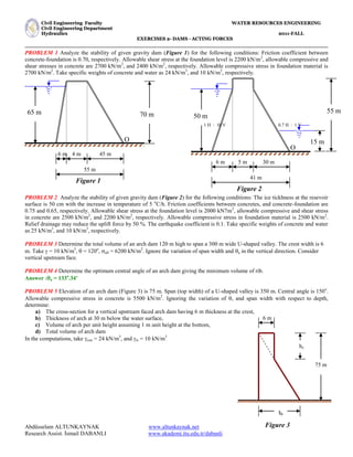
  • 1. C Ci iv vi il l E En ng gi in ne ee er ri in ng g F Fa ac cu ul lt ty y W WA AT TE ER R R RE ES SO OU UR RC CE ES S E EN NG GI IN NE EE ER RI IN NG G C Ci iv vi il l E En ng gi in ne ee er ri in ng g D De ep pa ar rt tm me en nt t H Hy yd dr ra au ul li ic cs s 2 20 01 11 1- -F FA AL LL L E EX XE ER RC CI IS SE ES S 2 2- - D DA AM MS S - - A AC CT TI IN NG G F FO OR RC CE ES S Abdüsselam ALTUNKAYNAK www.altunkaynak.net Research Assist. İsmail DABANLI www.akademi.itu.edu.tr/dabanli PROBLEM 1 Analyze the stability of given gravity dam (Figure 1) for the following conditions: Friction coefficient between concrete-foundation is 0.70, respectively. Allowable shear stress at the foundation level is 2200 kN/m2 , allowable compressive and shear stresses in concrete are 2700 kN/m2 , and 2400 kN/m2 , respectively. Allowable compressive stress in foundation material is 2700 kN/m2 . Take specific weights of concrete and water as 24 kN/m3 , and 10 kN/m3 , respectively. PROBLEM 2 Analyze the stability of given gravity dam (Figure 2) for the following conditions: The ice tickhness at the resevoir surface is 50 cm with the increase in temperature of 5 o C/h. Friction coefficients between concretes, and concrete-foundation are 0.75 and 0.65, respectively. Allowable shear stress at the foundation level is 2000 kN7m2 , allowable compressive and shear stress in concrete are 2500 kN/m2 , and 2200 kN/m2 , respectively. Allowable compressive stress in foundation material is 2500 kN/m2 . Relief drainage may reduce the uplift force by 50 %. The earthquake coefficient is 0.1. Take specific weights of concrete and water as 25 kN/m3 , and 10 kN/m3 , respectively. PROBLEM 3 Determine the total volume of an arch dam 120 m high to span a 300 m wide U-shaped valley. The crest width is 6 m. Take  = 10 kN/m3 ,  = 120o , all = 6200 kN/m2 . Ignore the variation of span width and a in the vertical direction. Consider vertical upstream face. PROBLEM 4 Determine the optimum central angle of an arch dam giving the minimum volume of rib. Answer :a = 133o .34’ PROBLEM 5 Elevation of an arch dam (Figure 3) is 75 m. Span (top width) of a U-shaped valley is 350 m. Central angle is 150o . Allowable compressive stress in concrete is 5500 kN/m2 . Ignoring the variation of , and span width with respect to depth, determine: a) The cross-section for a vertical upstream faced arch dam having 6 m thickness at the crest, b) Thickness of arch at 30 m below the water surface, c) Volume of arch per unit height assuming 1 m unit height at the bottom, d) Total volume of arch dam In the computations, take con = 24 kN/m3 , and w = 10 kN/m3 hx 6 m tb 75 m 70 m 6 m 4 m 45 m 55 m O 65 m Figure 1 Figure 3 Figure 2 55 m 6 m 5 m 30 m 41 m O 50 m 0.7 H : 1 V 1 H : 10 V 15 m
  • 2. C Ci iv vi il l E En ng gi in ne ee er ri in ng g F Fa ac cu ul lt ty y W WA AT TE ER R R RE ES SO OU UR RC CE ES S E EN NG GI IN NE EE ER RI IN NG G C Ci iv vi il l E En ng gi in ne ee er ri in ng g D De ep pa ar rt tm me en nt t H Hy yd dr ra au ul li ic cs s 2 20 01 11 1- -F FA AL LL L E EX XE ER RC CI IS SE ES S 2 2- - D DA AM MS S - - A AC CT TI IN NG G F FO OR RC CE ES S Abdüsselam ALTUNKAYNAK www.altunkaynak.net Research Assist. İsmail DABANLI www.akademi.itu.edu.tr/dabanli SOLUTION 1  Forces and loads acting the dam: Fwh: Hydrostatic force produced by water in the reservoir and tail water in the downstream Fwv: Water load produced by water weight Fu : Uplift force produced by groundwater W : The weight of the dam (W1, W2, W3)  Free body diagram is shown in figure 4  The value of the forces, total vertical and total horizontal forces, and moments: W1 = 6 * ½ * 70 * 24 = 5040 kN XW1 = 1/3 * 6 + 4 + 45 = 51.00 m W1 * XW1 = 257040 kNm W2 = 4 * 70 * 24 = 6720 kN XW2 = ½ * 4 + 45 = 47.00 m W2 * XW2 =315840 kNm W3 = 45 * ½ * 70 * 24 = 37800 kN XW3 = 2/3 * 45 = 30.00 m W3 * XW3=1134000 kNm Fwv = 6 * ½ * 65 * 10 = 1950 kN Xwv = 2/3 * 6 + 4 + 45 = 53.00 m Fwv * XFv =103350 kNm Fwh = 65 * ½ * 65 * 10 = 21125 kN XFwh = 1/3 * 65 = 21.67 m Fwh * XFh =457779 kNm Fu = 65 * ½ * 55 * 10 = 17875 Kn XFu = 2/3 * 55 = 36.67 m Fu * XFu =655476 kNm  MO = 457779 + 655476 = 1113255 kNm/m  Mr = 257040 + 315840 + 1134000 + 103350 = 1810230 kNm/m  V = W1 + W2 + W3 + Fwv - Fu = 33635 kN/m  H = Fwh = 21125 kN/m FORCE (kN/m) MOMENT (kN/m/m) MOMENT ARM ABOUT O(m) 70 m 6 m 4 m 45 m 55 m O 65 m W1 W2 W3 Fwv Fwh Fu xm Figure 4
  • 3. C Ci iv vi il l E En ng gi in ne ee er ri in ng g F Fa ac cu ul lt ty y W WA AT TE ER R R RE ES SO OU UR RC CE ES S E EN NG GI IN NE EE ER RI IN NG G C Ci iv vi il l E En ng gi in ne ee er ri in ng g D De ep pa ar rt tm me en nt t H Hy yd dr ra au ul li ic cs s 2 20 01 11 1- -F FA AL LL L E EX XE ER RC CI IS SE ES S 2 2- - D DA AM MS S - - A AC CT TI IN NG G F FO OR RC CE ES S Abdüsselam ALTUNKAYNAK www.altunkaynak.net Research Assist. İsmail DABANLI www.akademi.itu.edu.tr/dabanli  Stability Check For the Whole Dam: 1. Overturning (F.S0): The dam must be safe against overturning for all loading conditions. F.S0 should be greater than 2.0 for usual loading, and than1.5 for unusual or severe loading. F.S0 =   O r M M = 1113255 1810230 = 1.626 > 1.5 O.K. 2. Sliding (F.SS): The dam must be safe against sliding over any horizontal plane. F.SS should be greater than 1.5 for usual loading and than 1.0 for unusual or severe loading. F.SS =    H V f = 21125 33635 7 . 0  = 1.11 > 1.0 O.K 3. Shear and sliding together (F.SSS): The dam must be also checked for shear and sliding together. F.SSS should be greater 5.0 for usual loading and 3.0 unusual and severe loading. F.SSS =       H A V f S  5 . 0 = 21125 2200 55 5 . 0 33635 7 . 0     = 3.98 > 3.0 O.K. 4. Stress (max/min): The contact stress between the foundation and the dam must be greater than zero and all points or the dam will be unsafe against overturning. Maximum base pressure (max) should be less than the allowable compressive stress and minimum base pressure (min) should be greater than zero.      V M M X O r = 33635 1113255 1810230  = 20.72 m e = 72 . 20 2 55  = 6.78 (eccentricity) M =  V * e = 33635 * 6.78 = 228045.3 kNm/m (the net moment about the centerline of the base) C = 2 55 = 27.5 m I = 12 1 553  = 13864.58 m3 ( the moment of interia) I C M B V     min max/  = 58 . 13864 5 . 27 3 . 228045 55 33635   max = 1063.87 kN/m2 < 2700 kN/m2 O.K. max = 159.22 kN/m2 > 0.00 kN/m2 O.K.
  • 4. C Ci iv vi il l E En ng gi in ne ee er ri in ng g F Fa ac cu ul lt ty y W WA AT TE ER R R RE ES SO OU UR RC CE ES S E EN NG GI IN NE EE ER RI IN NG G C Ci iv vi il l E En ng gi in ne ee er ri in ng g D De ep pa ar rt tm me en nt t H Hy yd dr ra au ul li ic cs s 2 20 01 11 1- -F FA AL LL L E EX XE ER RC CI IS SE ES S 2 2- - D DA AM MS S - - A AC CT TI IN NG G F FO OR RC CE ES S Abdüsselam ALTUNKAYNAK www.altunkaynak.net Research Assist. İsmail DABANLI www.akademi.itu.edu.tr/dabanli SOLUTION 2  Forces and loads acting the dam: Fi : Ice Load (for cold climates and Fi1, and Fi2 for reservoir and tail water in the downstream, respectively) Fw: Water force produced by earthquake (Fw1, and Fw2 for reservoir and tail water in the downstream, respectively) Fwh: Hydrostatic force produced by water in the reservoir and tail water in the downstream (Fwh1, and Fwh2) Fwv: Water load produced by water weight (Fwv1, and Fwv2 for reservoir and tail water in the downstream, respectively) Fu : Uplift force produced by groundwater (since the tail water in the downstream, the diagram of uplift force will be in trapezoidal shape) W : The weight of the dam (W1, W2, W3…Wn) Fd : Earthquake forces (Fdh1 and Fdv1: horizontally and vertically)  Free body diagram is shown in figure 4  Shear and sliding check due to ice force at the reservoir surface: Average shear stress: 5 90 = 18 kN/m2 << 2200 O.K. Sliding check: 90 25 5 5 75 . 0    = 5.21 >> 1.00 O.K. 55 m 6 m 5 m 30 m 41 m 50 m W1 W2 W3 Fwv1 Fwh1 Fu xm Fw1 Fi1 Fdv Fdh Figure 5 O 15 m Fwv2 Fwh2 Fw2 Fi2
  • 5. C Ci iv vi il l E En ng gi in ne ee er ri in ng g F Fa ac cu ul lt ty y W WA AT TE ER R R RE ES SO OU UR RC CE ES S E EN NG GI IN NE EE ER RI IN NG G C Ci iv vi il l E En ng gi in ne ee er ri in ng g D De ep pa ar rt tm me en nt t H Hy yd dr ra au ul li ic cs s 2 20 01 11 1- -F FA AL LL L E EX XE ER RC CI IS SE ES S 2 2- - D DA AM MS S - - A AC CT TI IN NG G F FO OR RC CE ES S Abdüsselam ALTUNKAYNAK www.altunkaynak.net Research Assist. İsmail DABANLI www.akademi.itu.edu.tr/dabanli  The value of the forces, total vertical and total horizontal forces, and moments: W1 = 50 * 6.0 * 0.5 *25 = 3750 kN 37.00 m 138750 kNm W2 = 55 * 5.0 * 1.0 *25 = 6875 kN 32.50 m 223438 kNm W3 = 50 * 30 * 0.5 * 25 = 18750 kN 20.00 m 375000 kNm Fwv1 = 50 * 6 * 0.5 * 10 = 1500 kN 39.00 m 58500 kNm Fwv2 = 15 * 9 * 0.5 * 10 = 675 kN 3.00 m 2025 kNm Fwh1 = 55 * 55 * 0.5*10 = 15125 kN 17.00 m 257125 kNm Fwh2 = 15 * 15 * 0.5*10 = 1125 kN 5.00 m 5625 kNm Fu =[(50+15)/2]*41*10*0.5= 6663 kN 23.30 m 168295 kNm FW1 = 0.726*C*k**h1 2 FW1 = 0.726*0.65*0.1*10*502 = 1180 kN 17.00 m 20056 kNm FW2 = 0.726*0.46*0.1*10*152 = 75 kN 5.00 m 375 kNm Fi1 = 90 kN 50.00 m 4500 kNm Fi2 = 90 kN 15.00 m 1350 kNm Fdv = k *W=0.1* 29375 =2937.5 kN 30.10 m 88419 kNm Fdh = k * W=0.1*29375 =2937.5 kN 20.64 m 60630 kNm  Stability Check For the Whole Dam (When vertical Fd (Fdv) is considered):  MO = 257125+168295+20056+4500+88419 = 538395 kNm/m  Mr = 138750+223438+375000+58500+2025+5625+375+1350 = 805063 kNm/m  V = W1 + W2 + W3 + Fwv1 + Fwv2- Fu -Fdv = 21950 kN/m  H = Fwh1- Fwh2 + FW1 - FW2 + Fi1 - Fi2 = 15105 kN/m 1. Overturning (F.S0): The dam must be safe against overturning for all loading conditions. F.S0 should be greater than 2.0 for usual loading, and than1.5 for unusual or severe loading. F.S0 =   O r M M = 538395 805063 = 1.495 < 1.5 NOT O.K. 2. Sliding (F.SS): The dam must be safe against sliding over any horizontal plane. F.SS should be greater than 1.5 for usual loading and than 1.0 for unusual or severe loading. F.SS =    H V f = 15105 21950 65 . 0  = 0.94 < 1.0 NOT O.K. FORCE (kN/m) MOMENT (kN/m/m) MOMENT ARM ABOUT O(m)
  • 6. C Ci iv vi il l E En ng gi in ne ee er ri in ng g F Fa ac cu ul lt ty y W WA AT TE ER R R RE ES SO OU UR RC CE ES S E EN NG GI IN NE EE ER RI IN NG G C Ci iv vi il l E En ng gi in ne ee er ri in ng g D De ep pa ar rt tm me en nt t H Hy yd dr ra au ul li ic cs s 2 20 01 11 1- -F FA AL LL L E EX XE ER RC CI IS SE ES S 2 2- - D DA AM MS S - - A AC CT TI IN NG G F FO OR RC CE ES S Abdüsselam ALTUNKAYNAK www.altunkaynak.net Research Assist. İsmail DABANLI www.akademi.itu.edu.tr/dabanli 3. Shear and sliding together (F.SSS): The dam must be also checked for shear and sliding together. F.SSS should be greater 5.0 for usual loading and 3.0 unusual and severe loading. F.SSS =       H A V f S  5 . 0 = 15105 2200 41 5 . 0 21950 65 . 0     = 3.93 > 3.0 O.K. 4. Stress (max/min): The contact stress between the foundation and the dam must be greater than zero and all points or the dam will be unsafe against overturning. Maximum base pressure (max) should be less than the allowable compressive stress and minimum base pressure (min) should be greater than zero.      V M M X O r = 21950 538395 805063  = 12.15 m e = 15 . 12 2 41  = 8.35 (eccentricity) M =  V * e = 21950 * 8.35 = 183307 kNm/m (the net moment about the centerline of the base) C = 2 41 = 20.5 m I = 12 1 413  = 5743.42 m4 ( the moment of interia) I C M B V     min max/  = 42 . 5743 5 . 20 183307 41 21950   max = 1189.64 kN/m2 < 2700 kN/m2 O.K. max = -118.91 kN/m2 < 0.00 kN/m2 NOT O.K.  Stability Check For the Whole Dam (When horizontal Fd (Fdh) is considered):  MO = 257125+168295+20056+4500+60630 = 510606.0 kNm/m  Mr = 138750+223438+375000+58500+2025+5625+375+1350 = 805063.0 kNm/m  V = W1 + W2 + W3 + Fwv1 + Fwv2 - Fu = 19012.5 kN/m  H = Fwh1- Fwh2 + FW1 - FW2 + Fi1 - Fi2 + Fdh = 18042.5 kN/m
  • 7. C Ci iv vi il l E En ng gi in ne ee er ri in ng g F Fa ac cu ul lt ty y W WA AT TE ER R R RE ES SO OU UR RC CE ES S E EN NG GI IN NE EE ER RI IN NG G C Ci iv vi il l E En ng gi in ne ee er ri in ng g D De ep pa ar rt tm me en nt t H Hy yd dr ra au ul li ic cs s 2 20 01 11 1- -F FA AL LL L E EX XE ER RC CI IS SE ES S 2 2- - D DA AM MS S - - A AC CT TI IN NG G F FO OR RC CE ES S Abdüsselam ALTUNKAYNAK www.altunkaynak.net Research Assist. İsmail DABANLI www.akademi.itu.edu.tr/dabanli 1. Overturning (F.S0): The dam must be safe against overturning for all loading conditions. F.S0 should be greater than 2.0 for usual loading, and than1.5 for unusual or severe loading. F.S0 =   O r M M = 510606 805063 = 1.58 > 1.5 O.K. 2. Sliding (F.SS): The dam must be safe against sliding over any horizontal plane. F.SS should be greater than 1.5 for usual loading and than 1.0 for unusual or severe loading. F.SS =    H V f = 5 . 18042 5 . 19012 65 . 0  = 0.65 < 1.0 NOT O.K. 3. Shear and sliding together (F.SSS): The dam must be also checked for shear and sliding together. F.SSS should be greater 5.0 for usual loading and 3.0 unusual and severe loading. F.SSS =       H A V f S  5 . 0 = 5 . 18042 2200 41 5 . 0 5 . 19012 65 . 0     = 3.19 > 3.0 O.K. 4. Stress (max/min): The contact stress between the foundation and the dam must be greater than zero and all points or the dam will be unsafe against overturning. Maximum base pressure (max) should be less than the allowable compressive stress and minimum base pressure (min) should be greater than zero.      V M M X O r = 5 . 19012 510606 805063  = 15.49 m e = 49 . 15 2 41  = 5.0 (eccentricity) M =  V * e = 19012.5 * 5.0 = 95299.25 kNm/m (the net moment about the centerline of the base) C = 2 41 = 20.5 m I = 12 1 413  = 5743.42 m4 ( the moment of interia) I C M B V     min max/  = 42 . 5743 5 . 20 25 . 95299 41 5 . 19012   max = 803.87 kN/m2 < 2700 kN/m2 O.K. max = 123.57 kN/m2 > 0.00 kN/m2 O.K.
  • 8. C Ci iv vi il l E En ng gi in ne ee er ri in ng g F Fa ac cu ul lt ty y W WA AT TE ER R R RE ES SO OU UR RC CE ES S E EN NG GI IN NE EE ER RI IN NG G C Ci iv vi il l E En ng gi in ne ee er ri in ng g D De ep pa ar rt tm me en nt t H Hy yd dr ra au ul li ic cs s 2 20 01 11 1- -F FA AL LL L E EX XE ER RC CI IS SE ES S 2 2- - D DA AM MS S - - A AC CT TI IN NG G F FO OR RC CE ES S Abdüsselam ALTUNKAYNAK www.altunkaynak.net Research Assist. İsmail DABANLI www.akademi.itu.edu.tr/dabanli SOLUTION 3 2 2  Sin B r   = 2 120 2 300 Sin  = 173 m Thickness at the base: tb = all r h     = 6200 173 120 10   = 33.5 m 173 10 6200 6     h = 21.5 m L = r *  = 120 180 173    = 362 m VT =   L h h t b h b b               2 =   362 5 . 21 120 2 5 . 33 6 5 . 21 6             = 750924 m3 SOLUTION 4 The optimum central angle  for a minimum volume of arch rib can be determined by differentiating the equation written below with respect to  and equating to zero. V =       all r h 2  V’ = Continue 120o 6 m 300 m 120o 6 m 300 m h*=21.5 m 6 m tb = 33.5 m 120 m Figure 6 Figure 7
  • 9. C Ci iv vi il l E En ng gi in ne ee er ri in ng g F Fa ac cu ul lt ty y W WA AT TE ER R R RE ES SO OU UR RC CE ES S E EN NG GI IN NE EE ER RI IN NG G C Ci iv vi il l E En ng gi in ne ee er ri in ng g D De ep pa ar rt tm me en nt t H Hy yd dr ra au ul li ic cs s 2 20 01 11 1- -F FA AL LL L E EX XE ER RC CI IS SE ES S 2 2- - D DA AM MS S - - A AC CT TI IN NG G F FO OR RC CE ES S Abdüsselam ALTUNKAYNAK www.altunkaynak.net Research Assist. İsmail DABANLI www.akademi.itu.edu.tr/dabanli SOLUTION 5 a) 2 2  Sin B r   = 2 150 2 350 Sin  = 181 m Thickness at the base: tb = all r h     = 5500 181 75 10   = 24.7 m 181 10 5500 6     h = 18.23 m b) t30 = 5500 181 30 10   = 9.87 m c) V =       all r h 2 = 150 180 5500 181 75 10 2      = 11695.65 m3 /m d) L = r *  = 150 180 181    = 474 m VT =   L h h t b h b b               2 =   474 23 . 18 75 2 7 . 24 6 23 . 18 6             = 464899 m3 hx=18.23 m 6 m tb=24.7 m 75 m Figure 8