
Recommended
Recommended
More Related Content
Similar to lec-02.pdf
Similar to lec-02.pdf (20)
Recently uploaded
Recently uploaded (20)
lec-02.pdf
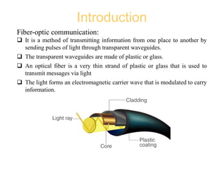
- 1. Introduction Fiber-optic communication: It is a method of transmitting information from one place to another by sending pulses of light through transparent waveguides. The transparent waveguides are made of plastic or glass. An optical fiber is a very thin strand of plastic or glass that is used to transmit messages via light The light forms an electromagnetic carrier wave that is modulated to carry information.
- 2. Introduction Why optical fiber is preferred : High bandwidth Long distance Immunity to electromagnetic interference required It can transmit voice, video, and telemetry through LAN, computer networks, or across long distances. Application of optical fiber: Medical: imaging tools, as laser for surgeries Defense/Government: Used as hydrophones for seismic waves and SONAR Data storage Telecommunications Networking Broadcast/CATV
- 3. Historical Development First generation (Graded-index fibers): Year implemented: 1980 Bit rate: 45 Mb/s Repeater spacing: 10 km Operating wavelength: 0.8 um Semiconductor: GaAs Second generation (Single-mode fibers): Year implemented: 1985 Bit rate: 100 Mb/s to 1.7 Gb/s Repeater spacing: 50 km Operating wavelength: 1.3 um Semiconductor: In GaAsP
- 4. Historical Development Third generation (Single-mode lasers): Year implemented: 1990 Bit rate: 10 Gb/s Repeater spacing: 100 km Operating wavelength: 1.55 um Fourth generation (Optical amplifiers): Year implemented: 1996 Bit rate: 10 Tb/s Repeater spacing: > 10,000 km Operating wavelength: 1.45 um to 1.62 um Fifth generation (Raman amplification): - Year implemented: 2002 - Bit rate: 40 Gb/s to 160 Gb/s - Repeater spacing: 24,000 km to 35,000 km - Operating wavelength: 1.53 um to 1.57 um
- 5. Progress in Lightwave Communication Technology
- 6. Transmission loss of silica fiber and optical communication wavelength bands
- 7. Electromagnetic spectrum & optical communication wavelength bands
- 8. General OFC System Basic block diagram of optical fiber communication system consists of following important blocks: Transmitter Information channel Receiver Optical fiber Message origin (Text/Video) Modulator Carrier Source Channel Coupler Message Output Processing Amplifier Optical Detector Repeater Information Channel Fig. Block diagram of OFC systems Transmitter Receiver
- 9. General OFC System Message origin: It is transducer convert non-electrical message to electrical signal. e.g., microphone, video camera Modulator: It converts the electrical message into proper format. It impresses this signal onto the wave generated by the carrier source. Two distinct categories of modulation are used i.e. analog modulation and digital modulation. Carrier source: Carrier source generates the wave on which the information is transmitted For fiber optic system, a laser diode (LD) or a light emitting diode (LED) is used.
- 10. General OFC System Channel coupler: Coupler feeds the power into the information channel Generally, lens are used as a channel coupler. The lens collimates the light emitted by the source and directing this light towards the receiver through fiber. Information channel: The information channel is the path between the transmitter and receiver. A glass or plastic fiber is used as a information channel. The channel attenuation should be low and large light acceptance angle. Repeater are used to regenerate weak and distorted signal. Another property of channel is propagation time. The signal in a channel contains different optic frequencies and divide its power along several ray paths, that cause pulse spreading.
- 11. General OFC System Optical detector: In the fiber system the optic wave is converted into an electric current by a photodetector. The important properties of photodetectors are small size, economy, long life, low power consumption, high sensitivity to optic signals and fast response to quick variations in the optic power. Signal processing: Signal processing includes filtering, amplification. Proper filtering maximizes the ratio of signal to unwanted power. For a digital system, the BER should be small. Message output: The electrical form of the message emerging from the signal processor is transformed into a sound wave or visual image. Sometimes these signals are directly usable when computers or other machines are connected through a fiber system.
- 12. Elements Source & Modulators LED, LD etc. Multiplexers & Demultiplexers WDM, DWDM etc. Amplifiers or Repeaters Connectors, Couplers, Isolators, etc. Detectors & Demodulators PD, APD, PIN etc. End Mile Networks 4/3/2022 12 Department of ICT, MBSTU
- 13. SEA-ME-WE 4/3/2022 13 South East Asia–Middle East–Western Europe 4 (SEA-ME-WE 4) is an optical fibre submarine communications cable system that carries telecommunications between Singapore, Malaysia, Thailand, Bangladesh, India, Sri Lanka, Pakistan, United Arab Emirates, Saudi Arabia, Sudan, Egypt, Italy, Tunisia, Algeria and France.[1] It is intended to be a complement to, rather than a replacement for, the SEA-ME-WE 3 cable. The cable is approximately 18,800 kilometres long, and provides the primary Internet backbone between South East Asia, the Indian subcontinent, the Middle East and Europe Department of ICT, MBSTU
- 14. Advantages of Optical Fiber Advantages of OFC: Extremely high bandwidth: Longer distance: Typically, it is less than 1dB/km. Immune to cross talk Resistance to electromagnetic interference Low security risk Small size Light weight Greater flexibility Easy accommodate increasing bandwidth
- 15. Disadvantages of Optical Fiber disadvantages of OFC: High initial cost Maintenance and repairing cost Jointing and test procedures Tensile stress Fiber losses