SlideShare a Scribd company logo
1 of 14
Download to read offline
BMS S05
High voltage stackable BMS system
Datasheet
Features
- Stackable design with one master and more slaves unit.
o Each unit controls 24 cells (divided into two 12 cells groups)
- High precision cell voltage measurement with 1.2 mV maximum total error
- External high precision digitally isolated shunt for current measurement
- Passive cell balancing (balancing current 0.5 A). Fully programmable balancing settings. Supports initial
pack balancing (requires charger with current control).
- Controls external charger
o Charger disconnect relay
o Charger current control (0-10 V or PWM) on selected chargers
- Battery protections:
o Under voltage
o Overvoltage (during charging and regeneration in discharge mode)
o Overcurrent
o Low and high temperature
- Battery monitoring functions
o Calculates SOC
o Measures cell internal resistance
o Reported cell voltages are open cell voltages (compensated for internal resistance).
o Calculates SOH (state of health). This is possible if battery fully discharged durring use.
o Measures total charge in battery life time
o Counts:
Number of cycles
Number of deep discharge events (SOC < 10%)
- Calculates maximum discharge and charge limits according to actual battery state
- BMS protections
o Broken string or cell connection
o Broken connection between stacked BMS modules
o Error on shunt (no communication, wrong value)
o Problem with internal BMS balancing resistors
o Each cell connection has internal fuse and overvoltage protection
o Over temperature protection for BMS. It will reduce charging current and number of active
balancing resistors in case of BMS overheating
o Watchdog for SW monitoring
o HW watchdog for monitoring balancing resistors and all relay outputs
- BMS indicators
o LED diode for each cell shows balancing function
o LED diode on each BMS shows communication from master to each of slave modules in BMS
stack
o Seven segment display
Shows current mode (Discharge, charge, final balancing error)
Shows current SOC, cell voltage difference in final balancing or error code
- Logging functions
o Fully customizable which values are logged
o Data is stored in internal FLASH
o Download with PC software, support for graphs and export to CSV text files.
- Auto installation
o BMS automatically detect connected cells at power on and verifies if total number of cells is equal
as configured
o In each group of 12 cells can be random connected (as long total voltage in each group is always
above 11 V).
- Hardware functions
o Integrated control for main battery relay and pre-charge relay
o Integrated high voltage isolation monitor
o Integrated high voltage interlock
o Analogue outputs or PWM for SOC, maximum charge and discharge current
o One temperature sensor for each group of 12 cells
o Control for external battery fan
o BMS aluminum back plate used for cooling
o Additional heat sink can be mounted on BMS back plate
- Communication interfaces:
o CAN interface (Canopen standard).
o Secondary CAN acts as OBD II master. Standard vehicle displays/gauges can be used. Support for
OBD scan applications (example Torque pro on tablets)
o RS232
Isolation
Cell connections with cell functionality (voltage, temperature measurement, balancing) are isolated from rest of
circuit. Isolation voltage 1000 Vdc.
DC/DC converter, isolation monitor and pre-charge detect circuit are isolated from rest of circuit. Isolation voltage
1000 Vdc.
Logic functions (communication, inputs, and outputs) have 60 V DC isolation from backplate.
BMS back plate is electrical isolated from rest of circuit. (1000 or 6 V DC).
Isolation monitor requires that BMS heatsink. Isolation monitors has internal 1 Mohm resistors from HV- and HV+
to logic GND.
Picture Isolation between BMS subsystems
Stacking of BMS
BMS can be stacked to support high voltage applications. Each module supports 24 cells. On one master module can
be connected up to 5 slave modules. Such configuration supports up to 144 cells in the series.
Picture: Stacking and current sensor
Master unit can be used as slave if connectors X3, X5, X6 are not connected. This is not price optimal, but allows
stacking of same battery blocks equipped with master modules.
Standard M8 cables are used for stacking. Each module is delivered with stacking cable so no additional cables are
needed. Standard length of stacking cable is 0.5 m, other length on request.
Current sensor
External current sensor /shunt can be connected to master module. It is fully isolated and powered from master
module.
Specification for current sensor
- maximum current 500 A
- accuracy 0.5 % (each sensor is calibrated)
- Offset error < 100 mA
- shunt resistance 0.1 mOhm
- digital isolated communication with BMS
Current sensor is supplied with 0.5 m long cable to BMS.
Connectors master module
X1
Current sensor/lower stack
M8 4 pin, codding A, female. Signals isolation from chasis 60 V.
1 GND
2 Com- BMS communication
3 Com+ BMS communication
4 5 V Used for power current sensor. Max 50 mA
Shield Connected to BMS heat sink with 1 MOhm
X2
Upper stack M8 cable
M8 4 pin, codding A, female. Signals isolation from chasis 60 V.
1
2 Com- BMS communication
3 Com+ BMS communication
4
Shield Connected to BMS heat sink with 1 MOhm
X3
Extra communication
Molex Mini-Fit 8 pin. Signals isolation from chasis 60 V.
1 GND
2 RS232 Tx
3 Rs232 Rx
4 Boot Used for SW upgrade. Connect to GND for upgrade
5 +Power For powering OBD II interfaces. Max 100 mA. Same voltage as on Power
source inputs on main connector.
6 GND
7 CAN2H Second CAN interface. Used as OBD II master
8 CAN2L
X4a, X4b
Cell connections
Molex Mini-Fit 16 pin. Isolation from chassis 800 VDC.
1 Temp. return
2 Temp. sensor 1 NTC 10 k B25/50 value of 3380K
3 Temp. sensor 2 NTC 10 k
4 Cell 1-
5 Cell 1+
6 Cell 2+
7 Cell 3+
8 Cell 4+
9 Cell 5+
10 Cell 6+
11 Cell 7+
12 Cell 8+
13 Cell 9+
14 Cell 10+
15 Cell 11+
16 Cell 12+
X5
System connector
Molex Mini-Fit 24 pin
Pin Name Full name Rating Comment
POWER SECTION
13 Pa Always On Power Source 8-30V (to CPU as
Analog IN)
1 Pd Ready Power Source (Discharge mode) Can be connected to
output of internal 12
DC/DC
8-30V (to CPU as
Analog IN)
2 Pc Charge Power Source Connected to
charger auxiliary
12V
8-30V (to CPU as
Analog IN)
14 GND GND
18 I01 Multi purpose input or low side out Max. 30V (to CPU as
Analog IN) . Pull
down 10k. Output can
be also PWM. Max
current 200mA.
Suppressor 33 V
placed across the line
(ZXMS6004)
19 I02 Multi purpose input or low side out See IO1. Different
timer for PWM.
Analog input range 0-5
V
OUTPUTS
11 O2 Main DC contactor positive
OUT2
Switch to GND
max 4 A
23 O3 Main DC contactor negative
OUT3
Switch to GND
max 4A
8 O4 Pre-charge contactor
OUT4
Switch to GND
max 1A
9 O5 Charge Allowed
OUT5
Switch to GND
max 1A
Signal that battery can
absorb energy. Used to
prevent controller
regeneration
10 O6 Charger Enable Switch to GND Controls charger relay
OUT6 max 1A
20 O7 OUT7 Switch to GND
max 1A
21 O8 OUT8 Switch to GND
max 1A
22 O9 PWM output
OUT9
To CPU timer
max 200 mA
Open collector out.
Internal pull up (4,7k)
with diode to logic
power (Diodes
ZXMS6004FF).
Active low
Suppressor 33 V
placed across the line
ANALOGUE OUTPUTS
15 As SOC state analogue out linear 0-5V,
max 20 mA
4 Ac Max. Charger current DAC/PWM linear 0-5V or PWM
mode, max 20 mA
3 Ad Max. Discharge current DAC/PWM linear 0-5V or PWM
mode, max 20 mA
16 GND GND
CAN
6 Ch CAN1H
5 Cl CAN1L
17 GNDc GND (optional isolated)
INTERLOCK
7 Lck HV Interlock + Internal hardware
voltage comparator.
Open all relays on
fault.
10 mA current source
from logic power.
Nominal voltage 2.5
V. Nominal external
resistor 220 Ohms to
GND
Connector pinout
1 2 3 4 5 6 7 8 9 10 11 12
Pd Pc Ad Ac Cl Ch Lck O4 O5 O6 O2 GND
Pa GND As GND GNDc IO1 IO2 O7 O8 O9 O3 GND
13 14 15 16 17 18 19 20 21 22 23 24
X6
Molex Mini-Fit 5 pin single row
High voltage connector
1 HV - Direct connection to stack -
.
Used in isolation fault
circuit.
Internally connected with 1
MOhm to BMS heat sink
2
3 Pre-charge sense Measures difference
between HV+ and this pin to
detect when pre-charging is
finished
4
5 HV+ Direct connection to stack
+.
Used in isolation fault
circuit.
Internally connected with 1
MOhm to BMS heat sink
X7
Discharge relay
Molex Mini-Fit 3 pin single rowi
1 Discharge Enable relay - See description of Discharge
Enable +
2
3 Discharge Enable relay +
OUT1
Internal electronic DC
relay 400 V 2A. 1kV
isolation from rest of
circuit. Suppressor 500 V
across contacts
If discharge is allowed
is activated before/after
precharge phase.
LED diodes
On slave module (per 12 cell block):
1x yellow – blink with 1 Hz on communication with balancer IC
8x green – connected with balancing resistor
On master PCB:
- Green and Red for Canopen functionality
- Blue – Bluetooth
- Yellow – CAN2
- Yellow – RS232
Connectors slave module
Slave module has only cells (X4a, X4b) and stack (X1, X2) connectors.
Dimensions
Dimensions with optional 40 mm high heat sink.

More Related Content

What's hot

Advanced motion controls azbh20a8
Advanced motion controls azbh20a8Advanced motion controls azbh20a8
Advanced motion controls azbh20a8Electromate
 
Original IGBT 6MBP20XSF060-50 20XSF060 060 20A 600V New Fuji
Original IGBT 6MBP20XSF060-50 20XSF060 060 20A 600V New FujiOriginal IGBT 6MBP20XSF060-50 20XSF060 060 20A 600V New Fuji
Original IGBT 6MBP20XSF060-50 20XSF060 060 20A 600V New FujiAUTHELECTRONIC
 
EC/Bios Interaction Laptop Repair Course
EC/Bios Interaction Laptop Repair CourseEC/Bios Interaction Laptop Repair Course
EC/Bios Interaction Laptop Repair CourseVikas Deoarshi
 
Amplificadores transistorizados multietapa
Amplificadores transistorizados multietapaAmplificadores transistorizados multietapa
Amplificadores transistorizados multietapaDavidDuarte573621
 
Iec symbol reference
Iec symbol referenceIec symbol reference
Iec symbol referenceVamsi Krishna
 
Original Power Supply IC TNY266PN TNY266P TNY266 DIP-7 New
Original Power Supply IC TNY266PN TNY266P TNY266 DIP-7 NewOriginal Power Supply IC TNY266PN TNY266P TNY266 DIP-7 New
Original Power Supply IC TNY266PN TNY266P TNY266 DIP-7 NewAUTHELECTRONIC
 
Components 555 timer
Components   555 timerComponents   555 timer
Components 555 timersld1950
 
Min bec pb5004
Min bec pb5004Min bec pb5004
Min bec pb5004sdshobby
 
Datasheet-emdrive150
Datasheet-emdrive150Datasheet-emdrive150
Datasheet-emdrive150Martin Pec
 
Components transistors
Components   transistorsComponents   transistors
Components transistorssld1950
 
Data sheet en_us_1889010827
Data sheet en_us_1889010827Data sheet en_us_1889010827
Data sheet en_us_1889010827amthanhbosch
 
Datasheet-emdriveH300
Datasheet-emdriveH300Datasheet-emdriveH300
Datasheet-emdriveH300Martin Pec
 
Epi laboratorio-citro-b-chura huillca isaac gustavo-8
Epi laboratorio-citro-b-chura huillca isaac gustavo-8Epi laboratorio-citro-b-chura huillca isaac gustavo-8
Epi laboratorio-citro-b-chura huillca isaac gustavo-8SteepHache
 
Amplificador tda7057 aq
Amplificador tda7057 aqAmplificador tda7057 aq
Amplificador tda7057 aqAntonio Gil
 

What's hot (20)

Advanced motion controls azbh20a8
Advanced motion controls azbh20a8Advanced motion controls azbh20a8
Advanced motion controls azbh20a8
 
Original IGBT 6MBP20XSF060-50 20XSF060 060 20A 600V New Fuji
Original IGBT 6MBP20XSF060-50 20XSF060 060 20A 600V New FujiOriginal IGBT 6MBP20XSF060-50 20XSF060 060 20A 600V New Fuji
Original IGBT 6MBP20XSF060-50 20XSF060 060 20A 600V New Fuji
 
EC/Bios Interaction Laptop Repair Course
EC/Bios Interaction Laptop Repair CourseEC/Bios Interaction Laptop Repair Course
EC/Bios Interaction Laptop Repair Course
 
Amplificadores transistorizados multietapa
Amplificadores transistorizados multietapaAmplificadores transistorizados multietapa
Amplificadores transistorizados multietapa
 
Iec symbol reference
Iec symbol referenceIec symbol reference
Iec symbol reference
 
Original Power Supply IC TNY266PN TNY266P TNY266 DIP-7 New
Original Power Supply IC TNY266PN TNY266P TNY266 DIP-7 NewOriginal Power Supply IC TNY266PN TNY266P TNY266 DIP-7 New
Original Power Supply IC TNY266PN TNY266P TNY266 DIP-7 New
 
Igbt reliability
Igbt reliabilityIgbt reliability
Igbt reliability
 
Components 555 timer
Components   555 timerComponents   555 timer
Components 555 timer
 
Min bec pb5004
Min bec pb5004Min bec pb5004
Min bec pb5004
 
Tm035 hdht
Tm035 hdhtTm035 hdht
Tm035 hdht
 
Datasheet-emdrive150
Datasheet-emdrive150Datasheet-emdrive150
Datasheet-emdrive150
 
Components transistors
Components   transistorsComponents   transistors
Components transistors
 
Digital dice
Digital diceDigital dice
Digital dice
 
Data sheet en_us_1889010827
Data sheet en_us_1889010827Data sheet en_us_1889010827
Data sheet en_us_1889010827
 
File 5e8ed4ef42f92
File 5e8ed4ef42f92File 5e8ed4ef42f92
File 5e8ed4ef42f92
 
Datasheet-emdriveH300
Datasheet-emdriveH300Datasheet-emdriveH300
Datasheet-emdriveH300
 
000746
000746000746
000746
 
Tda8511 j
Tda8511 jTda8511 j
Tda8511 j
 
Epi laboratorio-citro-b-chura huillca isaac gustavo-8
Epi laboratorio-citro-b-chura huillca isaac gustavo-8Epi laboratorio-citro-b-chura huillca isaac gustavo-8
Epi laboratorio-citro-b-chura huillca isaac gustavo-8
 
Amplificador tda7057 aq
Amplificador tda7057 aqAmplificador tda7057 aq
Amplificador tda7057 aq
 

Viewers also liked

Caching portfolio of JCP-Connect
Caching portfolio of JCP-ConnectCaching portfolio of JCP-Connect
Caching portfolio of JCP-ConnectJean-Charles Point
 
Dünya yazarları derlemesi
Dünya yazarları derlemesiDünya yazarları derlemesi
Dünya yazarları derlemesiMesut Mert
 
AACI Newsletter Issue 1 PRINT
AACI Newsletter Issue 1 PRINTAACI Newsletter Issue 1 PRINT
AACI Newsletter Issue 1 PRINTNam Le
 
Daño del cobre al ambiente
Daño del cobre al ambienteDaño del cobre al ambiente
Daño del cobre al ambienteYan Martinez
 
Shivani pawar resume
Shivani pawar resumeShivani pawar resume
Shivani pawar resumeshivani pawar
 
Prezentacja dla inwestorow_styczen_2013
Prezentacja dla inwestorow_styczen_2013Prezentacja dla inwestorow_styczen_2013
Prezentacja dla inwestorow_styczen_2013marekkosma12345
 
Who's up nxt at branded content event
Who's up nxt at branded content eventWho's up nxt at branded content event
Who's up nxt at branded content eventHeidi Bouhuijzen
 
Insite Software and Geriatric Medical at IRCE 2016: Does eCommerce Self-Servi...
Insite Software and Geriatric Medical at IRCE 2016: Does eCommerce Self-Servi...Insite Software and Geriatric Medical at IRCE 2016: Does eCommerce Self-Servi...
Insite Software and Geriatric Medical at IRCE 2016: Does eCommerce Self-Servi...Celia Ridley
 
Batiste Power Point Presentation for First Steps
Batiste Power Point Presentation for First StepsBatiste Power Point Presentation for First Steps
Batiste Power Point Presentation for First StepsRebecca Holland
 
Cloud Computing vs Virtualization From Desktop to Server
Cloud Computing vs Virtualization From Desktop to ServerCloud Computing vs Virtualization From Desktop to Server
Cloud Computing vs Virtualization From Desktop to ServerFadly Rizal Ahmad Fadzil
 

Viewers also liked (20)

sasiresume
sasiresumesasiresume
sasiresume
 
Présentation organisation natagriwal asbl
Présentation organisation natagriwal asblPrésentation organisation natagriwal asbl
Présentation organisation natagriwal asbl
 
Caching portfolio of JCP-Connect
Caching portfolio of JCP-ConnectCaching portfolio of JCP-Connect
Caching portfolio of JCP-Connect
 
Dünya yazarları derlemesi
Dünya yazarları derlemesiDünya yazarları derlemesi
Dünya yazarları derlemesi
 
AACI Newsletter Issue 1 PRINT
AACI Newsletter Issue 1 PRINTAACI Newsletter Issue 1 PRINT
AACI Newsletter Issue 1 PRINT
 
Daño del cobre al ambiente
Daño del cobre al ambienteDaño del cobre al ambiente
Daño del cobre al ambiente
 
Shivani pawar resume
Shivani pawar resumeShivani pawar resume
Shivani pawar resume
 
Les actions de la province de liège
Les actions de la province de liègeLes actions de la province de liège
Les actions de la province de liège
 
Robert van den Ham VI
Robert van den Ham VIRobert van den Ham VI
Robert van den Ham VI
 
Prezentacja dla inwestorow_styczen_2013
Prezentacja dla inwestorow_styczen_2013Prezentacja dla inwestorow_styczen_2013
Prezentacja dla inwestorow_styczen_2013
 
Puck Landee Wehkamp
Puck Landee WehkampPuck Landee Wehkamp
Puck Landee Wehkamp
 
Who's up nxt at branded content event
Who's up nxt at branded content eventWho's up nxt at branded content event
Who's up nxt at branded content event
 
Kubja Nagar
Kubja NagarKubja Nagar
Kubja Nagar
 
Insite Software and Geriatric Medical at IRCE 2016: Does eCommerce Self-Servi...
Insite Software and Geriatric Medical at IRCE 2016: Does eCommerce Self-Servi...Insite Software and Geriatric Medical at IRCE 2016: Does eCommerce Self-Servi...
Insite Software and Geriatric Medical at IRCE 2016: Does eCommerce Self-Servi...
 
Instalación de Software
Instalación de SoftwareInstalación de Software
Instalación de Software
 
Colter's Creek Winery Campaign
Colter's Creek Winery CampaignColter's Creek Winery Campaign
Colter's Creek Winery Campaign
 
Batiste Power Point Presentation for First Steps
Batiste Power Point Presentation for First StepsBatiste Power Point Presentation for First Steps
Batiste Power Point Presentation for First Steps
 
Cloud Computing vs Virtualization From Desktop to Server
Cloud Computing vs Virtualization From Desktop to ServerCloud Computing vs Virtualization From Desktop to Server
Cloud Computing vs Virtualization From Desktop to Server
 
Task 2
Task 2Task 2
Task 2
 
Kubja Nagar
Kubja NagarKubja Nagar
Kubja Nagar
 

Similar to Datasheet-bmss05

Three cell battery manager module
Three cell battery manager moduleThree cell battery manager module
Three cell battery manager modulelouayalhomsi
 
Speed Control of DC motor using AT89C52 IC
Speed Control of DC motor using AT89C52 ICSpeed Control of DC motor using AT89C52 IC
Speed Control of DC motor using AT89C52 ICDisha Modi
 
Cockpit White Box
Cockpit White BoxCockpit White Box
Cockpit White Boxncct
 
K48 Controller
K48 ControllerK48 Controller
K48 ControllerJoseph
 
LPD8803/LPD8806 Datasheet
LPD8803/LPD8806 DatasheetLPD8803/LPD8806 Datasheet
LPD8803/LPD8806 Datasheetlightingnext
 
K49 Controller
K49 ControllerK49 Controller
K49 ControllerJoseph
 
LTC6420 - Dual Matched 1.8GHz Differential Amplifiers / ADC Drivers
LTC6420 - Dual Matched 1.8GHz Differential Amplifiers / ADC DriversLTC6420 - Dual Matched 1.8GHz Differential Amplifiers / ADC Drivers
LTC6420 - Dual Matched 1.8GHz Differential Amplifiers / ADC DriversPremier Farnell
 
SDC 602RF Data Sheet
SDC 602RF Data SheetSDC 602RF Data Sheet
SDC 602RF Data SheetJMAC Supply
 
power grid synchronization failure detection
power grid synchronization failure detectionpower grid synchronization failure detection
power grid synchronization failure detectionJay Hind
 
Original Power Supply IC LNK616PG LNK616P LNK616 DIP-7 New
Original Power Supply IC LNK616PG LNK616P LNK616 DIP-7 NewOriginal Power Supply IC LNK616PG LNK616P LNK616 DIP-7 New
Original Power Supply IC LNK616PG LNK616P LNK616 DIP-7 NewAUTHELECTRONIC
 
Advanced motion controls azbh60a8
Advanced motion controls azbh60a8Advanced motion controls azbh60a8
Advanced motion controls azbh60a8Electromate
 
Advanced motion controls azbh6a8
Advanced motion controls azbh6a8Advanced motion controls azbh6a8
Advanced motion controls azbh6a8Electromate
 
Power sources complete
Power sources completePower sources complete
Power sources completeAnand Kumar
 
K31 Controller
K31 ControllerK31 Controller
K31 ControllerJoseph
 
Voltage & frequency monitoring through lcd
Voltage & frequency monitoring through lcdVoltage & frequency monitoring through lcd
Voltage & frequency monitoring through lcdHariKishore Karanapu
 
Advanced motion controls azbe12a8
Advanced motion controls azbe12a8Advanced motion controls azbe12a8
Advanced motion controls azbe12a8Electromate
 

Similar to Datasheet-bmss05 (20)

Three cell battery manager module
Three cell battery manager moduleThree cell battery manager module
Three cell battery manager module
 
Speed control of motor
Speed control of motorSpeed control of motor
Speed control of motor
 
Speed Control of DC motor using AT89C52 IC
Speed Control of DC motor using AT89C52 ICSpeed Control of DC motor using AT89C52 IC
Speed Control of DC motor using AT89C52 IC
 
Cockpit White Box
Cockpit White BoxCockpit White Box
Cockpit White Box
 
K48 Controller
K48 ControllerK48 Controller
K48 Controller
 
Acs712 datasheet
Acs712 datasheetAcs712 datasheet
Acs712 datasheet
 
TOP412GN.pdf
TOP412GN.pdfTOP412GN.pdf
TOP412GN.pdf
 
LPD8803/LPD8806 Datasheet
LPD8803/LPD8806 DatasheetLPD8803/LPD8806 Datasheet
LPD8803/LPD8806 Datasheet
 
K49 Controller
K49 ControllerK49 Controller
K49 Controller
 
LTC6420 - Dual Matched 1.8GHz Differential Amplifiers / ADC Drivers
LTC6420 - Dual Matched 1.8GHz Differential Amplifiers / ADC DriversLTC6420 - Dual Matched 1.8GHz Differential Amplifiers / ADC Drivers
LTC6420 - Dual Matched 1.8GHz Differential Amplifiers / ADC Drivers
 
SDC 602RF Data Sheet
SDC 602RF Data SheetSDC 602RF Data Sheet
SDC 602RF Data Sheet
 
power grid synchronization failure detection
power grid synchronization failure detectionpower grid synchronization failure detection
power grid synchronization failure detection
 
Original Power Supply IC LNK616PG LNK616P LNK616 DIP-7 New
Original Power Supply IC LNK616PG LNK616P LNK616 DIP-7 NewOriginal Power Supply IC LNK616PG LNK616P LNK616 DIP-7 New
Original Power Supply IC LNK616PG LNK616P LNK616 DIP-7 New
 
Automatic irrigation system
Automatic irrigation systemAutomatic irrigation system
Automatic irrigation system
 
Advanced motion controls azbh60a8
Advanced motion controls azbh60a8Advanced motion controls azbh60a8
Advanced motion controls azbh60a8
 
Advanced motion controls azbh6a8
Advanced motion controls azbh6a8Advanced motion controls azbh6a8
Advanced motion controls azbh6a8
 
Power sources complete
Power sources completePower sources complete
Power sources complete
 
K31 Controller
K31 ControllerK31 Controller
K31 Controller
 
Voltage & frequency monitoring through lcd
Voltage & frequency monitoring through lcdVoltage & frequency monitoring through lcd
Voltage & frequency monitoring through lcd
 
Advanced motion controls azbe12a8
Advanced motion controls azbe12a8Advanced motion controls azbe12a8
Advanced motion controls azbe12a8
 

Datasheet-bmss05

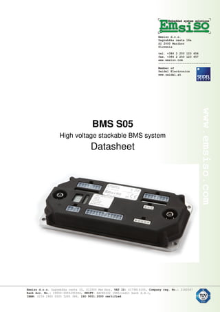
  • 1. BMS S05 High voltage stackable BMS system Datasheet
  • 2. Features - Stackable design with one master and more slaves unit. o Each unit controls 24 cells (divided into two 12 cells groups) - High precision cell voltage measurement with 1.2 mV maximum total error - External high precision digitally isolated shunt for current measurement - Passive cell balancing (balancing current 0.5 A). Fully programmable balancing settings. Supports initial pack balancing (requires charger with current control). - Controls external charger o Charger disconnect relay o Charger current control (0-10 V or PWM) on selected chargers - Battery protections: o Under voltage o Overvoltage (during charging and regeneration in discharge mode) o Overcurrent o Low and high temperature - Battery monitoring functions o Calculates SOC o Measures cell internal resistance o Reported cell voltages are open cell voltages (compensated for internal resistance). o Calculates SOH (state of health). This is possible if battery fully discharged durring use. o Measures total charge in battery life time o Counts: Number of cycles Number of deep discharge events (SOC < 10%) - Calculates maximum discharge and charge limits according to actual battery state - BMS protections o Broken string or cell connection o Broken connection between stacked BMS modules o Error on shunt (no communication, wrong value) o Problem with internal BMS balancing resistors o Each cell connection has internal fuse and overvoltage protection o Over temperature protection for BMS. It will reduce charging current and number of active balancing resistors in case of BMS overheating o Watchdog for SW monitoring o HW watchdog for monitoring balancing resistors and all relay outputs - BMS indicators o LED diode for each cell shows balancing function o LED diode on each BMS shows communication from master to each of slave modules in BMS stack o Seven segment display Shows current mode (Discharge, charge, final balancing error) Shows current SOC, cell voltage difference in final balancing or error code - Logging functions o Fully customizable which values are logged o Data is stored in internal FLASH o Download with PC software, support for graphs and export to CSV text files. - Auto installation o BMS automatically detect connected cells at power on and verifies if total number of cells is equal as configured
  • 3. o In each group of 12 cells can be random connected (as long total voltage in each group is always above 11 V). - Hardware functions o Integrated control for main battery relay and pre-charge relay o Integrated high voltage isolation monitor o Integrated high voltage interlock o Analogue outputs or PWM for SOC, maximum charge and discharge current o One temperature sensor for each group of 12 cells o Control for external battery fan o BMS aluminum back plate used for cooling o Additional heat sink can be mounted on BMS back plate - Communication interfaces: o CAN interface (Canopen standard). o Secondary CAN acts as OBD II master. Standard vehicle displays/gauges can be used. Support for OBD scan applications (example Torque pro on tablets) o RS232 Isolation Cell connections with cell functionality (voltage, temperature measurement, balancing) are isolated from rest of circuit. Isolation voltage 1000 Vdc. DC/DC converter, isolation monitor and pre-charge detect circuit are isolated from rest of circuit. Isolation voltage 1000 Vdc. Logic functions (communication, inputs, and outputs) have 60 V DC isolation from backplate. BMS back plate is electrical isolated from rest of circuit. (1000 or 6 V DC). Isolation monitor requires that BMS heatsink. Isolation monitors has internal 1 Mohm resistors from HV- and HV+ to logic GND.
  • 4. Picture Isolation between BMS subsystems
  • 5. Stacking of BMS BMS can be stacked to support high voltage applications. Each module supports 24 cells. On one master module can be connected up to 5 slave modules. Such configuration supports up to 144 cells in the series. Picture: Stacking and current sensor Master unit can be used as slave if connectors X3, X5, X6 are not connected. This is not price optimal, but allows stacking of same battery blocks equipped with master modules. Standard M8 cables are used for stacking. Each module is delivered with stacking cable so no additional cables are needed. Standard length of stacking cable is 0.5 m, other length on request.
  • 6. Current sensor External current sensor /shunt can be connected to master module. It is fully isolated and powered from master module. Specification for current sensor - maximum current 500 A - accuracy 0.5 % (each sensor is calibrated) - Offset error < 100 mA - shunt resistance 0.1 mOhm - digital isolated communication with BMS Current sensor is supplied with 0.5 m long cable to BMS.
  • 7. Connectors master module X1 Current sensor/lower stack M8 4 pin, codding A, female. Signals isolation from chasis 60 V. 1 GND 2 Com- BMS communication 3 Com+ BMS communication 4 5 V Used for power current sensor. Max 50 mA Shield Connected to BMS heat sink with 1 MOhm
  • 8. X2 Upper stack M8 cable M8 4 pin, codding A, female. Signals isolation from chasis 60 V. 1 2 Com- BMS communication 3 Com+ BMS communication 4 Shield Connected to BMS heat sink with 1 MOhm X3 Extra communication Molex Mini-Fit 8 pin. Signals isolation from chasis 60 V. 1 GND 2 RS232 Tx 3 Rs232 Rx 4 Boot Used for SW upgrade. Connect to GND for upgrade 5 +Power For powering OBD II interfaces. Max 100 mA. Same voltage as on Power source inputs on main connector. 6 GND 7 CAN2H Second CAN interface. Used as OBD II master 8 CAN2L
  • 9. X4a, X4b Cell connections Molex Mini-Fit 16 pin. Isolation from chassis 800 VDC. 1 Temp. return 2 Temp. sensor 1 NTC 10 k B25/50 value of 3380K 3 Temp. sensor 2 NTC 10 k 4 Cell 1- 5 Cell 1+ 6 Cell 2+ 7 Cell 3+ 8 Cell 4+ 9 Cell 5+ 10 Cell 6+ 11 Cell 7+ 12 Cell 8+ 13 Cell 9+ 14 Cell 10+ 15 Cell 11+ 16 Cell 12+
  • 10. X5 System connector Molex Mini-Fit 24 pin Pin Name Full name Rating Comment POWER SECTION 13 Pa Always On Power Source 8-30V (to CPU as Analog IN) 1 Pd Ready Power Source (Discharge mode) Can be connected to output of internal 12 DC/DC 8-30V (to CPU as Analog IN) 2 Pc Charge Power Source Connected to charger auxiliary 12V 8-30V (to CPU as Analog IN) 14 GND GND 18 I01 Multi purpose input or low side out Max. 30V (to CPU as Analog IN) . Pull down 10k. Output can be also PWM. Max current 200mA. Suppressor 33 V placed across the line (ZXMS6004) 19 I02 Multi purpose input or low side out See IO1. Different timer for PWM. Analog input range 0-5 V OUTPUTS 11 O2 Main DC contactor positive OUT2 Switch to GND max 4 A 23 O3 Main DC contactor negative OUT3 Switch to GND max 4A 8 O4 Pre-charge contactor OUT4 Switch to GND max 1A 9 O5 Charge Allowed OUT5 Switch to GND max 1A Signal that battery can absorb energy. Used to prevent controller regeneration 10 O6 Charger Enable Switch to GND Controls charger relay
  • 11. OUT6 max 1A 20 O7 OUT7 Switch to GND max 1A 21 O8 OUT8 Switch to GND max 1A 22 O9 PWM output OUT9 To CPU timer max 200 mA Open collector out. Internal pull up (4,7k) with diode to logic power (Diodes ZXMS6004FF). Active low Suppressor 33 V placed across the line ANALOGUE OUTPUTS 15 As SOC state analogue out linear 0-5V, max 20 mA 4 Ac Max. Charger current DAC/PWM linear 0-5V or PWM mode, max 20 mA 3 Ad Max. Discharge current DAC/PWM linear 0-5V or PWM mode, max 20 mA 16 GND GND CAN 6 Ch CAN1H 5 Cl CAN1L 17 GNDc GND (optional isolated) INTERLOCK 7 Lck HV Interlock + Internal hardware voltage comparator. Open all relays on fault. 10 mA current source from logic power. Nominal voltage 2.5 V. Nominal external resistor 220 Ohms to GND Connector pinout 1 2 3 4 5 6 7 8 9 10 11 12 Pd Pc Ad Ac Cl Ch Lck O4 O5 O6 O2 GND Pa GND As GND GNDc IO1 IO2 O7 O8 O9 O3 GND 13 14 15 16 17 18 19 20 21 22 23 24
  • 12. X6 Molex Mini-Fit 5 pin single row High voltage connector 1 HV - Direct connection to stack - . Used in isolation fault circuit. Internally connected with 1 MOhm to BMS heat sink 2 3 Pre-charge sense Measures difference between HV+ and this pin to detect when pre-charging is finished 4 5 HV+ Direct connection to stack +. Used in isolation fault circuit. Internally connected with 1 MOhm to BMS heat sink X7 Discharge relay Molex Mini-Fit 3 pin single rowi 1 Discharge Enable relay - See description of Discharge Enable + 2 3 Discharge Enable relay + OUT1 Internal electronic DC relay 400 V 2A. 1kV isolation from rest of circuit. Suppressor 500 V across contacts If discharge is allowed is activated before/after precharge phase.
  • 13. LED diodes On slave module (per 12 cell block): 1x yellow – blink with 1 Hz on communication with balancer IC 8x green – connected with balancing resistor On master PCB: - Green and Red for Canopen functionality - Blue – Bluetooth - Yellow – CAN2 - Yellow – RS232
  • 14. Connectors slave module Slave module has only cells (X4a, X4b) and stack (X1, X2) connectors. Dimensions Dimensions with optional 40 mm high heat sink.