1. Research
Focus
Area
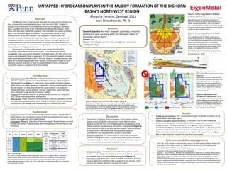
Figure 2: Research Focus Area within BighornBasin, Wyoming
Township and Range designations are overlain onto the geography of the Bighorn
Basin (outlinedin red). Note how Laramideuplifts (grey, Precambrianrocks)
surround the Basin, which has produced many oil and gas fields from Cretaceous
and Tertiary reservoirs. Thick blue line highlights study area. Grey dashed line
marks approximatetrace of Basin’s axial syncline. Adapted from Finn (2010).
UNTAPPED HYDROCARBON PLAYS IN THE MUDDY FORMATION OF THE BIGHORN
BASIN’S NORTHWEST REGION
Marjorie Ferrone, Geology, 2015
Jane Dmochowski, Ph. D.
Abstract
The Bighorn Basin of north-central Wyoming and south-central Montana has
been commercially producing hydrocarbons since the early 1900s. The Basin’s
geologic history generated a multitude of structural and stratigraphic petroleum
plays, including those found in the Thermopolis/Muddy/Mowry complex. While
these units have been repeatedly exploited, they most likely still contain profitable
plays in the northwest region of the Basin. This conclusion is based on the
fortuitous union of certain conditions, such as quality of hydrocarbon and
reservoir, formation thickness and depth, and degree and type of structural and
stratigraphic relation. Some of this information is drawn from well logs, but the
majority depends on previous interpretation of distinct and diverse researchers.
Conflicting explanations can create data incongruity, the meaning of which must be
interpreted, permitting operator error.
This research is a continuation of team work completed at the 2015
ExxonMobil Bighorn Basin Field School. Initially, it was decided that Muddy
stratigraphic traps could exist in the Basin’s northwest region, if it were not for the
unusual and undesirable facies arrangement. This influenced the team to conclude
that it would not be profitable to drill in the area. However, this determination was
based on limited and questionable data. I present further analysis based on more
extensive research that aims to more accurately define the facies changes and
assess their impact on the potential of future drilling.
Introduction
• Geographic Focus (Figure 2): Bighorn Basin’s Northwest Region, dimensions
defined as Wyoming’s Township 49 to 57 North and Range 100 to 103 West
• Stratigraphic Focus (Figure 1): Thermopolis Shale/ Muddy Sandstone/ Mowry
Shale; these units within the Basin’s stratigraphic column were chosen for study
for two reasons: (1) they demonstrate the classic features of a productive
stratigraphic trap: source, reservoir, and seal, respectively; and (2) the area
does not exhibit a high density of previous drilling
• Problem: All conditions required for productive hydrocarbon (HC) play were
met, except for proposed facies arrangement
• Why we care: Proper evaluation of an historically productive petroleum system
not only measures potential for future drilling in that area, but also contributes
to the cache of knowledge when approaching other potential drill sites
Summary
Research Question: Are there untapped, potentially productive
hydrocarbon plays remaining within the Northwest Region of
Wyoming’s Bighorn Basin?
Answer: Yes.
Reason: Paleo-facies are favorably arranged to constitute a
stratigraphic trap.
Figure 1: Stratigraphy
This chart is an approximation of the stratigraphiccolumn for the Bighorn Basin’s northwest
region. Relative width of rows is NOT indicativeof relativeunit thicknesses. A transgressive
period (sea level rise) occurred during deposition, indicatinga deepening of the Basin. Blue
outline highlights function of each unit of this study within a proposed petroleum play. Adapted
from Summa et al. (2015).
Background
• Structural: During the Late Cretaceous, the Laramide Orogeny shaped Western
North America into a borderland terrain of fault-bounded basins and uplifts, thus
forming the topography of the Bighorn Basin
• Stratigraphic (Figure 1): Deposition of the Thermopolis/ Muddy/ Mowry occurred
beneath the Western Interior Seaway, which transgressed from the Early to Late
Cretaceous
Discussion
• Depositional Conditions: The transgression of the Western Interior
Seaway during the Middle Cretaceous led to the Bighorn Basin’s
flooding. During this time, the Muddy Sandstone was deposited under
deltaic conditions represented by the Panther Tongue Model (Figure 3).
Once sediment in each of the delta sections lithifies, facies are formed
as bodies of rock interpreted to be distinguishable based on
characteristics such as sedimentary structures and fossils.
• Structural Conditions: The Bighorn Basin is structurally divided by a
syncline trending north-south. This promotes hydrocarbon secondary
migration away from the axial syncline and towards the Basin edges, a
key component for a successful stratigraphic trap.
References and Acknowledgements
• Finn, T. M. (2010). Chapter 4: New Source Rock Data for the Thermopolis and Mowry Shales in the
Wyoming Part of the Bighorn Basin. U.S. Departmentof the Interior, U.S. GeologicalSurvey.
Reston, Virginia: U.S. Department of the Interior.
• Paull, R. A. (1957). Depositional History of the Muddy Sandstone Bighorn Basin, Wyoming.
University of Wisconsin, Geology. University of Wisconsin.
• Summa, L., Gray, G., May, S., & Stewart, B. Integrated Basin Exploration Guidebook: Bighorn Basin,
Wyoming (1.4 ed.). ExxonMobil Exploration Company, ExxonMobilUpstream Research Company.
• Acknowledgements: I would like to thank the instructors of the 2015 ExxonMobilBighorn Basin
Field School: David Awwiller, Thomas Becker, Tonya Brami, Timothy Garfield, Bob Stewart, Lori
Summa, Isabel Varela, and Patricia Walker. I would also like to thank my student teammates at the
camp, the efforts of whom much of my work is based upon: Anthony Feldman, Jake Marten, Barry
Miller, and Eric Lewandowski.
Figure 3.a: PantherTongue Model of the Muddy
Sandstone, Map View (left)
This illustration depicts an idealizedmodel of a deltaic
depositional system. A distributarychannel, or a
branch off a stream, dumps its sediment load into a
slower-movingbody of water, such as an ocean or
lake. This system dominated deposition of the Muddy
Sandstone as the Cretaceous Western Interior Seaway
steadily flooded the Bighorn Basin.
Figure 3.b: PantherTongue Model of the Muddy
Sandstone,Cross Section (below)
This illustration shows the deltaic system in cross
section view from D to D’. This system is bounded by
the Thermopolis Shale beneath (source rock) and the
Mowry Shale above (seal rock). In the proposed
stratigraphictrap, Mowry HCs would seep into the
porous and permeable distributarychannels of the
Muddy, and migrate (due to buoyancy) into the
prodelta sands as a result of the structural incline
caused by the Basin’s axial syncline. Both figures taken
from (Summa et al., 2015).
Results
• Drilling Recommendation: YES, I recommend drilling in the Muddy Formation of the
Bighorn Basin’s Northwest region
• Evidence to Support Recommendation: (1) the region has not been repeatedly
drilled within the Muddy Formation, (2) the deltaic depositional environment of the
Muddy provides favorable conditions for HC migration within porous and
permeable distributary channels, (3) the structure of the Basin, i.e. the axial syncline
is also favorable for HC migration, and most central to my research (4) the facies
within the deltaic depositional system are arranged in the expected order (Figure
4.b), a critical aspect to successful HC migration and trapping
Methods
• During Exxon Camp: I worked in a team with other students to study
whether or not drilling in the Muddy would be profitable. Our conclusion
was negative, due to an illogical facies arrangement (Figure 4.a).
• After Exxon Camp: Since camp, I have essentially completed a literature
review to determine whether or that arrangement was accurate, and if
not, how that impacts the team’s decision not to drill.
Neritic Deltaic Beach/ Back Bar Bar Sand
Figure 4.a: Approximate Facies
Arrangement Proposedby Exxon Student
Team (left)
My research focuses on why the facies
arrangementproposed by my team was
out of expected order — placing the
deltaic facies (blue) in front of the bar
sand (yellow) — and whether or not it is
correct. This arrangementis incorrect
because it resulted from data
misinterpretation.
Figure 4.b: Approximate Facies
Arrangement Proposedby Me (right)
This arrangementis closer to a correct
interpretationof the research data. Facies
are in an expected order, allowing HC
migrationand trapping via lateral pinch-
out of units.. Both figures adapted from
Finn (2010) and Paull (1957).
Editor's Notes
Questions for Dr. Dmochowski:
Should ExxonMobil logo be on poster? A lot of my knowledge of this subject was derived from their recruiting camp, but they didn’t sponsor this research or anything…if not a logo, should I add an acknowledgements section for not only ExxonMobil, but also the other students in my team at the camp?
On the GSA website, I could only find the dimensions of the display poster that I will share with other students, which was something like 8 ft long, so I’m still not quite sure about the poster dimensions that I should give to Greg. I will do more reading on the wesbsite tomorrow…Sorry!