SlideShare a Scribd company logo
1 of 9
Download to read offline
1
6-Bar Linkage Mechanism For Hopper Tipper Hoisting
Manohar M Hegde
Introduction
Hopper Tippers are used for carrying material and then to transfer to another vehicle.
Small hopper tipper vehicles are very popular in urban areas for garbage clearance work,
and are used extensively to transport collected garbage over short distances and then re-
load into the bigger compactor trucks. Fig-1
a. Typical Hopper Tipper b. Tipper dumping into a Garbage Compactor Truck
Fig-1 Hopper Tipper and It’s Usage
Unlike the normal truck tipper where the material is dumped on the ground, a Hopper
Tipper is used to dump material into another container and hence the dumping height in
a Hopper Tipper is almost at the same height as the top edge of it’s load body. Fig-2.
a. Typical Truck Tipper b. Hopper Tipper
Fig-2 Truck Tipper and Hopper Tipper
.
Hoisting of the tipper body during dumping is accomplished by hydraulic cylinders. Due to
the fact that the edge of the load body during dumping needs to be at much higher level
in a Hopper Tipper, the hinge pin level of the load body also needs to be at a much
higher level.
There are two aspects of this :
1. During dumping, the load body of a Hopper Tipper has to tilt by about 80-85°
compared to about 45-50° in case of a normal truck tipper in order to completely empty
the material body,Fig-3, and,
2. The hydraulic cylinder needs to have a long stroke to hoist the material body to the
required height.
2
a. Typical Truck Tipper Dumping Action b. Hopper Tipper Dumping Action
Fig-3 Comparison of Dumping Actions
4-Bar linkage mechanism is the most preferred arrangement to hoist a Hopper Tipper
load body, mainly due to it’s simplicity. Hydraulic cylinder acts as a sliding pair. Most
commonly used arrangement of linkage in today’s Hopper Tipper is shown in Fig-4
a. 4-Bar Mechanism in Normal Condition b. 4-Bar Mechanism During Dumping
Condition
Fig-4 Usage of a 4-Bar Mechanism for Hopper Tipper Hoisting
Engineers while designing the hoisting system for a Hopper Tipper have to meet multiple
objectives. One such objective is to limit the maximum cylinder length within target value.
Another objective is to avoid high concentration of forces and stresses. Although a 4-Bar
linkage can very well meet the basic functionality of hoisting the load body, and is most
commonly used as well, there are situations when design engineers find it inadequate to
meet the above mentioned specific design objectives. The configuration of the 4-Bar
linkage currently used in most of the Hopper Tippers is not optimised, and results in fairly
long cylinder stroke. For example, one popular model of a smallest Hopper Tipper in the
3
market has a minimum cylinder length of about 680mm and extended length of about
1030mm.
Hence, alternative configurations of hoisting arrangement are desirable for linkage
optimisation.
In this article, 2 alternative arrangement of 4-Bar linkage are evaluated with respect to
two criteria, namely, 1). maximum length of the hydraulic cylinder, and, 2). maximum
reaction force on the load body hinge pin. The results are compared with the values
obtained on existing 4-Bar arrangement. Further, a 6-Bar mechanism is designed and
evaluated, and the results compared with the values obtained on existing and alternative
proposals of 4-Bar mechanisms.
Existing 4-Bar mechanism and also alternative 4-Bar arrangement are shown in Fig-5
a. Existing b. Alternative-1 c. Alternative-2
Fig-5 Existing and Alternative 4-Bar Mechanisms
Problem Statement
A very common objective during product design stage is to achieve the most compact
equipment size possible. When hydraulic cylinders are used for tipper hoisting, shorter
cylinder lengths are preferred. This will result in efficient packaging. This will also
improve ease of assembly and ease of maintenance. Tippers are generally used in
outdoor atmosphere, and hence are subjected to a lot of wear and tear. The pin joints
used in a tipper mechanism are prone to rapid wear which leads to quicker failures of
these joints. The maximum load on the pin and the amount of rotation are the major
factors affecting the rate of wear. In a typical tipper hoisting mechanism, several pins are
used (body hinge pin, cylinder anchor pins,etc) but the body hinge pin is the one which
goes through the maximum rotation( 80-85° in case of Hopper Tippers). Hence, design
engineers have to look for ways of keeping the static loads on the rotating pins,
especially the load body hinge pin as low as possible in order to improve the life of the
pins. This article focuses on the ways of reducing the force on the load body hinge pin.
Methodology
The location of the Center of Gravity (C.G.) of the loaded body was estimated based on
the shape of the load body and type of material it carried. (Generally, urban refuse will
have comparatively lesser density, and this needs to be taken into account while
estimating the location of C.G.). The total load during hoisting (payload and weight of the
4
load body) was taken as acting through this C.G. Kinematic model of the hoisting linkage
mechanism was set-up, and the design parameters were arrived at by iterations, to
achieve the desired tipper body rotation. A total rotation of 85° was considered for the
load body during hoisting, and the instantaneous values of length of the hydraulic
cylinder(L) and vertical position of C.G.(H) were determined with respect to the angular
orientation (θ) of the load body using kinematic relationships. Once the linkage
dimensions were achieved, force analysis was carried out to determine the pin forces and
the cylinder force.
The methodology was verified by calculating the minimum and maximum cylinder
lengths of an existing popular Hopper Tipper (using measured lengths of it’s links) and
then comparing these values with the actual cylinder minimum and maximum lengths
measured. Calculation of hinge pin force was then carried out to establish the reference
value.
The main objective of the investigation was to seek an alternative 4- Bar linkage
mechanism resulting in lower levels of load body hinge pin force, while meeting the
kinematic requirement (continuous movement of the load body with respect to the
cylinder stroke). Secondary objective was to have shorter cylinder lengths.
In addition, feasibility of using a 6-Bar mechanism, and the pros and cons of the same
are also investigated.
Analysis of existing 4-Bar linkage
Fig-6 shows Hopper Tipper load body during normal and dumping conditions, and the
corresponding orientations of the 4-Bar hoisting mechanism.
a. Hopper Tipper in Normal
and Dumping Conditions
b. Orientation of 4-Bar Mechnaism Used for Hoisting
Fig-6 4-Bar Mechanism Analysis Scheme
5
The following parameters, obtained from the measurement of an existing Hopper Tipper,
were used for the analysis of existing 4-Bar mechanism :
Sl
No
Parameter Symbol Value Unit Remarks
1 Total weight of body with material WLB 500 Kgs
Fixed design
parameter(Input)
2
Angular orientation of load body from
normal position
θ 0-85 Degrees
Design parameter-
Independent variable
3
Initial position of CG from hinge pin
level
H1 (-50) mm Dependent variable
4 Final position of CG from hinge pin level H2 (1100) mm Dependent variable
5
Distance between CG and body hinge
pin (C.G. moment arm)
R 1110 mm Fixed design parameter
6
Dimension – Horizontal distance
between body hinge pin and cylinder
anchor point on chassis
xc 85 mm Primary design parameter
7
Dimension - Vertical distance between
body hinge pin and cylinder anchor
point on chassis
yc 240 mm Primary design parameter
8
Dimension - Side of the triangle formed
between C.G., body hinge pin and
cylinder force application point on the
load body.
b 575 mm
Secondary design
parameter
9
Dimension - Side of the triangle formed
between C.G., body hinge pin and
cylinder force application point on the
body.
c 870 mm
Secondary design
parameter
10
Application Force in the hydraulic
cylinder required to hoist load body
Fc N Calculated (Output)
11
Reaction Force in the hinge pin of the
load body.
Fr N Calculated (Output)
Table-1
Mathematically, cylinder stroke, cylinder force and pin reaction force are represented as:
L= ʄ (θ,xc,yc,R,b,c) ; Fc = ʄ (WLB,L,θ,xc,yc,R,b,c) ; Fr = ʄ (WLB,Fc,L,xc,yc,R,b,c)
The steps involved in calibrating the calculations are as follows :
1. Measure and record the linkage dimensions, dimensions of the load body, minimum
and maximum cylinder lengths during normal and dumping conditions.
2. Using the measured values calculate the theoretical minimum and maximum lengths
of the cylinder (Lmin, Lmax)
3. Check if the calculated values of Lmin and Lmax match with the measured values.
4. Once the calculation has been verified with the actual measured values, then, using
the weight of the loaded body acting at the CG as input, carry out force resolution in the
linkages to calculate the cylinder force and force at the load body hinge pin.
For the example taken, the comparison between the measured and calculated values of
cylinder lengths are given below :
Sl No Parameter Measured value Calculated value
1 Minimum length of the cylinder, mm 680 684
2 Maximum length of the cylinder, mm 1030 1028
3 Maximum Hinge pin force, N Not applicable 30518
Table-2
6
The comparison shows that the methodology used for kinematic analysis is appropriate
for the given purpose.
Variation of load body hinge pin reaction force with respect to the rotation of the load
body is shown in the graph Fig-7:
Fig-7 Variation of Resultant Hinge Pin Force With Respect to Load
Body Rotation
Synthesis of new 4-Bar linkages and their analysis :
Keeping the basic arrangement of link elements same, by changing the cylinder
connection points two alternative 4 bar linkage arrangements were arrived at for
evaluation.Fig-8
a. Existing a. Alternative-1 b. Alternative-2
Fig-8 Existing and Proposed Alternative 4-Bar Linkage Mechanisms
The synthesis and analysis of new mechanisms were carried out as given below :
1. Parameters Xc and Yc were changed to move the anchor point of the cylinder.
Similarly, keeping R and the relative position of C.G. in the load body
same,parameters b and c were changed to alter the connection point of the cylinder
with the load body.
2. For each set of the above parameters, cylinder minimum and maximum lengths
were calculated to achieve 85° rotation of the load body.
3. Kinematic compatibility, like the ratio and/or difference between minimum and
maximum cylinder lengths, minimum and maximum angles between adjacent
links,etc, was considered.
4. By iteration, two feasible sets of parameters satisfying the kinematic compatibility
were arrived at(Alternative-1 and Alternative-2).
0
5000
10000
15000
20000
25000
30000
35000
0 20 40 60 80 100
Force,N→
Load Body Tilt in Degrees
7
5. Force resolution was carried out for the final configurations to arrive at the cylinder
force and the load body hinge pin force
The results were compiled in the following table :
Sl
No
Parameter Existing
(calculated)
Alternative-1 Alternative-2
1 Minimum length of the cylinder, mm 684 591 271
2 Maximum length of the cylinder, mm 1028 1014 420
3 Maximum Hinge pin force, N 30518 10963 36898
Table-3
Variation of load body hinge pin reaction force with respect to the rotation of the load
body is shown in the graph.Fig-9 :
Existing 4-Bar Linkage Alternative-1,4-Bar Linkage Alternative-2, 4-Bar Linkage
Fig- 9 Comparison of Variation of Hinge Pin Force with Respect to Load Body Rotation
Synthesis of a new 6-Bar linkage and it’s analysis :
A 6-Bar linkage was conceived for adaptation, considering functionality, simplicity of
kinematics and space utilisation.
a. Watt II Mechanism b. Adaptation on Vehicle c. Kinematic Representation and
Analysis Scheme
Fig -10 6-Bar Mechanism Analysis Scheme
0
10000
20000
30000
40000
0 50 100
Force,N→
Load Body Tilt in
Degrees
0
2000
4000
6000
8000
10000
12000
0 50 100
Force,N→
Load Body Tilt in
Degrees
0
10000
20000
30000
40000
0 50 100
Force,N→
Load Body Tilt in
Degrees
8
Synthesis of a 6-Bar linkage to suit an application is more challenging since the number of
design variables required for the solution are more. Keeping this in mind, a standard Watt II
type linkage was adapted for this application.
The increased complexity of analysis is reflected in the mathematical expression for cylinder
stroke, cylinder force, and pin reaction force :
L= ʄ (θ,xc,yc,xp,yp,R,b,c,l,m,n,p) ; Fc = ʄ (WLB,L,θ,xc,yc, xp,yp,R,b,c,l,m,n,p)
Fr = ʄ (WLB,L,θ,xc,yc, xp,yp,R,b,c,l,m,n,p)
A brief description of mechanism synthesis and analysis procedure is given below :
1. A standard Watt II linkage is adapted. The mechanism consists of 2 ternary links,one
binary link and a sliding pair(hydraulic cylinder), and the machine chassis forming the
common fixed link. Fig-10. Parameters Xc ,Yc ,Xp and Yp were decided on the basis
of space available on vehicle chassis for the fixed hinges. Similarly, keeping R and
the relative position of C.G in the load body same,parameters b and c were changed
to alter the connection point of the cylinder with the load body.
2. For each set of the above parameters, cylinder minimum and maximum lengths were
calculated to achieve the required 85° rotation of the load body.
3. Kinematic compatibility, like the ratio and/or difference between minimum and
maximum cylinder lengths, minimum and maximum angles between adjacent
links,etc were ensured.
4. By iteration, two feasible sets of parameters satisfying the kinematic compatibility
were arrived at.
5. Force resolution was carried out for the final configuration to arrive at the cylinder
force and the hinge pin reaction force
Variation of load body hinge pin reaction force with respect to the rotation of the load
body when a 6-Bar linkage is adapted is shown in the graph. Fig-11 :
Fig-11 6-Bar Linkage. Variation of Resultant Hinge Pin Force with Respect to
Load Body Rotation
0
5000
10000
15000
20000
25000
0 20 40 60 80 100
Force,N→
Load Body Tilt in Degrees
9
Result :
The results of the 4-Bar and 6-Bar linkage were compiled in the following table :
Sl
No
Parameter Existing 4-Bar
(calculated)
Alternative-1
4-Bar
Alternative-2
4-Bar
Alternative-3
6-Bar
1 Minimum length of
the cylinder, mm
684 591 271 255
2 Maximum length of
the cylinder, mm
1028 1014 420 432
3 Maximum hinge
pin force, N
30518 10963 36898 21383
Table-4
Discussion :
There are several ways in which a 4-Bar linkage can be used to accomplish the task of
hoisting a load body in a Hopper Tipper. The two alternative linkage arrangement proposed
are found to be functionally satisfactory (hoisting to a rotation of 85°). However, looking at
the tabulated results and the performance graphs, it is clear that design engineers who want
to meet the twin objectives of compact cylinder size and lower hinge pin reaction force will
have to compromise on at least one of them. Hence, exploring other options, like a 6-Bar
linkage arrangement for hoisting is desirable. In this investigation only one arrangement of a
6-Bar linkage to replace the 4-Bar linkage was studied. Comparing the results of analysis
with those of 4-Bar linkages, it is evident that, both the design goals could be achieved with
a 6-Bar linkage. It may be noted here that, prima-facie, a 6-Bar linkage has more number of
parts, and hence costs more compared to a 4-Bar linkage. However, two aspects of a 6-Bar
linkage still make it worth considering as an option –1). possibility of optimising the link sizes
to achieve shorter cylinder sizes and lower pin forces compared to what has been shown in
this article, and,2). to use variants of the 6-Bar linkage to make the Hopper Tipper versatile.
Conclusion :
1. Most popular Hopper Tippers used today have 4-Bar linkage with hydraulic cylinder for
load body hoisting. Although the linkage arrangement is functionally adequate, it
results in longer cylinder and also higher hinge pin reaction force. .
2. Out of the two alternative 4-Bar linkages considered, one (alternative-1) achieves a
reduced hinge pin reaction force, using almost same cylinder length as the existing
arrangement.
3. The second alternative gives the most compact packaging arrangement due to shorter
cylinder, but results in much higher hinge pin reaction force..
4. A 6-bar linkage arrangement results in shorter cylinder length as well as lower hinge
pin reaction force. But, on the flip side,a 6-Bar arrangement requires more number of
components..
5. Scope for further study - 1). A careful optimisation study can result in even more
efficient design - occupying lesser space, shorter cylinder length and lesser pin
reaction force. 2). Development of variants of 6-Bar mechanisms to use in Hopper
Tippers targeting new applications.

More Related Content

What's hot

Principles of Machine Design Aesthetic & Ergonomic Consideration In Design .
Principles of Machine Design  Aesthetic & Ergonomic Consideration In Design .Principles of Machine Design  Aesthetic & Ergonomic Consideration In Design .
Principles of Machine Design Aesthetic & Ergonomic Consideration In Design .Mech-4u
 
Balancing ppt
Balancing pptBalancing ppt
Balancing pptRohit Amb
 
Turning Moment Diagram and Flywheel
Turning Moment Diagram and FlywheelTurning Moment Diagram and Flywheel
Turning Moment Diagram and FlywheelRonak Soni
 
Kinematics of cam mechanisms
Kinematics of cam mechanismsKinematics of cam mechanisms
Kinematics of cam mechanismsSenthil Kumar
 
Cams and cam followers teacher
Cams and cam followers teacherCams and cam followers teacher
Cams and cam followers teacherbhindry
 
Four Stroke SI and CI engines
Four Stroke SI and CI enginesFour Stroke SI and CI engines
Four Stroke SI and CI enginesS.Vijaya Bhaskar
 
Traction and Tractive Effort.pptx
Traction and Tractive Effort.pptxTraction and Tractive Effort.pptx
Traction and Tractive Effort.pptxchaitrali5
 
Android App Controlled Pneumatic Bench vice
Android App Controlled Pneumatic Bench viceAndroid App Controlled Pneumatic Bench vice
Android App Controlled Pneumatic Bench viceVidyasagar Ghantoji
 
Balancing of Rotating masses
Balancing of Rotating massesBalancing of Rotating masses
Balancing of Rotating massesRohit Singla
 
Met 305 tutorial-0_simple_mechanisms
Met 305 tutorial-0_simple_mechanismsMet 305 tutorial-0_simple_mechanisms
Met 305 tutorial-0_simple_mechanismshotman1991
 
Design and Analysis of Helical Compression Spring for Shock Absorber
Design and Analysis of Helical Compression Spring for Shock AbsorberDesign and Analysis of Helical Compression Spring for Shock Absorber
Design and Analysis of Helical Compression Spring for Shock AbsorberSangarganeshS
 
Pivoted block or shoe brakes
Pivoted block or shoe brakesPivoted block or shoe brakes
Pivoted block or shoe brakesravikumarmrk
 

What's hot (20)

Design of GEARBOX
Design of GEARBOXDesign of GEARBOX
Design of GEARBOX
 
U2 design of piston
U2 design of pistonU2 design of piston
U2 design of piston
 
Principles of Machine Design Aesthetic & Ergonomic Consideration In Design .
Principles of Machine Design  Aesthetic & Ergonomic Consideration In Design .Principles of Machine Design  Aesthetic & Ergonomic Consideration In Design .
Principles of Machine Design Aesthetic & Ergonomic Consideration In Design .
 
kinematic synthesis
kinematic synthesiskinematic synthesis
kinematic synthesis
 
Balancing ppt
Balancing pptBalancing ppt
Balancing ppt
 
Turning Moment Diagram and Flywheel
Turning Moment Diagram and FlywheelTurning Moment Diagram and Flywheel
Turning Moment Diagram and Flywheel
 
Kinematics of cam mechanisms
Kinematics of cam mechanismsKinematics of cam mechanisms
Kinematics of cam mechanisms
 
Gear trains
Gear trainsGear trains
Gear trains
 
Shaft
ShaftShaft
Shaft
 
Cams and cam followers teacher
Cams and cam followers teacherCams and cam followers teacher
Cams and cam followers teacher
 
EFI system
EFI systemEFI system
EFI system
 
Four Stroke SI and CI engines
Four Stroke SI and CI enginesFour Stroke SI and CI engines
Four Stroke SI and CI engines
 
Traction and Tractive Effort.pptx
Traction and Tractive Effort.pptxTraction and Tractive Effort.pptx
Traction and Tractive Effort.pptx
 
Android App Controlled Pneumatic Bench vice
Android App Controlled Pneumatic Bench viceAndroid App Controlled Pneumatic Bench vice
Android App Controlled Pneumatic Bench vice
 
Dynamics of machines-5
Dynamics of machines-5Dynamics of machines-5
Dynamics of machines-5
 
Balancing of Rotating masses
Balancing of Rotating massesBalancing of Rotating masses
Balancing of Rotating masses
 
Suspenion system
Suspenion systemSuspenion system
Suspenion system
 
Met 305 tutorial-0_simple_mechanisms
Met 305 tutorial-0_simple_mechanismsMet 305 tutorial-0_simple_mechanisms
Met 305 tutorial-0_simple_mechanisms
 
Design and Analysis of Helical Compression Spring for Shock Absorber
Design and Analysis of Helical Compression Spring for Shock AbsorberDesign and Analysis of Helical Compression Spring for Shock Absorber
Design and Analysis of Helical Compression Spring for Shock Absorber
 
Pivoted block or shoe brakes
Pivoted block or shoe brakesPivoted block or shoe brakes
Pivoted block or shoe brakes
 

Viewers also liked

Garbage Trucks Of The World
Garbage Trucks Of The WorldGarbage Trucks Of The World
Garbage Trucks Of The WorldBill Lonon
 
Technological trends in hot forging practice
Technological trends in hot forging practiceTechnological trends in hot forging practice
Technological trends in hot forging practiceManohar M Hegde
 
Template sales plan
Template sales planTemplate sales plan
Template sales plan1234v
 
Build Your 2016 Sales Plan with Scott Sambucci
Build Your 2016 Sales Plan with Scott SambucciBuild Your 2016 Sales Plan with Scott Sambucci
Build Your 2016 Sales Plan with Scott SambucciSalesQualia
 
Editable PowerPoint Sales plan template
Editable PowerPoint Sales plan templateEditable PowerPoint Sales plan template
Editable PowerPoint Sales plan templateOffice Timeline
 
sales plan
sales plansales plan
sales planejensene
 
Sales plan template
Sales plan templateSales plan template
Sales plan templateMaja Seeberg
 
Sales & Marketing Development Plan - a template for the CRO
Sales & Marketing Development Plan - a template for the CROSales & Marketing Development Plan - a template for the CRO
Sales & Marketing Development Plan - a template for the CROFan Foundry
 
خطوات كتابة خطة عمل ناجحة
خطوات كتابة خطة عمل ناجحةخطوات كتابة خطة عمل ناجحة
خطوات كتابة خطة عمل ناجحةA. M. Wadi Qualitytcourse
 

Viewers also liked (18)

macine design
macine designmacine design
macine design
 
Garbage Trucks Of The World
Garbage Trucks Of The WorldGarbage Trucks Of The World
Garbage Trucks Of The World
 
The Garbage Truck Strategy
The Garbage Truck StrategyThe Garbage Truck Strategy
The Garbage Truck Strategy
 
Technological trends in hot forging practice
Technological trends in hot forging practiceTechnological trends in hot forging practice
Technological trends in hot forging practice
 
Redesign of tipper truck
Redesign of tipper truck Redesign of tipper truck
Redesign of tipper truck
 
SEMIRREMOLQUE EURO 880 BASCULANTE RENDERS
SEMIRREMOLQUE EURO 880 BASCULANTE RENDERSSEMIRREMOLQUE EURO 880 BASCULANTE RENDERS
SEMIRREMOLQUE EURO 880 BASCULANTE RENDERS
 
The Garbage Truck Driver
The Garbage Truck DriverThe Garbage Truck Driver
The Garbage Truck Driver
 
Template sales plan
Template sales planTemplate sales plan
Template sales plan
 
Build Your 2016 Sales Plan with Scott Sambucci
Build Your 2016 Sales Plan with Scott SambucciBuild Your 2016 Sales Plan with Scott Sambucci
Build Your 2016 Sales Plan with Scott Sambucci
 
Editable PowerPoint Sales plan template
Editable PowerPoint Sales plan templateEditable PowerPoint Sales plan template
Editable PowerPoint Sales plan template
 
Dump truck
Dump truckDump truck
Dump truck
 
Sales Plan
Sales PlanSales Plan
Sales Plan
 
sales plan
sales plansales plan
sales plan
 
Sales plan template
Sales plan templateSales plan template
Sales plan template
 
Episode 39 : Hopper Design
Episode 39 :  Hopper Design Episode 39 :  Hopper Design
Episode 39 : Hopper Design
 
Sales & Marketing Development Plan - a template for the CRO
Sales & Marketing Development Plan - a template for the CROSales & Marketing Development Plan - a template for the CRO
Sales & Marketing Development Plan - a template for the CRO
 
خطوات كتابة خطة عمل ناجحة
خطوات كتابة خطة عمل ناجحةخطوات كتابة خطة عمل ناجحة
خطوات كتابة خطة عمل ناجحة
 
Marketing & Sales Year Plan
Marketing & Sales Year PlanMarketing & Sales Year Plan
Marketing & Sales Year Plan
 

Similar to 6 bar linkage mechanism for hopper tipper hoisting

Skidded helicopter tug design calculation
Skidded helicopter tug design calculationSkidded helicopter tug design calculation
Skidded helicopter tug design calculationLahiru Dilshan
 
CORE-2008-BRF-LT_Paper_D5
CORE-2008-BRF-LT_Paper_D5CORE-2008-BRF-LT_Paper_D5
CORE-2008-BRF-LT_Paper_D5Bruce Brymer
 
suspinsion system.pdf
suspinsion system.pdfsuspinsion system.pdf
suspinsion system.pdfkarimsamhy2
 
A project on buffer
A project on bufferA project on buffer
A project on bufferRitesh Rohan
 
Failure investigation of axle box spring of railway 16 t coaches
Failure investigation of axle box spring of railway 16 t coachesFailure investigation of axle box spring of railway 16 t coaches
Failure investigation of axle box spring of railway 16 t coacheseSAT Journals
 
GEOMETRIC OPTIMIZATION OF CRANK SHAFT FOR OPTIMUM DESIGN AND IMPROVEMENT OF LIFE
GEOMETRIC OPTIMIZATION OF CRANK SHAFT FOR OPTIMUM DESIGN AND IMPROVEMENT OF LIFEGEOMETRIC OPTIMIZATION OF CRANK SHAFT FOR OPTIMUM DESIGN AND IMPROVEMENT OF LIFE
GEOMETRIC OPTIMIZATION OF CRANK SHAFT FOR OPTIMUM DESIGN AND IMPROVEMENT OF LIFEIjripublishers Ijri
 
Rtb 1-05-bearing-calculation
Rtb 1-05-bearing-calculationRtb 1-05-bearing-calculation
Rtb 1-05-bearing-calculationchozha rajan
 
Development Of Tipper Unloading Mechanism
Development Of Tipper Unloading MechanismDevelopment Of Tipper Unloading Mechanism
Development Of Tipper Unloading MechanismIRJET Journal
 
Types of Coupling of indian railway..pdf
Types of Coupling of indian railway..pdfTypes of Coupling of indian railway..pdf
Types of Coupling of indian railway..pdfMosiurRahman33
 
Hydrolic Scissor Lift ppt 3.pptx
Hydrolic Scissor Lift ppt 3.pptxHydrolic Scissor Lift ppt 3.pptx
Hydrolic Scissor Lift ppt 3.pptxMithun838675
 
IRJET- Design and Manufacturing of Three Direction Dumping Trolley
IRJET-  Design and Manufacturing of Three Direction Dumping TrolleyIRJET-  Design and Manufacturing of Three Direction Dumping Trolley
IRJET- Design and Manufacturing of Three Direction Dumping TrolleyIRJET Journal
 
IRJET- Design Optimization and Analysis of a One Piece Composite Drive Shaft ...
IRJET- Design Optimization and Analysis of a One Piece Composite Drive Shaft ...IRJET- Design Optimization and Analysis of a One Piece Composite Drive Shaft ...
IRJET- Design Optimization and Analysis of a One Piece Composite Drive Shaft ...IRJET Journal
 
Modification of Mono-Tube Shock Absorber
Modification of Mono-Tube Shock AbsorberModification of Mono-Tube Shock Absorber
Modification of Mono-Tube Shock Absorberijsrd.com
 
Design and build portable hydraulic lifting platform for heavy vehicles
Design and build portable hydraulic lifting platform for heavy vehiclesDesign and build portable hydraulic lifting platform for heavy vehicles
Design and build portable hydraulic lifting platform for heavy vehiclesjunaidbuttar
 
Zero Turn Radius Presentation - Team Panache
Zero Turn Radius Presentation - Team PanacheZero Turn Radius Presentation - Team Panache
Zero Turn Radius Presentation - Team PanacheSiddhesh Ozarkar
 
Design and fabrication of motorized screw jack
Design and fabrication of motorized screw jackDesign and fabrication of motorized screw jack
Design and fabrication of motorized screw jackshashin vyas
 
Summer training report on electric loco shed
Summer training report on electric loco shedSummer training report on electric loco shed
Summer training report on electric loco shedTarang Mittal
 

Similar to 6 bar linkage mechanism for hopper tipper hoisting (20)

Skidded helicopter tug design calculation
Skidded helicopter tug design calculationSkidded helicopter tug design calculation
Skidded helicopter tug design calculation
 
CORE-2008-BRF-LT_Paper_D5
CORE-2008-BRF-LT_Paper_D5CORE-2008-BRF-LT_Paper_D5
CORE-2008-BRF-LT_Paper_D5
 
suspinsion system.pdf
suspinsion system.pdfsuspinsion system.pdf
suspinsion system.pdf
 
A project on buffer
A project on bufferA project on buffer
A project on buffer
 
Failure investigation of axle box spring of railway 16 t coaches
Failure investigation of axle box spring of railway 16 t coachesFailure investigation of axle box spring of railway 16 t coaches
Failure investigation of axle box spring of railway 16 t coaches
 
GEOMETRIC OPTIMIZATION OF CRANK SHAFT FOR OPTIMUM DESIGN AND IMPROVEMENT OF LIFE
GEOMETRIC OPTIMIZATION OF CRANK SHAFT FOR OPTIMUM DESIGN AND IMPROVEMENT OF LIFEGEOMETRIC OPTIMIZATION OF CRANK SHAFT FOR OPTIMUM DESIGN AND IMPROVEMENT OF LIFE
GEOMETRIC OPTIMIZATION OF CRANK SHAFT FOR OPTIMUM DESIGN AND IMPROVEMENT OF LIFE
 
B029010016
B029010016B029010016
B029010016
 
Rtb 1-05-bearing-calculation
Rtb 1-05-bearing-calculationRtb 1-05-bearing-calculation
Rtb 1-05-bearing-calculation
 
Development Of Tipper Unloading Mechanism
Development Of Tipper Unloading MechanismDevelopment Of Tipper Unloading Mechanism
Development Of Tipper Unloading Mechanism
 
F04103138
F04103138F04103138
F04103138
 
Turbo expander compressor
Turbo expander compressorTurbo expander compressor
Turbo expander compressor
 
Types of Coupling of indian railway..pdf
Types of Coupling of indian railway..pdfTypes of Coupling of indian railway..pdf
Types of Coupling of indian railway..pdf
 
Hydrolic Scissor Lift ppt 3.pptx
Hydrolic Scissor Lift ppt 3.pptxHydrolic Scissor Lift ppt 3.pptx
Hydrolic Scissor Lift ppt 3.pptx
 
IRJET- Design and Manufacturing of Three Direction Dumping Trolley
IRJET-  Design and Manufacturing of Three Direction Dumping TrolleyIRJET-  Design and Manufacturing of Three Direction Dumping Trolley
IRJET- Design and Manufacturing of Three Direction Dumping Trolley
 
IRJET- Design Optimization and Analysis of a One Piece Composite Drive Shaft ...
IRJET- Design Optimization and Analysis of a One Piece Composite Drive Shaft ...IRJET- Design Optimization and Analysis of a One Piece Composite Drive Shaft ...
IRJET- Design Optimization and Analysis of a One Piece Composite Drive Shaft ...
 
Modification of Mono-Tube Shock Absorber
Modification of Mono-Tube Shock AbsorberModification of Mono-Tube Shock Absorber
Modification of Mono-Tube Shock Absorber
 
Design and build portable hydraulic lifting platform for heavy vehicles
Design and build portable hydraulic lifting platform for heavy vehiclesDesign and build portable hydraulic lifting platform for heavy vehicles
Design and build portable hydraulic lifting platform for heavy vehicles
 
Zero Turn Radius Presentation - Team Panache
Zero Turn Radius Presentation - Team PanacheZero Turn Radius Presentation - Team Panache
Zero Turn Radius Presentation - Team Panache
 
Design and fabrication of motorized screw jack
Design and fabrication of motorized screw jackDesign and fabrication of motorized screw jack
Design and fabrication of motorized screw jack
 
Summer training report on electric loco shed
Summer training report on electric loco shedSummer training report on electric loco shed
Summer training report on electric loco shed
 

Recently uploaded

Captivating Charm: Exploring Marseille's Hillside Villas with Our 3D Architec...
Captivating Charm: Exploring Marseille's Hillside Villas with Our 3D Architec...Captivating Charm: Exploring Marseille's Hillside Villas with Our 3D Architec...
Captivating Charm: Exploring Marseille's Hillside Villas with Our 3D Architec...Yantram Animation Studio Corporation
 
DragonBall PowerPoint Template for demo.pptx
DragonBall PowerPoint Template for demo.pptxDragonBall PowerPoint Template for demo.pptx
DragonBall PowerPoint Template for demo.pptxmirandajeremy200221
 
VVIP Pune Call Girls Hadapsar (7001035870) Pune Escorts Nearby with Complete ...
VVIP Pune Call Girls Hadapsar (7001035870) Pune Escorts Nearby with Complete ...VVIP Pune Call Girls Hadapsar (7001035870) Pune Escorts Nearby with Complete ...
VVIP Pune Call Girls Hadapsar (7001035870) Pune Escorts Nearby with Complete ...Call Girls in Nagpur High Profile
 
Recommendable # 971589162217 # philippine Young Call Girls in Dubai By Marina...
Recommendable # 971589162217 # philippine Young Call Girls in Dubai By Marina...Recommendable # 971589162217 # philippine Young Call Girls in Dubai By Marina...
Recommendable # 971589162217 # philippine Young Call Girls in Dubai By Marina...home
 
The_Canvas_of_Creative_Mastery_Newsletter_April_2024_Version.pdf
The_Canvas_of_Creative_Mastery_Newsletter_April_2024_Version.pdfThe_Canvas_of_Creative_Mastery_Newsletter_April_2024_Version.pdf
The_Canvas_of_Creative_Mastery_Newsletter_April_2024_Version.pdfAmirYakdi
 
NO1 Trending kala jadu Love Marriage Black Magic Punjab Powerful Black Magic ...
NO1 Trending kala jadu Love Marriage Black Magic Punjab Powerful Black Magic ...NO1 Trending kala jadu Love Marriage Black Magic Punjab Powerful Black Magic ...
NO1 Trending kala jadu Love Marriage Black Magic Punjab Powerful Black Magic ...Amil baba
 
The history of music videos a level presentation
The history of music videos a level presentationThe history of music videos a level presentation
The history of music videos a level presentationamedia6
 
Call Girls in Kalkaji Delhi 8264348440 call girls ❤️
Call Girls in Kalkaji Delhi 8264348440 call girls ❤️Call Girls in Kalkaji Delhi 8264348440 call girls ❤️
Call Girls in Kalkaji Delhi 8264348440 call girls ❤️soniya singh
 
AMBER GRAIN EMBROIDERY | Growing folklore elements | Root-based materials, w...
AMBER GRAIN EMBROIDERY | Growing folklore elements |  Root-based materials, w...AMBER GRAIN EMBROIDERY | Growing folklore elements |  Root-based materials, w...
AMBER GRAIN EMBROIDERY | Growing folklore elements | Root-based materials, w...BarusRa
 
Kala jadu for love marriage | Real amil baba | Famous amil baba | kala jadu n...
Kala jadu for love marriage | Real amil baba | Famous amil baba | kala jadu n...Kala jadu for love marriage | Real amil baba | Famous amil baba | kala jadu n...
Kala jadu for love marriage | Real amil baba | Famous amil baba | kala jadu n...babafaisel
 
Punjabi Housewife Call Girls Service Gomti Nagar \ 9548273370 Indian Call Gir...
Punjabi Housewife Call Girls Service Gomti Nagar \ 9548273370 Indian Call Gir...Punjabi Housewife Call Girls Service Gomti Nagar \ 9548273370 Indian Call Gir...
Punjabi Housewife Call Girls Service Gomti Nagar \ 9548273370 Indian Call Gir...nagunakhan
 
Booking open Available Pune Call Girls Nanded City 6297143586 Call Hot India...
Booking open Available Pune Call Girls Nanded City  6297143586 Call Hot India...Booking open Available Pune Call Girls Nanded City  6297143586 Call Hot India...
Booking open Available Pune Call Girls Nanded City 6297143586 Call Hot India...Call Girls in Nagpur High Profile
 
Nepali Escort Girl Gomti Nagar \ 9548273370 Indian Call Girls Service Lucknow...
Nepali Escort Girl Gomti Nagar \ 9548273370 Indian Call Girls Service Lucknow...Nepali Escort Girl Gomti Nagar \ 9548273370 Indian Call Girls Service Lucknow...
Nepali Escort Girl Gomti Nagar \ 9548273370 Indian Call Girls Service Lucknow...nagunakhan
 
Stark Industries Marketing Plan (1).pptx
Stark Industries Marketing Plan (1).pptxStark Industries Marketing Plan (1).pptx
Stark Industries Marketing Plan (1).pptxjeswinjees
 
Best VIP Call Girls Noida Sector 44 Call Me: 8448380779
Best VIP Call Girls Noida Sector 44 Call Me: 8448380779Best VIP Call Girls Noida Sector 44 Call Me: 8448380779
Best VIP Call Girls Noida Sector 44 Call Me: 8448380779Delhi Call girls
 
Design Inspiration for College by Slidesgo.pptx
Design Inspiration for College by Slidesgo.pptxDesign Inspiration for College by Slidesgo.pptx
Design Inspiration for College by Slidesgo.pptxTusharBahuguna2
 
CBD Belapur Individual Call Girls In 08976425520 Panvel Only Genuine Call Girls
CBD Belapur Individual Call Girls In 08976425520 Panvel Only Genuine Call GirlsCBD Belapur Individual Call Girls In 08976425520 Panvel Only Genuine Call Girls
CBD Belapur Individual Call Girls In 08976425520 Panvel Only Genuine Call Girlsmodelanjalisharma4
 
Top Rated Pune Call Girls Koregaon Park ⟟ 6297143586 ⟟ Call Me For Genuine S...
Top Rated  Pune Call Girls Koregaon Park ⟟ 6297143586 ⟟ Call Me For Genuine S...Top Rated  Pune Call Girls Koregaon Park ⟟ 6297143586 ⟟ Call Me For Genuine S...
Top Rated Pune Call Girls Koregaon Park ⟟ 6297143586 ⟟ Call Me For Genuine S...Call Girls in Nagpur High Profile
 

Recently uploaded (20)

Captivating Charm: Exploring Marseille's Hillside Villas with Our 3D Architec...
Captivating Charm: Exploring Marseille's Hillside Villas with Our 3D Architec...Captivating Charm: Exploring Marseille's Hillside Villas with Our 3D Architec...
Captivating Charm: Exploring Marseille's Hillside Villas with Our 3D Architec...
 
Call Girls Service Mukherjee Nagar @9999965857 Delhi 🫦 No Advance VVIP 🍎 SER...
Call Girls Service Mukherjee Nagar @9999965857 Delhi 🫦 No Advance  VVIP 🍎 SER...Call Girls Service Mukherjee Nagar @9999965857 Delhi 🫦 No Advance  VVIP 🍎 SER...
Call Girls Service Mukherjee Nagar @9999965857 Delhi 🫦 No Advance VVIP 🍎 SER...
 
DragonBall PowerPoint Template for demo.pptx
DragonBall PowerPoint Template for demo.pptxDragonBall PowerPoint Template for demo.pptx
DragonBall PowerPoint Template for demo.pptx
 
VVIP Pune Call Girls Hadapsar (7001035870) Pune Escorts Nearby with Complete ...
VVIP Pune Call Girls Hadapsar (7001035870) Pune Escorts Nearby with Complete ...VVIP Pune Call Girls Hadapsar (7001035870) Pune Escorts Nearby with Complete ...
VVIP Pune Call Girls Hadapsar (7001035870) Pune Escorts Nearby with Complete ...
 
Recommendable # 971589162217 # philippine Young Call Girls in Dubai By Marina...
Recommendable # 971589162217 # philippine Young Call Girls in Dubai By Marina...Recommendable # 971589162217 # philippine Young Call Girls in Dubai By Marina...
Recommendable # 971589162217 # philippine Young Call Girls in Dubai By Marina...
 
The_Canvas_of_Creative_Mastery_Newsletter_April_2024_Version.pdf
The_Canvas_of_Creative_Mastery_Newsletter_April_2024_Version.pdfThe_Canvas_of_Creative_Mastery_Newsletter_April_2024_Version.pdf
The_Canvas_of_Creative_Mastery_Newsletter_April_2024_Version.pdf
 
NO1 Trending kala jadu Love Marriage Black Magic Punjab Powerful Black Magic ...
NO1 Trending kala jadu Love Marriage Black Magic Punjab Powerful Black Magic ...NO1 Trending kala jadu Love Marriage Black Magic Punjab Powerful Black Magic ...
NO1 Trending kala jadu Love Marriage Black Magic Punjab Powerful Black Magic ...
 
The history of music videos a level presentation
The history of music videos a level presentationThe history of music videos a level presentation
The history of music videos a level presentation
 
Call Girls in Kalkaji Delhi 8264348440 call girls ❤️
Call Girls in Kalkaji Delhi 8264348440 call girls ❤️Call Girls in Kalkaji Delhi 8264348440 call girls ❤️
Call Girls in Kalkaji Delhi 8264348440 call girls ❤️
 
AMBER GRAIN EMBROIDERY | Growing folklore elements | Root-based materials, w...
AMBER GRAIN EMBROIDERY | Growing folklore elements |  Root-based materials, w...AMBER GRAIN EMBROIDERY | Growing folklore elements |  Root-based materials, w...
AMBER GRAIN EMBROIDERY | Growing folklore elements | Root-based materials, w...
 
Kala jadu for love marriage | Real amil baba | Famous amil baba | kala jadu n...
Kala jadu for love marriage | Real amil baba | Famous amil baba | kala jadu n...Kala jadu for love marriage | Real amil baba | Famous amil baba | kala jadu n...
Kala jadu for love marriage | Real amil baba | Famous amil baba | kala jadu n...
 
Punjabi Housewife Call Girls Service Gomti Nagar \ 9548273370 Indian Call Gir...
Punjabi Housewife Call Girls Service Gomti Nagar \ 9548273370 Indian Call Gir...Punjabi Housewife Call Girls Service Gomti Nagar \ 9548273370 Indian Call Gir...
Punjabi Housewife Call Girls Service Gomti Nagar \ 9548273370 Indian Call Gir...
 
Booking open Available Pune Call Girls Nanded City 6297143586 Call Hot India...
Booking open Available Pune Call Girls Nanded City  6297143586 Call Hot India...Booking open Available Pune Call Girls Nanded City  6297143586 Call Hot India...
Booking open Available Pune Call Girls Nanded City 6297143586 Call Hot India...
 
Nepali Escort Girl Gomti Nagar \ 9548273370 Indian Call Girls Service Lucknow...
Nepali Escort Girl Gomti Nagar \ 9548273370 Indian Call Girls Service Lucknow...Nepali Escort Girl Gomti Nagar \ 9548273370 Indian Call Girls Service Lucknow...
Nepali Escort Girl Gomti Nagar \ 9548273370 Indian Call Girls Service Lucknow...
 
Stark Industries Marketing Plan (1).pptx
Stark Industries Marketing Plan (1).pptxStark Industries Marketing Plan (1).pptx
Stark Industries Marketing Plan (1).pptx
 
Best VIP Call Girls Noida Sector 44 Call Me: 8448380779
Best VIP Call Girls Noida Sector 44 Call Me: 8448380779Best VIP Call Girls Noida Sector 44 Call Me: 8448380779
Best VIP Call Girls Noida Sector 44 Call Me: 8448380779
 
Design Inspiration for College by Slidesgo.pptx
Design Inspiration for College by Slidesgo.pptxDesign Inspiration for College by Slidesgo.pptx
Design Inspiration for College by Slidesgo.pptx
 
CBD Belapur Individual Call Girls In 08976425520 Panvel Only Genuine Call Girls
CBD Belapur Individual Call Girls In 08976425520 Panvel Only Genuine Call GirlsCBD Belapur Individual Call Girls In 08976425520 Panvel Only Genuine Call Girls
CBD Belapur Individual Call Girls In 08976425520 Panvel Only Genuine Call Girls
 
young call girls in Pandav nagar 🔝 9953056974 🔝 Delhi escort Service
young call girls in Pandav nagar 🔝 9953056974 🔝 Delhi escort Serviceyoung call girls in Pandav nagar 🔝 9953056974 🔝 Delhi escort Service
young call girls in Pandav nagar 🔝 9953056974 🔝 Delhi escort Service
 
Top Rated Pune Call Girls Koregaon Park ⟟ 6297143586 ⟟ Call Me For Genuine S...
Top Rated  Pune Call Girls Koregaon Park ⟟ 6297143586 ⟟ Call Me For Genuine S...Top Rated  Pune Call Girls Koregaon Park ⟟ 6297143586 ⟟ Call Me For Genuine S...
Top Rated Pune Call Girls Koregaon Park ⟟ 6297143586 ⟟ Call Me For Genuine S...
 

6 bar linkage mechanism for hopper tipper hoisting

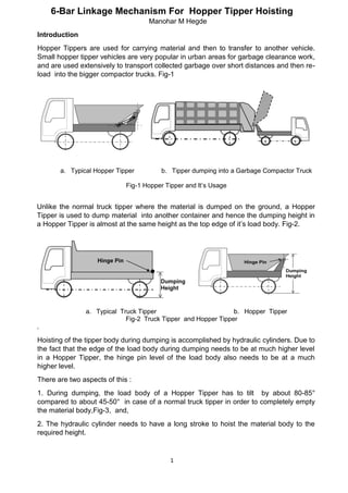
  • 1. 1 6-Bar Linkage Mechanism For Hopper Tipper Hoisting Manohar M Hegde Introduction Hopper Tippers are used for carrying material and then to transfer to another vehicle. Small hopper tipper vehicles are very popular in urban areas for garbage clearance work, and are used extensively to transport collected garbage over short distances and then re- load into the bigger compactor trucks. Fig-1 a. Typical Hopper Tipper b. Tipper dumping into a Garbage Compactor Truck Fig-1 Hopper Tipper and It’s Usage Unlike the normal truck tipper where the material is dumped on the ground, a Hopper Tipper is used to dump material into another container and hence the dumping height in a Hopper Tipper is almost at the same height as the top edge of it’s load body. Fig-2. a. Typical Truck Tipper b. Hopper Tipper Fig-2 Truck Tipper and Hopper Tipper . Hoisting of the tipper body during dumping is accomplished by hydraulic cylinders. Due to the fact that the edge of the load body during dumping needs to be at much higher level in a Hopper Tipper, the hinge pin level of the load body also needs to be at a much higher level. There are two aspects of this : 1. During dumping, the load body of a Hopper Tipper has to tilt by about 80-85° compared to about 45-50° in case of a normal truck tipper in order to completely empty the material body,Fig-3, and, 2. The hydraulic cylinder needs to have a long stroke to hoist the material body to the required height.
  • 2. 2 a. Typical Truck Tipper Dumping Action b. Hopper Tipper Dumping Action Fig-3 Comparison of Dumping Actions 4-Bar linkage mechanism is the most preferred arrangement to hoist a Hopper Tipper load body, mainly due to it’s simplicity. Hydraulic cylinder acts as a sliding pair. Most commonly used arrangement of linkage in today’s Hopper Tipper is shown in Fig-4 a. 4-Bar Mechanism in Normal Condition b. 4-Bar Mechanism During Dumping Condition Fig-4 Usage of a 4-Bar Mechanism for Hopper Tipper Hoisting Engineers while designing the hoisting system for a Hopper Tipper have to meet multiple objectives. One such objective is to limit the maximum cylinder length within target value. Another objective is to avoid high concentration of forces and stresses. Although a 4-Bar linkage can very well meet the basic functionality of hoisting the load body, and is most commonly used as well, there are situations when design engineers find it inadequate to meet the above mentioned specific design objectives. The configuration of the 4-Bar linkage currently used in most of the Hopper Tippers is not optimised, and results in fairly long cylinder stroke. For example, one popular model of a smallest Hopper Tipper in the
  • 3. 3 market has a minimum cylinder length of about 680mm and extended length of about 1030mm. Hence, alternative configurations of hoisting arrangement are desirable for linkage optimisation. In this article, 2 alternative arrangement of 4-Bar linkage are evaluated with respect to two criteria, namely, 1). maximum length of the hydraulic cylinder, and, 2). maximum reaction force on the load body hinge pin. The results are compared with the values obtained on existing 4-Bar arrangement. Further, a 6-Bar mechanism is designed and evaluated, and the results compared with the values obtained on existing and alternative proposals of 4-Bar mechanisms. Existing 4-Bar mechanism and also alternative 4-Bar arrangement are shown in Fig-5 a. Existing b. Alternative-1 c. Alternative-2 Fig-5 Existing and Alternative 4-Bar Mechanisms Problem Statement A very common objective during product design stage is to achieve the most compact equipment size possible. When hydraulic cylinders are used for tipper hoisting, shorter cylinder lengths are preferred. This will result in efficient packaging. This will also improve ease of assembly and ease of maintenance. Tippers are generally used in outdoor atmosphere, and hence are subjected to a lot of wear and tear. The pin joints used in a tipper mechanism are prone to rapid wear which leads to quicker failures of these joints. The maximum load on the pin and the amount of rotation are the major factors affecting the rate of wear. In a typical tipper hoisting mechanism, several pins are used (body hinge pin, cylinder anchor pins,etc) but the body hinge pin is the one which goes through the maximum rotation( 80-85° in case of Hopper Tippers). Hence, design engineers have to look for ways of keeping the static loads on the rotating pins, especially the load body hinge pin as low as possible in order to improve the life of the pins. This article focuses on the ways of reducing the force on the load body hinge pin. Methodology The location of the Center of Gravity (C.G.) of the loaded body was estimated based on the shape of the load body and type of material it carried. (Generally, urban refuse will have comparatively lesser density, and this needs to be taken into account while estimating the location of C.G.). The total load during hoisting (payload and weight of the
  • 4. 4 load body) was taken as acting through this C.G. Kinematic model of the hoisting linkage mechanism was set-up, and the design parameters were arrived at by iterations, to achieve the desired tipper body rotation. A total rotation of 85° was considered for the load body during hoisting, and the instantaneous values of length of the hydraulic cylinder(L) and vertical position of C.G.(H) were determined with respect to the angular orientation (θ) of the load body using kinematic relationships. Once the linkage dimensions were achieved, force analysis was carried out to determine the pin forces and the cylinder force. The methodology was verified by calculating the minimum and maximum cylinder lengths of an existing popular Hopper Tipper (using measured lengths of it’s links) and then comparing these values with the actual cylinder minimum and maximum lengths measured. Calculation of hinge pin force was then carried out to establish the reference value. The main objective of the investigation was to seek an alternative 4- Bar linkage mechanism resulting in lower levels of load body hinge pin force, while meeting the kinematic requirement (continuous movement of the load body with respect to the cylinder stroke). Secondary objective was to have shorter cylinder lengths. In addition, feasibility of using a 6-Bar mechanism, and the pros and cons of the same are also investigated. Analysis of existing 4-Bar linkage Fig-6 shows Hopper Tipper load body during normal and dumping conditions, and the corresponding orientations of the 4-Bar hoisting mechanism. a. Hopper Tipper in Normal and Dumping Conditions b. Orientation of 4-Bar Mechnaism Used for Hoisting Fig-6 4-Bar Mechanism Analysis Scheme
  • 5. 5 The following parameters, obtained from the measurement of an existing Hopper Tipper, were used for the analysis of existing 4-Bar mechanism : Sl No Parameter Symbol Value Unit Remarks 1 Total weight of body with material WLB 500 Kgs Fixed design parameter(Input) 2 Angular orientation of load body from normal position θ 0-85 Degrees Design parameter- Independent variable 3 Initial position of CG from hinge pin level H1 (-50) mm Dependent variable 4 Final position of CG from hinge pin level H2 (1100) mm Dependent variable 5 Distance between CG and body hinge pin (C.G. moment arm) R 1110 mm Fixed design parameter 6 Dimension – Horizontal distance between body hinge pin and cylinder anchor point on chassis xc 85 mm Primary design parameter 7 Dimension - Vertical distance between body hinge pin and cylinder anchor point on chassis yc 240 mm Primary design parameter 8 Dimension - Side of the triangle formed between C.G., body hinge pin and cylinder force application point on the load body. b 575 mm Secondary design parameter 9 Dimension - Side of the triangle formed between C.G., body hinge pin and cylinder force application point on the body. c 870 mm Secondary design parameter 10 Application Force in the hydraulic cylinder required to hoist load body Fc N Calculated (Output) 11 Reaction Force in the hinge pin of the load body. Fr N Calculated (Output) Table-1 Mathematically, cylinder stroke, cylinder force and pin reaction force are represented as: L= ʄ (θ,xc,yc,R,b,c) ; Fc = ʄ (WLB,L,θ,xc,yc,R,b,c) ; Fr = ʄ (WLB,Fc,L,xc,yc,R,b,c) The steps involved in calibrating the calculations are as follows : 1. Measure and record the linkage dimensions, dimensions of the load body, minimum and maximum cylinder lengths during normal and dumping conditions. 2. Using the measured values calculate the theoretical minimum and maximum lengths of the cylinder (Lmin, Lmax) 3. Check if the calculated values of Lmin and Lmax match with the measured values. 4. Once the calculation has been verified with the actual measured values, then, using the weight of the loaded body acting at the CG as input, carry out force resolution in the linkages to calculate the cylinder force and force at the load body hinge pin. For the example taken, the comparison between the measured and calculated values of cylinder lengths are given below : Sl No Parameter Measured value Calculated value 1 Minimum length of the cylinder, mm 680 684 2 Maximum length of the cylinder, mm 1030 1028 3 Maximum Hinge pin force, N Not applicable 30518 Table-2
  • 6. 6 The comparison shows that the methodology used for kinematic analysis is appropriate for the given purpose. Variation of load body hinge pin reaction force with respect to the rotation of the load body is shown in the graph Fig-7: Fig-7 Variation of Resultant Hinge Pin Force With Respect to Load Body Rotation Synthesis of new 4-Bar linkages and their analysis : Keeping the basic arrangement of link elements same, by changing the cylinder connection points two alternative 4 bar linkage arrangements were arrived at for evaluation.Fig-8 a. Existing a. Alternative-1 b. Alternative-2 Fig-8 Existing and Proposed Alternative 4-Bar Linkage Mechanisms The synthesis and analysis of new mechanisms were carried out as given below : 1. Parameters Xc and Yc were changed to move the anchor point of the cylinder. Similarly, keeping R and the relative position of C.G. in the load body same,parameters b and c were changed to alter the connection point of the cylinder with the load body. 2. For each set of the above parameters, cylinder minimum and maximum lengths were calculated to achieve 85° rotation of the load body. 3. Kinematic compatibility, like the ratio and/or difference between minimum and maximum cylinder lengths, minimum and maximum angles between adjacent links,etc, was considered. 4. By iteration, two feasible sets of parameters satisfying the kinematic compatibility were arrived at(Alternative-1 and Alternative-2). 0 5000 10000 15000 20000 25000 30000 35000 0 20 40 60 80 100 Force,N→ Load Body Tilt in Degrees
  • 7. 7 5. Force resolution was carried out for the final configurations to arrive at the cylinder force and the load body hinge pin force The results were compiled in the following table : Sl No Parameter Existing (calculated) Alternative-1 Alternative-2 1 Minimum length of the cylinder, mm 684 591 271 2 Maximum length of the cylinder, mm 1028 1014 420 3 Maximum Hinge pin force, N 30518 10963 36898 Table-3 Variation of load body hinge pin reaction force with respect to the rotation of the load body is shown in the graph.Fig-9 : Existing 4-Bar Linkage Alternative-1,4-Bar Linkage Alternative-2, 4-Bar Linkage Fig- 9 Comparison of Variation of Hinge Pin Force with Respect to Load Body Rotation Synthesis of a new 6-Bar linkage and it’s analysis : A 6-Bar linkage was conceived for adaptation, considering functionality, simplicity of kinematics and space utilisation. a. Watt II Mechanism b. Adaptation on Vehicle c. Kinematic Representation and Analysis Scheme Fig -10 6-Bar Mechanism Analysis Scheme 0 10000 20000 30000 40000 0 50 100 Force,N→ Load Body Tilt in Degrees 0 2000 4000 6000 8000 10000 12000 0 50 100 Force,N→ Load Body Tilt in Degrees 0 10000 20000 30000 40000 0 50 100 Force,N→ Load Body Tilt in Degrees
  • 8. 8 Synthesis of a 6-Bar linkage to suit an application is more challenging since the number of design variables required for the solution are more. Keeping this in mind, a standard Watt II type linkage was adapted for this application. The increased complexity of analysis is reflected in the mathematical expression for cylinder stroke, cylinder force, and pin reaction force : L= ʄ (θ,xc,yc,xp,yp,R,b,c,l,m,n,p) ; Fc = ʄ (WLB,L,θ,xc,yc, xp,yp,R,b,c,l,m,n,p) Fr = ʄ (WLB,L,θ,xc,yc, xp,yp,R,b,c,l,m,n,p) A brief description of mechanism synthesis and analysis procedure is given below : 1. A standard Watt II linkage is adapted. The mechanism consists of 2 ternary links,one binary link and a sliding pair(hydraulic cylinder), and the machine chassis forming the common fixed link. Fig-10. Parameters Xc ,Yc ,Xp and Yp were decided on the basis of space available on vehicle chassis for the fixed hinges. Similarly, keeping R and the relative position of C.G in the load body same,parameters b and c were changed to alter the connection point of the cylinder with the load body. 2. For each set of the above parameters, cylinder minimum and maximum lengths were calculated to achieve the required 85° rotation of the load body. 3. Kinematic compatibility, like the ratio and/or difference between minimum and maximum cylinder lengths, minimum and maximum angles between adjacent links,etc were ensured. 4. By iteration, two feasible sets of parameters satisfying the kinematic compatibility were arrived at. 5. Force resolution was carried out for the final configuration to arrive at the cylinder force and the hinge pin reaction force Variation of load body hinge pin reaction force with respect to the rotation of the load body when a 6-Bar linkage is adapted is shown in the graph. Fig-11 : Fig-11 6-Bar Linkage. Variation of Resultant Hinge Pin Force with Respect to Load Body Rotation 0 5000 10000 15000 20000 25000 0 20 40 60 80 100 Force,N→ Load Body Tilt in Degrees
  • 9. 9 Result : The results of the 4-Bar and 6-Bar linkage were compiled in the following table : Sl No Parameter Existing 4-Bar (calculated) Alternative-1 4-Bar Alternative-2 4-Bar Alternative-3 6-Bar 1 Minimum length of the cylinder, mm 684 591 271 255 2 Maximum length of the cylinder, mm 1028 1014 420 432 3 Maximum hinge pin force, N 30518 10963 36898 21383 Table-4 Discussion : There are several ways in which a 4-Bar linkage can be used to accomplish the task of hoisting a load body in a Hopper Tipper. The two alternative linkage arrangement proposed are found to be functionally satisfactory (hoisting to a rotation of 85°). However, looking at the tabulated results and the performance graphs, it is clear that design engineers who want to meet the twin objectives of compact cylinder size and lower hinge pin reaction force will have to compromise on at least one of them. Hence, exploring other options, like a 6-Bar linkage arrangement for hoisting is desirable. In this investigation only one arrangement of a 6-Bar linkage to replace the 4-Bar linkage was studied. Comparing the results of analysis with those of 4-Bar linkages, it is evident that, both the design goals could be achieved with a 6-Bar linkage. It may be noted here that, prima-facie, a 6-Bar linkage has more number of parts, and hence costs more compared to a 4-Bar linkage. However, two aspects of a 6-Bar linkage still make it worth considering as an option –1). possibility of optimising the link sizes to achieve shorter cylinder sizes and lower pin forces compared to what has been shown in this article, and,2). to use variants of the 6-Bar linkage to make the Hopper Tipper versatile. Conclusion : 1. Most popular Hopper Tippers used today have 4-Bar linkage with hydraulic cylinder for load body hoisting. Although the linkage arrangement is functionally adequate, it results in longer cylinder and also higher hinge pin reaction force. . 2. Out of the two alternative 4-Bar linkages considered, one (alternative-1) achieves a reduced hinge pin reaction force, using almost same cylinder length as the existing arrangement. 3. The second alternative gives the most compact packaging arrangement due to shorter cylinder, but results in much higher hinge pin reaction force.. 4. A 6-bar linkage arrangement results in shorter cylinder length as well as lower hinge pin reaction force. But, on the flip side,a 6-Bar arrangement requires more number of components.. 5. Scope for further study - 1). A careful optimisation study can result in even more efficient design - occupying lesser space, shorter cylinder length and lesser pin reaction force. 2). Development of variants of 6-Bar mechanisms to use in Hopper Tippers targeting new applications.