
Recommended
More Related Content
What's hot
What's hot (20)
Similar to 4th Indonesia International Geothermal Convention Proceedings
Similar to 4th Indonesia International Geothermal Convention Proceedings (20)
4th Indonesia International Geothermal Convention Proceedings
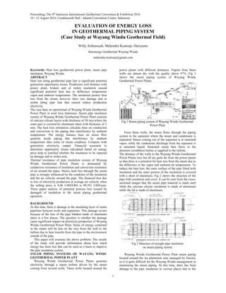
- 1. Proceedings The 4th Indonesia International Geothermal Convention & Exhibition 2016 10 - 12 August 2016, Cendrawasih Hall - Jakarta Convention Center, Indonesia 1 EVALUATION OF ENERGY LOSS IN GEOTHERMAL PIPING SYSTEM (Case Study at Wayang Windu Geothermal Field) Willy Ardiansyah, Mahendra Kuntoaji, Hariyanto Starenergy Geothermal Wayang Windu mahendra.kuntoaji@gmail.com Keywords: Heat loss geothermal power plant, steam pipe insulation, Wayang Windu. ABSTRACT Heat lost along geothermal pipe line is significant potential generation opportunity losses. Production well distance with power plant, broken and or stolen insulation caused significant potential heat due to difference temperature vapor and ambient temperature. The insulation protect heat loss from the steam, however there was damage and or stolen along pipe line that caused reduce production electricity. The case base on operational of Wayang Windu Geothermal Power Plant in west Java Indonesia. Steam pipe insulation system of Wayang Windu Geothermal Power Plant consists of calcium silicate layers with thickness of 50 mm where the outer part is covered by aluminum sheet with thickness of 2 mm. The heat loss estimation calculate base on conduction and convection to the piping that interference by ambient temperature. The energy balance base on steam flow quantity inside piping that interference by ambient temperature thus some of steam condense. Compere with generation electricity output. Financial assement to determine opportunity losses calculated based on energy price help to justified whether the insulation to be repaired on damage and or stolen area. Thermal resistance of pipe insulation system of Wayang Windu Geothermal Power Plants is dominated by conduction resistance of insulation and convection resistance of air around the pipes. Hence, heat loss through the steam pipe is strongly influenced by the condition of the insulation and the air velocity around the pipe. The financial loss due to loss of electricity production at average air velocity when the selling price is 0.06 USD/kWh is 99,781 USD/year. These paper analyze of potential process loss caused by damaged of insulation in the steam piping geothermal operation. BACKGROUND At this time, there is damage to the insulating layer of steam pipelines between wells and separators. This damage occurs because of the loss of the pipe blanket made of aluminum sheet in a few places. The question is whether the damage cause significant impact on electricity production of Wayang Windu Geothermal Power Plant. Some of energy contained in the steam will be lost on the way from the well to the turbine due to heat transfer from the pipe to the environment outside of the pipe. This paper will examine the above problem. The results of the study will provide information about how much energy has been lost that can be used as a basis to improve the pipe insulation system. STEAM PIPING SYSTEMS OF WAYANG WINDU GEOTHERMAL POWER PLANT Wayang Windu Geothermal Power Plants generate electricity through a steam turbine driven by the steam coming from several wells. These wells located around the power plants with different distances. Vapors from these wells are almost dry with the quality above 97%. Fig 1 shows the steam piping system of Wayang Windu Geothermal Power Plants. Fig 1 Steam piping system of Wayang Windu Geothermal Power Plant From these wells, the steam flows through the piping system to the separator where the steam and condensate is separated. Steam coming out of the separator is at saturated vapor, while the condensate discharge from the separator is at saturated liquid. Saturated steam then flows to the demister (scrubbers) before is supplied to the turbine. The distance of the wells to the Wayang Windu Geothermal Power Plants vary but all are quite far from the power plants so that there is a potential for heat loss from the steam due to the difference in the vapor and ambient air temperature. To reduce the heat loss, the outer surface of the pipe fitted with insulation and the outer portion of the insulation is covered with a sheet of aluminum. Fig 2 shows the structure of the pipe with insulation and cover. It can be seen from the cross- sectional images that the steam pipe material is made steel while the calcium silicate insulation is made of aluminum while the lid is made of aluminum. Fig 2 Structure of straight pipe insulation on steam piping system Wayang Windu Geothermal Power Plant steam piping located around the tea plantation area managed by forestry so it is quite difficult for the Wayang Windu management in monitoring the steam piping. At this time, there has been damage to the pipe insulation in various places due to the
- 2. Proceedings The 4th Indonesia International Geothermal Convention & Exhibition 2016 10 - 12 August 2016, Cendrawasih Hall - Jakarta Convention Center, Indonesia 2 loss of the insulating cover made of aluminum. If this cover is broken then the insulation made of calcium silicate will be separated from the outer surface of the pipe. As a result, the outer surface of the pipe will be exposed to the surrounding. Damage to the pipe insulation will cause a rise in heat loss of the steam. Because the steam coming from the well is at two-phase fluid (saturated vapor and saturated liquid), the increase in heat loss will increase the rate of condensation of the steam. The amount of liquid that is formed as steam flowing from the well to the separator will increase. Hence, the fraction of steam from the top of the separator will be reduced proportional to the fraction of liquid that comes out from the bottom of the separator. Because the vapor fraction is reduced due to the rate of condensation, the steam flowing to the turbine will also be reduced. As a result, production of electricity of the power plant will be reduced as well. Since the end product of the geothermal power plant is electrical energy, steam pipe insulation damage that reduces production of electricity should be repaired. However, because this repair needs costs, it is necessary to do the calculations to determine its financials feasibility. This report provides the information necessary to perform financial calculations later so that decision to repair the insulation damaged can be made properly. PRINCIPLES OF HEAT LOSS ESTIMATION The rate of heat loss from the steam flowing inside the steam piping system can be estimated from the calculation of heat rate by conduction and convection. The heat loss due to radiation can be neglected since the surface temperature of the outside pipe is quite low (below 200oC). Conduction heat transfer rate can be estimated from the following equation: Where: • Qconduction : conduction heat transfer rate • k : thermal conductivity of material • As : heat transfer surface area • T1 and T2 : high and low temperature • ∆x : thickness of material For geometry with curved surfaces and outer and inner diameter d1 and d2 respectively, conduction heat transfer rate equation is as follows: With L is the length of the segment that plays a role in heat transfer process. While the convection heat transfer rate can be estimated from the following equation: Where: • qconvection : convection heat transfer rate • h : convection heat transfer coefficient • As : heat transfer surface area • Ts : surface temperature • Tair : surrounding air temperature To facilitate the calculation of the rate of heat transfer through conduction and convection processes simultaneously, the rate of heat transfer equation through a pipe can be expressed in terms of the analogy of electricity (Ohm's Law) as follows: Where thermal resistance of conduction and convection are: For the calculation of heat transfer rate from the steam to the surrounding in the steam piping system of Wayang Windu Geothermal Power Plant, Fig 3 can be used. The figure describes the process of heat transfer from the vapor to the air through an uninsulated pipes with its thermal circuit. R1 and R4 show the thermal resistance of conduction and convection respectively. Fig 3 Thermal circuit for uninsulated pipe Then the rate of heat transfer from the vapor to the air can be calculated as follows: where Rtotal is the sum of conduction resistance R4 and convection resistance R1, which is: For an insulated pipe, the heat transfer rate calculation can be performed by observing Fig 4. Fig 4 Thermal circuit for an insulated pipe. The rate of heat transfer from the vapor to the air can be calculated as follows: where Rtotal is the sum of conduction resistance R2, R3, and R4, and convection resistance R1, which is: where: • d1 : inner diameter of pipe • d2 : outer diameter of pipe
- 3. 3 • d3 : outer diameter of insulation • d4 : outer diameter of lid • k : thermal conductivity of each materials Convection coefficient in convection thermal resistance equation must be estimated before the resistance value can be calculated. Estimated value of the convection heat transfer coefficient depends on the geometry, fluid properties, and the condition of the air around the pipe. When air flows at a certain velocity then it is called forced convection while if air is not flowing then it is called free convection. For forced convection, correlations to predict the convection heat transfer coefficient is as follows: with: V is the velocity of the air around the pipe with diameter D and k and Ʋ are conductivity and kinematic viscosity of the air, respectively. Pr is the Prandtl number of air. From the above relationship the value of the convection heat transfer coefficient h can be estimated. ENERGY BALANCE OF STEAM PIPING SYSTEMS Loss of heat energy from the steam to the surrounding air in the piping system of Wayang Windu Geothermal Power Plants need to be converted into loss of electricity production. As can be seen in Fig 1, there are many wells that produce steam which eventually collected and flow into the separator in the power plants area. Energy balance calculation can be simplified by defining the system boundary as shown in Fig 5. 1 32 qloss,1 qloss,2 Fig 5 System boundary to simplify the calculation of heat balance Steam from various wells after passing the measuring devices (flow meter) is described as out of the component (1) and then enter component (2) which describes the steam piping system of Wayang Windu Geothermal Power Plants. Then, the steam exits the piping system and enters components (3) which describes separator. The focus of attention for the analysis of electricity production loss due to heat loss in steam piping system is the component (2). qloss,1 is the rate of heat loss in good insulated pipe conditions along L and qloss,2 is the rate of heat loss in damaged pipe insulation condition along L. If the pipe insulation is damaged then the rate of heat loss will increase by qloss,2 and when the steam exits the component (2), part of the steam will condenses at a rate comparable to the rate of heat loss. Thus, the rate of steam entering the separator will decrease proportional to the rate of addition of the condensation. The energy balance for the steam piping system of Wayang Windu Geothermal Power Plants for damaged insulation condition can be expressed by the following relationship: While the energy balance for the piping system with good insulation conditions are as follows: Addition of condensation rate due to the heat loss qloss,2 can be determined from the following relationship: With hfg is heat of condensation at operational pressure. The amount of electricity production loss due to damage to the pipe insulation can be determined from the following equation: Thus, electricity production loss can be determined directly if the addition of condensation rate and turbine entry and exit enthalpy are known. RESULT AND DISCUSSIONS The increase in the heat loss due to damaged insulation can be determined from the calculation of heat loss at damaged insulation condition minus the heat loss at good insulation condition. For Unit 2, from Table 4 and Table 5 it can be shown that the total heat loss in good insulation condition is 61,9 kW and in damaged insulation condition is 304,2 kW. Thus, the increase in heat loss 304,2 kW – 61,9 kW = 242,3 kW. For the calculation of the other conditions, the procedure is the same and only changed the air velocity. Increase in heat loss due to damaged insulation at various air velocities are presented in Table 6 for Unit 1 and Table 7 for Unit 2. From these calculations it can be seen that the heat loss is strongly influenced by the condition of the pipe insulation and air velocity around the pipe. For the same total length of damaged insulation, the higher the air velocity, the higher heat loss from the steam to the surrounding air will be. Table 1 Calculation of heat loss at average air velocity at good insulation (Unit 2) ØDo ØDi h R1 R2 R3 R4 Rtotal qloss AREA DRAWING LENGTH(m) (mm) (mm) (W/m2K) (K/W) (K/W) (K/W) (K/W) (K/W) (kW) WW2-ME-70-104 9 914.40 882.64 66654 183.8 4.75 3.63197E-05 0.031643317 3.39484E-07 0.00771 0.03939 4.34 9 914.40 882.64 66654 183.8 4.75 3.63197E-05 0.031643317 3.39484E-07 0.00771 0.03939 4.34 4 914.40 882.64 66654 183.8 4.75 8.17193E-05 0.071197464 7.6384E-07 0.017348 0.088628 1.93 13.2 914.40 882.64 66654 183.8 4.75 2.47634E-05 0.021574989 2.31467E-07 0.005257 0.026857 6.37 18.6 914.40 882.64 66654 183.8 4.75 1.7574E-05 0.015311283 1.64267E-07 0.003731 0.01906 8.97 20.6 914.40 882.64 66654 183.8 4.75 1.58678E-05 0.01382475 1.48318E-07 0.003369 0.017209 9.94 14.901 914.40 882.64 66654 183.8 4.75 2.19366E-05 0.01911213 2.05044E-07 0.004657 0.023791 7.19 WW2-ME-70-105 20.1 914.40 882.64 66654 183.8 4.75 1.62625E-05 0.01416865 1.52008E-07 0.003452 0.017637 9.70 7.92 914.40 882.64 66654 183.8 4.75 4.12724E-05 0.035958315 3.85778E-07 0.008762 0.044761 3.82 WW2-ME-70-106 11 914.40 882.64 66654 183.8 4.75 2.97161E-05 0.025889987 2.7776E-07 0.006308 0.032228 5.31 128.321 Totalheatloss U2 61.9 ReD NuD TotalLength LISTOFLOSTCLADDING MBBtoJ.20 Table 2 Calculation of heat loss at average air velocity and damaged insulation (Unit 2) ØDo ØDi h R1 R4 Rtotal qloss AREA DRAWING Service LENGTH(m) (mm) (mm) (W/m2K) (K/W) (K/W) (K/W) (kW) WW2-ME-70-104 TwoPhase Mains 9 914.40 882.64 59847 168.5 4.847 3.63197E-05 0.007979 0.008016 21.33 9 914.40 882.64 59847 168.5 4.847 3.63197E-05 0.007979 0.008016 21.33 4 914.40 882.64 59847 168.5 4.847 8.17193E-05 0.017953 0.018035 9.48 13.2 914.40 882.64 59847 168.5 4.847 2.47634E-05 0.00544 0.005465 31.29 18.6 914.40 882.64 59847 168.5 4.847 1.7574E-05 0.003861 0.003878 44.09 20.6 914.40 882.64 59847 168.5 4.847 1.58678E-05 0.003486 0.003502 48.83 14.901 914.40 882.64 59847 168.5 4.847 2.19366E-05 0.004819 0.004841 35.32 WW2-ME-70-105 TwoPhase Mains 20.1 914.40 882.64 59847 168.5 4.847 1.62625E-05 0.003573 0.003589 47.65 7.92 914.40 882.64 59847 168.5 4.847 4.12724E-05 0.009067 0.009109 18.77 WW2-ME-70-106 TwoPhase Mains 11 914.40 882.64 59847 168.5 4.847 2.97161E-05 0.006528 0.006558 26.07 128.3 Totalheatloss U2 304.2 ReD NuD LISTOFLOSTCLADDING MBBtoJ.20 Total Length
- 4. Proceedings The 4th Indonesia International Geothermal Convention & Exhibition 2016 10 - 12 August 2016, Cendrawasih Hall - Jakarta Convention Center, Indonesia 4 Table 3 Increase in heat loss at various air velocity (Unit 1) Air Velocity (m/s) Heat Loss Good Insulation (kW) Heat Loss damaged Insulation (kW) Increase in Heat Loss (kW) Remark 0 68,8 126,3 57,5 Minimum 1,04 119,5 586,6 467,1 Average 2,97 134,5 1357,4 1222,9 Maximum Table 4 Increase in heat loss at various air velocity (Unit 2) Air Velocity (m/s) Heat Loss Good Insulation (kW) Heat Loss damaged Insulation (kW) Increase in Heat Loss (kW) Remark 0 35,7 65,6 29,9 Minimum 1,04 61,9 304,2 242,3 Average 2,97 69,7 703,7 634,0 Maximum Loss of power production can be determined from the increase in heat loss. As explained in the previous section, the increase in heat loss will increase the rate of condensation of steam in the pipe from the wells to the separator. This section presents an example of the calculation of loss of electricity production at average air velocity. From the previous calculations it is known that for Unit 1, the increase in heat loss due to damage of the pipe insulation on the average air velocity is equal to 467,1 kW. On average vapor pressure of 19.92 bara (or 19.12 barg, assumed atmospheric pressure of 0.8 bara), condensation heat of water is equal to 1891 kJ/kg. Thus, the addition rate of condensation can be determined as: Loss of electricity production for Unit 1 and Unit 2 due to steam rate reduction is calculated with the following assumptions: • Turbine adibatic efficiency: 80,2% (Unit 1) and 0,792 (Unit 2) • Turbine mechanical efiiciency: 98,9% • Generator efficiency: 98,7% • Steam Inlet pressure to the turbine: 10,4 bara (Unit 1) and 10,425 (Unit 2) • Steam Inlet quality to the turbine: saturated vapor • Steam outlet pressure from the turbine: 0,12 bara (Unit 1) and 0,11 (Unit 2) The calculation are given in separated spreadsheet attached to this report where additional condensation rate and loss of electricity production can be found. For both Unit 1 and Unit 2, additional condensation rate and loss of electricity production is summarized in Table 11. Table 5 Summary of additional condensation rate and loss of electricity production Unit 1 Unit 2 Unit 1 Unit 2 Total 0 0.029 0.015 15.3 8.1 23.4 Minimum 1,04 0.235 0.123 124.6 65.2 189.8 Average 2,97 0.616 0.322 326.5 170.7 497.2 Maximum Additional Condensation Rate (kg/s) Air Velocity (m/s) Remark Loss of Electricity Production (kW) As can be seen in Table 8, the maximum loss of electricity production for Unit 1 and Unit 2 are 326,5 kW and 170,7 kW, respectively. Although at a maximum air velocity, the increase in heat loss from the steam to the air reaches 1222,9 kW for Unit 1 and 634,0 kW for Unit 2, the maximum loss of power production is only around 28% of the maximum increase in heat loss. This is because the latent heat of condensation is much greater than the decrease in the enthalpy of the steam expansion process within the turbine. It should be noted here that the loss of electricity production is only for the damaged section of pipe insulation, not for the entire pipelines from the wells to the turbines of Wayang Windu Geothermal Power Plants. To give a picture of financial loss due to loss of electricity production, it is assumed that electricity selling price is 6 cUSD/kWh. Taking average air velocity as basis of calculation, the financial loss per year becomes: 0.06 USD/kWh x 189.8 kW x 24 h x 365 h/year = 99,781 USD/year. CONCLUSIONS • Steam pipe insulation system of Wayang Windu Geothermal Power Plant consists of calcium silicate layers with thickness of 50 mm where the outer part is covered by aluminum sheet with thickness of 2 mm. • Thermal resistance of pipe insulation system of Wayang Windu Geothermal Power Plants is dominated by conduction resistance of insulation and convection resistance of air around the pipes. Hence, heat loss through the steam pipe is strongly influenced by the condition of the insulation and the air velocity around the pipe. • The financial loss due to loss of electricity production at average air velocity when the selling price is 0.06 USD/kWh is 99,781 USD/year. REFERENCES [1] Introduction to Heat Transfer, Incropera and DeWitt Sixth Edition, John Wiley and Sons Inc., 2011. [2] Fundamental of Thermodynamics Engineering, Moran and Saphiro 5th Edition, John Wiley and Sons, 2006. GLOSSARY • Vapor is the gaseous phase of water. Water vapor can be produced from the evaporation or boiling of liquid water or from the sublimation of ice. • Conduction is transferring some of heat to these neighboring particles trough a conductive material. • Convection, is the transfer of heat from one place to another by the movement of fluids, a process that is essentially the transfer of heat via mass transfer.