
Recommended
More Related Content
What's hot
What's hot (20)
Similar to Beyond-the-Horizon Cruise Missile Defense Demonstration
Similar to Beyond-the-Horizon Cruise Missile Defense Demonstration (20)
More from Lsquirrel
More from Lsquirrel (20)
Recently uploaded
Recently uploaded (20)
Beyond-the-Horizon Cruise Missile Defense Demonstration
- 1. JOHNS HOPKINS APL TECHNICAL DIGEST, VOLUME 18, NUMBER 4 (1997) 501 MOUNTAIN TOP: BEYOND-THE-HORIZON CRUISE MISSILE DEFENSE T Mountain Top: Beyond-the-Horizon Cruise Missile Defense William H. Zinger and Jerry A. Krill he Cruise Missile Defense Advanced Concept Technology Demonstration, known as Mountain Top, was successfully completed at Kauai, Hawaii, during January and February 1996. The demonstration featured a new type of cooperative engagement known as “forward pass,” made possible by the Cooperative Engagement Capability, in which low-flying drones were engaged beyond the horizon of an Aegis ship for greatly increased engagement range. Although the Navy performed the forward pass cooperative engagements alone, the Marine Corps, Air Force, and Army participated in other major joint-services exercises. Most significantly, the concept of a surface- launched, air-supported engagement of cruise missiles was validated and has provided the impetus for follow-on joint-services pursuit of an extended, beyond-the-horizon engagement capability for defense of land sites from land-, air-, and sea-based missile defense systems. This article describes the background, objectives, conduct, and results of the Mountain Top test operations. Also detailed are the systems engineering concepts, system configurations, and the test and evaluation process that went into the planning, conduct, and analysis of the many complex experiments of the Advanced Concept Technology Demonstration. (Keywords: Beyond the horizon, Cooperative engagement, Forward pass, Joint services, Mountain Top, Overland cruise missile defense.) BACKGROUND The concept of intercepting low-flying targets by ship-launched missiles beyond the ship’s horizon with the aid of an airborne platform was considered over two decades ago. By removing the limitation of the ship’s radar horizon, such a concept envisioned the intercep- tion of targets much farther from the defended and engaging units, allowing time for additional engage- ments if necessary. Figure 1 illustrates the evolution of the “forward pass” concept. The earliest version of the concept, examined at APL in the mid-1970s as part of the Battle Group Anti- Air Warfare Coordination Program, embodied prima- rily the element of beyond-the-horizon guidance. In this case, a Standard Missile (SM) would be directed via the ship’s missile midcourse control link to the vicinity of an F-14 fighter. The fighter’s fire control radar, modified for this role, would illuminate the tar- get, allowing the missile to home on the reflected il- lumination from the target. A modified form of forward pass emerged in the late 1970s to early 1980s during a series of “outer air battle” studies, which addressed next-generation Navy battle group air defense requirements against Soviet bombers armed with long-range antiship cruise missiles. If the bombers could be intercepted before they approached to within range of launching their missiles at U.S. TECHNOLOGY DEMONSTRATION
- 2. W. H. ZINGER AND J. A. KRILL 502 JOHNS HOPKINS APL TECHNICAL DIGEST, VOLUME 18, NUMBER 4 (1997) ships, a critical new layer of defense would be provided. This variant of forward pass featured a conceptual, long- range ramjet missile that could be launched from an Aegis cruiser and flown toward a carrier-based surveil- lance and fire control aircraft. The aircraft would carry advanced, long-range sensors to detect bombers and to take over midcourse missile control from the ship via an onboard aircraft-to-missile link. The missile was envisioned to have a multisensor homing seeker capable of locking onto a target from long distances. This form of the concept (Fig. 1, center) was known as “midcourse handover” in contrast to the “remote illumination” approach of the F-14 concept. From these outer air battle studies, in which APL was a prominent partic- ipant, a requirement for a long-range form of SM (now known as SM-2 Block IV) emerged along with the need for a “cooperative engagement link.” The Laboratory participated in yet another series of related studies in the mid- to late 1980s, centered around the use of an airship to carry weapon system elements comparable in function to the phased array radar and illuminators of an Aegis cruiser, but with reduced weight and new features for missile control. Key among those features was the use of a “multifunc- tion” phased array system as both the fire control radar and illuminator. This feature provided multiplexed il- lumination of targets, thus allowing simultaneous hom- ing of several SM-2 missiles. Analysis showed that, given sufficient equipment weight reduction and power capacity, an airship so equipped and operating at an altitude of over 10,000 ft could greatly extend the effective surveillance and engagement range against low-altitude cruise missiles. This last example of forward pass can be seen as a hybrid between a remote-illumination forward pass and a form of cooperative engagement then being designed for the Cooperative Engagement Capability1 (CEC; see the boxed insert) known as engagement on remote data (EOR). An EOR capability allows a ship to fire an SM- 2 missile and direct the missile midcourse and terminal homing illumination using data from remote rather than own-ship sensors. For this concept, the airship would serve as both the remote data source for EOR and as the remote homing illuminator in the forward pass mode. This became the form of cooperative engagement con- sidered for the eventual Mountain Top tests. With the end of the Cold War and the advent of littoral environment scenarios, the low-altitude cruise missile threat became even more important, so that a beyond-the-horizon intercept capability remained very attractive. A variety of air platform candidates emerged including large tethered aerostats, wide-body aircraft, and a network of sensors from multiple smaller (manned or unmanned) aircraft linked via the CEC. An example of a concept using ship-launched aircraft networked with CEC is shown in Fig. 2. MOUNTAIN TOP Demonstration The potential operational advantages of a forward pass capability led senior Navy and DoD officials to conclude in 1993 that the likely payoff of an airborne unit to extend surface-launched missile engagement range was sufficiently compelling to explore as the initial stage of an Advanced Concept Technology Demonstration (ACTD). This ACTD stage eventually featured two sets of test operations, which are described in detail later in this article. • Set1comprisedbeyond-the-horizonNavytests(Phase 1) and Army tests (Phase 2). • Set 2, known as Enhanced Scenarios, involved par- ticipation of the Navy, Marine Corps, Army, and Air Force in joint exercises: arrival on the scene (Phase 1),defenseagainstshore-basedattacks(Phase2),and joint littoral operations (Phase 3). The organizations and participants in the ACTD are presented in Table 1. (The boxed insert, APL Moun- tain Top Team, lists the Laboratory personnel who participated in the formal testing.) Mid-1970s Mid- to late 1980sLate 1970s to early 1980s Figure 1. Evolution of the forward pass concept, i.e., the concept of intercepting missiles attacking from beyond a ship’s horizon with the aid of airborne radars: in the mid-1970s, aircraft illumination of the target for missile semiactive homing; from the late 1970s to early 1980s, aircraft detection of the target and guided missile midcourse to multimode homing; by the mid- to late 1980s, aircraft detection of the target and guided missile midcourse, and illumination of the target for pulsed semiactive missile homing.
- 3. JOHNS HOPKINS APL TECHNICAL DIGEST, VOLUME 18, NUMBER 4 (1997) 503 MOUNTAIN TOP: BEYOND-THE-HORIZON CRUISE MISSILE DEFENSE Figure 2. Illustration of the land-attack cruise missile defense concept in which aircraft are networked via the Cooperative Engagement Capability to form a composite airborne surveillance and fire control radar/terminal illuminator capability. This allows sea- and land-based units to send an intercepting missile beyond the firing unit’s horizon. Engagement is thus possible at unprecedented ranges, thereby providing extended defense against land-attack cruise missiles. Table 1. Major players in the Mountain Top ACTD.a Participant/organization Function Navy CEC Program Manager ACTD program management Office of Naval Research Acting sponsor APL and MIT Lincoln Labs Lead laboratories APL Technical Direction Agent for CEC and SM-2 Raytheon E-Systems CEC prime contractor Lockheed Martin Aegis prime contractor Hughes Aircraft Co. SM-2 prime contractor Naval Weapons Support Center Equipment and site support Naval Sea Systems Command Tartar fire control radar support Pacific Missile Range Facility Range operations support a Aegis and Standard Missile program offices also participated. Patriot battery Track/ illuminate Search Search Aegis ship Aegis/Standard Missile-2 midcourse uplink/downlink Cue Patriot missile Standard Missile
- 4. W. H. ZINGER AND J. A. KRILL 504 JOHNS HOPKINS APL TECHNICAL DIGEST, VOLUME 18, NUMBER 4 (1997) THE COOPERATIVE ENGAGEMENT CAPABILITY The Cooperative Engagement Capability (CEC) has been developed to network sensors and weapon systems in a manner that allows a set of geographically diverse air defense systems of various types to operate as if they were a single entity, but with performance advantages that accrue from the exploitation of their intrinsic diversities (i.e., locations and sensor characteristics). A full description of CEC is available in a previous issue of the Technical Digest.1 For the convenience of the reader, the primary CEC char- acteristics are briefly summarized here. The CEC system consists of two subsystems: the Coop- erative Engagement Processor (CEP) and a data transfer element known as the Data Distribution System (DDS). In Fig. A, the CEC is shown connected to the Aegis combat system, for example. The CEP provides its combatant’s weapon system with a composite track picture as well as recommended target identity. This is accomplished by using local and remote sensor measurements and information friend or foe (IFF) responses, which are exchanged via the DDS, to create a common air picture that is more complete and more accurate than one obtained from the best con- tributing sensor. With this quality information, a unit may engage using only remote data, even if the target is fast and maneuvering. The DDS performs the networking functions of automatically establishing and maintaining a secure net- work for rapid exchange of target position measurements and associated data messages among all cooperating com- batants. The CEP on a given combatant is interfaced to its prin- cipal sensors, from which it receives radar or IFF target reports and to which it provides data for special acquisition or gating to acquire targets not locally held. All sensor or IFF reports associated with each assigned track are ex- changed via the DDS with other cooperating units. The exchanged data include, as appropriate, target range, bear- ing, elevation, Doppler (if available), sensor type, and as- sociated track number. Unit position data obtained from inertial navigation data, DDS-to-DDS measurements, and other pertinent sources are also exchanged. The CEP grid- lock function computes the precise relative positions of cooperating units and calibrates sensor angular and range alignments by correlating reported positions of common, multiply tracked targets. Using these data, the CEP develops an optimized com- posite track of each target by applying a quality-weighted combination of all data sources via a Kalman filter. Con- tinual tests for target splits and merges are made at the measurement input level. These track data are provided to the combatant’s weapon system for fire control use and to its command/control element. The exchange and process- ing of unprocessed target measurement data—rather than the exchange of track data (with its inevitable lags and corruption by fades), as is common to tactical link net- works—is a key feature of the CEC concept and is respon- sible for its ability to generate fire control–quality data for sensor/weapon acquisition and missile guidance. The CEP also exchanges engagement status data among cooperating weapon systems. In the future, it will compute the relative engageability of undesignated targets by the various weapon systems for recommendation of weapons engagement assignments among networked units. DDS elements, using their directive phased array an- tennas, automatically establish and maintain a communi- cation network among all cooperating units by synchro- nously switching their transmit and receive beams among pairs of units in parallel (Fig. B). Because each DDS pos- sesses a phased array with a single beam for either trans- mission or reception, each unit can only point its beam to connect (transmit or receive) to one other DDS at a time. Each connection event involves one unit transmitting through its beam to another unit and the other unit point- ing its beam at the transmitting unit to receive from it. This transmit/receive beam connectivity is generally performed in parallel among pairs in the network at precise times via the DDS cesium clocks using a common, adaptive algo- rithm. Different pairings occur every “frame,” a small sub- second block of time. If a connectivity path or a unit is lost CEC Weapon control system SPY-1B radar IFF CEP DDS Command/ decision Displays Command/ control links SPS-49 radar Figure A. CEC interfaces to the Aegis combat system. Objectives The Mountain Top ACTD management plan2 iden- tified the Navy, Army, and the Advanced Research Projects Agency (ARPA) as the primary participants and was approved by senior Army, Navy, DoD, and Ballistic Missile Defense Organization officials. The objective of . . . (Mountain Top) is to demon- strate the potential for significant enhancements to air defense capabilities by integrating Navy/Army/ARPA technology developments and existing air defense sys- tems. The goal is to detect, track, and successfully engage cruise missiles at ranges beyond the radar line of sight of surface-based air defense units, and provide an oppor- tunity to assess joint doctrine and concepts of air defense operation.2 Toward this objective the plan required an explora- tion of three new capabilities2 :
- 5. JOHNS HOPKINS APL TECHNICAL DIGEST, VOLUME 18, NUMBER 4 (1997) 505 MOUNTAIN TOP: BEYOND-THE-HORIZON CRUISE MISSILE DEFENSE (e.g., because of equipment failure, excess jamming, or propagation fade), the loss of connectivity is communicat- ed throughout the network, and the common algorithms adjust the schedules and any relay sequences identically and automatically at each DDS. Antenna directivity and relatively high transmitter pow- er provide the required countermeasures immunity and margin against propagation fading, while maintaining a high data rate and a low error rate. The phased array design permits the near-instantaneous beam pointing necessary to meet stringent subsecond timing requirements associated with sensor measurements. The utilization of a narrowbeam- directed phased array antenna for both transmission and reception is unprecedented for a mobile communication system, as is the unique scheduling and control process used by the DDS. Transmit Transmit Receive Receive Time frame N + 1 Transmit Transmit Receive Receive Time frame N + 3 Transmit Receive Receive Transmit Time frame N + 2 Time frame N Transmit Receive Transmit Receive Because of these characteristics, the CEC provides the weapon system on every cooperating combatant with a composite track picture that is more precise and contains more rapidly updated target data than any individual con- tributing sensor. This is accomplished by the use of a sophis- ticated Kalman filter and the data flow logic of multiple sensor data, which exploit the more accurate range-versus- bearing data (for radars), eliminate target fades due to mul- tipath and refraction fades (especially over land), circum- vent main-beam jamming and local clutter, and utilize fa- vorable target aspect. In the case of elevated sensors, as in the Mountain Top tests, the composite track also overcomes the horizon limitations of own-ship radar for the firing unit. In addition, CEC obtains a force-wide assessment of target identity and engageability, greatly enhancing the cumula- tive effectiveness of the force. Figure B. DDS directive pair-wise operation. 1. Increased target acquisition and tracking ranges (be- yond radar horizons) and extended target terminal illumination ranges through elevated sensor suites 2. Sensor networking along with a high data rate and fire control–quality data 3. Increased target engagement ranges Measures of effectiveness for the Navy included target detection and firm track ranges, fire control connectivity between an elevated site and the ship, missile intercept range beyond the ship’s horizon from the ship, inbound and crossing target trajectories relative to the ship, and low target altitude above the
- 6. W. H. ZINGER AND J. A. KRILL 506 JOHNS HOPKINS APL TECHNICAL DIGEST, VOLUME 18, NUMBER 4 (1997) sea surface at sub-Mach speed. A key purpose of the ACTD, then, would be to validate the physics embed- ded in the forward pass concept and the performance characteristics of the equipment so that the results could be confidently applied to tactically oriented system development. Installations Many considerations went into the planning, con- duct, and evaluation of the Mountain Top ACTD. In support of the demonstration, APL, in collaboration with Massachusetts Institute of Technology Lincoln Labs, proposed the following: Since available fire con- trol radar and illuminator elements were too heavy to be carried by air vehicles, a mountaintop could be used as a surrogate aircraft. This would allow existing ship and prototype aircraft equipment to be installed on an elevated site to emulate future airborne elements and functions. A mountain site on the island of Kauai, Hawaii (Kokee Park), near the Pacific Missile Range Facility (PMRF) at Barking Sands, met all the foreseen require- ments. This site had three advantage: steepness, exist- ing government installations near the coast, and deep water in which ships could operate safely near shore. APL MOUNTAIN TOP TEAM The following APL staff and resident subcontractors (listed alphabetically) participated in the formal Mountain Top testing during January and February 1996. The list illustrates the breadth and depth of the Laboratory’s involvement in those events. CEC design, integration (land/ships/ aircraft), test data evaluation G. P. Allyn A. D. Bernard J. M. Davis G. P. Gafke R. W. Garret S. F. Haase H. H. Hamilton L. M. Hubbs S. A. Kuncl S. Kuo G. K. Lee D. J. Levine R. E. Martinaitis T. A. McCarty R. C. McKenzie C. L. Myers J. R. Pence R. W. Proue C. P. Richards D. B. Schepleng M. Y. Shen L. W. Shroyer V. I. Stetser J. W. Stevens O. M. Stewart D. M. Sunday P. H. Temkin D. I. Tewell T. T. Tran G. C. Uecker C. Vandervest L. A. Ventimiglia J. Wong C. A. Wright Critical experiments, data collection, special instrumentation (some experiments were performed prior to January/February 1996) R. A. Beseke A. J. Bric M. H. Chen S. J. Crosby G. J. Dobek G. D. Dockery W. P. Gannon W. R. Geller J. Goldhirsh J. M. Hanson A. S. Hughes R. Z. Jones B. E. Kluga F. J. Marcotte J. H. Meyer J. J. Miller C. P. Mrazek P. D. Nacci J. R. Rowland R. C. Schulze R. M. Waterworth L. H. White Documentation/photography G. A. Boltz J. G. Fiske R. L. Goldberg R. E. Hall J. E. O’Brien Program management/liaison C. J. Grant R. T. Lundy M. Montoya S. M. Parker J. E. Whitely Senior management R. W. Constantine M. E. Oliver G. L. Smith W. H. Zinger Site design/installation support L. J. Adams R. Barry D. J. Buscher C. A. Daly H. F. Dirks P. N. Garner D. E. Johnson M. H. Luesse L. E. McKenzie M. L. Miller Systems engineering W. I. Citrin J. A. Krill P. E. Lakomy J. R. Moore J. F. Rediske D. D. Richards R. E. Thurber Test preparation, coordination, conduct C. R. Cook A. F. Jeyes G. Long M. R. Sands R. D. Timm N. E. White
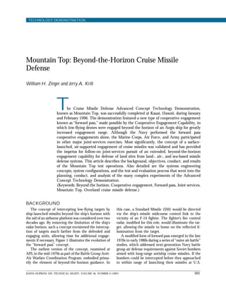
- 7. JOHNS HOPKINS APL TECHNICAL DIGEST, VOLUME 18, NUMBER 4 (1997) 507 MOUNTAIN TOP: BEYOND-THE-HORIZON CRUISE MISSILE DEFENSE The Kokee Park Site A, situated 3800 ft above sea level, was an abandoned NASA installation. The Navy had to establish appropriate electrical services, repair and upgrade the laboratory facilities, and erect special towers to support the radars and CEC (Fig. 3), while meeting the environmental standards of this famous state park. Kokee also served APL and E-Systems as the primary engineering data analysis site for the CEC network and as the base of operation for the radar agents, MIT, and the Naval Sea Systems Command. Aegis and SM-2 data analyses were performed by Lock- heed Martin and the Navy at Barking Sands. APL, in collaboration with the Navy, established data lines to the primary test conduct and control site at Barking Sands to make the composite CEC track data output available for test control. The 1700-ft-elevation Makaha Ridge site, equipped with the AN/SPS-48E (hereafter, SPS-48E) surveil- lance radar and IFF (information friend or foe), was integrated into the Kokee CEC system via fiber-optic lines. This enabled the elevated sites to more accurate- ly resemble the full avionics suite of the elevated fire control/surveillance aircraft concept, which would be expected to provide a multiple-target tracking and IFF capability. The integration scheme complemented the single-target tracking radar and fire control radar ele- ments at Kokee and provided for multiple mutual tar- gets with the SPY-1B radar of an Aegis cruiser for CEC precision gridlock (these and other defense units are described in the next section). To provide a ready surrogate “link” between CEC and the Army Patriot unit, Joint Tactical Information Distribution System (JTIDS) terminals were installed at both the Kokee and Barking Sands sites, i.e., at Kokee the JTIDS was indirectly connected to the CEC display interface via a device developed by the Naval Space and Air Warfare Command, and at Barking Sands the ter- minal was connected to an existing Patriot interface. The airport at Barking Sands supported a commercial helicopter equipped with APL-developed atmospheric sensors,3,4 the Captive Seeker Lear aircraft (discussed below), and the P-3 aircraft used in the Enhanced Scenarios. Both the Makaha Ridge site and an aerostat tethered at Barking Sands were equipped with special infrared sensors to provide insight into potential coop- erative, networked infrared systems for longer-range de- tection of low-flying targets. Before describing the actual test operations, the technical foundation upon which the Mountain Top results were based is described in the following section. TECHNICAL FOUNDATION System Elements The weapon system elements participating in the Mountain Top beyond-the-horizon ACTD (Set 1) are presented in Table 2; Table 3 lists additional elements participating in the Enhanced Scenarios (Set 2). The following paragraphs briefly describe the characteristics of the CEC-networked weapon system elements. CEC: Sensor and Fire Control Network As noted in the boxed insert, the CEC was developed to allow a net- work of air defense units to inte- grate their collective sensor mea- surement and weapons control data so as to operate as a single, distrib- uted air defense system. For the ACTD, two specially adapted CEC equipment sets were built, one for the Kokee surrogate aircraft site and the other for the USS Lake Erie (Aegis CG 70). The CEC electron- ics differed somewhat from the permanent ship sets installed on the USS Anzio and Cape St. George (Aegis CG 68 and 71, respectively) to reduce weight and facilitate housing in a shelter. A follow-on cruise missile defense (CMD) phase Figure 3. Kokee Park “surrogate” aircraft site A, at a 3800-ft elevation. In addition to providing the surrogate forward pass aircraft functions, test data evaluation of the site elements and the CEC was conducted here. The system elements are described in the text. RSTER roto-dome array CEC array antenna MK 74 fire control radar and illuminator area Kokee site A engineering test evaluation and surrogate avionics facility
- 8. W. H. ZINGER AND J. A. KRILL 508 JOHNS HOPKINS APL TECHNICAL DIGEST, VOLUME 18, NUMBER 4 (1997) Table 2. Major beyond-the-horizon test elements (Set 1). Element Type Function Radar surveillance Pulsed Doppler array Stationed at elevated sight to perform target technology experimental radar surveillance radar (RSTER) Mark 74 (MK 74) Tartar fire control radar Stationed at elevated site to provide precision target data and target illumination SPS-48E Terrier New-Threat-Upgrade Stationed at elevated site to provide three-dimensional radar surveillance and gridlock data CEC Cooperative engagement/ Networked radars and illumination to weapon sensor network control for composite track picture and cooperative engagement USS Lake Erie Aegis, CG 70 Provided engagement control and missile launch/guidance SM-2 Block IIIA Guided missile Responded in-flight to midcourse (instrumented) commands and performed semi-active homing and warhead fusing BQM-74 Drone Controlled from elevated sight; flown with characteristics of a low-altitude attacker Table 3. Major additional elements used in the Enhanced Scenarios (Set 2). Element Type Function USS Anzio and Cape St. George Aegis, CG 68 and 71 Varied depending on scenario, including (with CEC) data collection and cooperative SM-2 engagements Hawk Marine Corps anti-air Provided engagement control and missile weapon system launch/guidanceforHawkmissilefirings TPS-59 Hawk radar Provided elevated surveillance Aerostat Tethered, unmanned airship Supplied elevated digital communication relay for Hawk firings and infrared sensor test vehicle AWACS Air Force airborne warning Collected surveillace radar data and and control system reported tracks over JTIDS P-3 U.S. Customs Service surveil- Served as part of the CEC net with lance aircraft (with CEC) surveillance radar Patriot Army surface-to-air Collected radar data; reported missile system tracks over JTIDS BQM-74/-37 Target drones Served as SM-2 and Hawk firing scenario targets JTIDS Link 16 Tactical data link Provided command/control link F-15/F-16 Air Force and Air Served as scenario red and blue forces Reserve fighters Big Crow and Q-Lear Electronic warfare test aircraft Served as electronic warfare threats (jammers)
- 9. JOHNS HOPKINS APL TECHNICAL DIGEST, VOLUME 18, NUMBER 4 (1997) 509 MOUNTAIN TOP: BEYOND-THE-HORIZON CRUISE MISSILE DEFENSE is being planned, which will feature a next-generation preproduction E-2C version of the CEC equipment called the “common equipment set.” This set has iden- tical electronics for surface and air units, yet conforms to the more constrained airborne payload. Reference 1 discusses the differences between these versions. Functionally, the CEC for this demonstration was a derivative of the version used during 1994 develop- ment testing2 with the addition of hardware and soft- ware for interfacing with radar surveillance technology experimental radar (RSTER) and the Mark (MK) 74 tracking illuminator. RSTER: Advanced Airborne Surveillance Radar RSTER was developed for ARPA by MIT Lincoln Labs to evaluate experimental Doppler radar technol- ogies. For this demonstration, RSTER was installed at the Kokee site to provide the required horizon detec- tion range performance and was fitted with a prototype advanced E-2C phased array antenna in a “roto-dome” configuration. The system search and track software was also modified by MIT for the ACTD to significant- ly increase the update rate, so as to minimize track filter lag errors due to target maneuvers and to ensure earlier detection through shorter search frame times. Aegis: Air Defense and Combat System Aegis ships were the primary air defense forces in most Mountain Top scenarios. The Aegis air defense weapon system uses the multifunctional SPY-1B phased array radar to perform the search, track, and fire control functions. The CEC-integrated version of the Aegis weapon system that was a derivative of the Baseline 4 computer programs1 was used with minor modifications to meet ACTD requirements. This version had been demonstrated to enable the Aegis system to perform an SM-2 engagement on a target, even when the firing ship’s SPY-1B radar did not track the target, by using fire control radar data from another ship via CEC. This type of cooperative engagement, i.e., EOR, was de- scribed earlier in this article. Tartar MK 74: Surrogate Airborne Fire Control Tracking Radar and Illuminator The Aegis system with CEC had already been modified to accept remote fire control radar data from either another Aegis radar or from a fire control radar on Tartar New-Threat-Upgrade (NTU) ships that sup- port a different version of SM-2.1 For testing in 1994, the Tartar system had also been integrated with CEC and was able to meet the engagement range objectives of the management plan with remote data, serving as either a source or a firing unit.1 For this ACTD, the Tartar MK 74 missile fire control system installed at the Kokee site served as both the fire control radar source and the terminal homing illuminator for the Aegis SM- 2, in the same manner as it serves as both radar and illuminator on a Tartar ship for a Tartar configuration of SM-2. Modeling indicated that the MK 74 met the required fire control radar detection range and had sufficient illumination power for a modified SM-2 missile to achieve the intercept range well beyond the ship horizon, even if the ship was 25 nmi forward of the illuminator. Relatively minor changes were made to this element, mainly to make it compatible with RSTER cueing accuracy and with negative, look-down target elevation angles (owing to its mountain altitude relative to the horizon). Figure 3 shows the MK 74 system, RSTER, and CEC antenna as part of the Kokee site installation. SM-2 Block IIIA with Experimental Modifications The latest-generation SM-2 in the Fleet is the Block IIIA, which, like Block III, has exhibited a very high intercept success rate. As will be noted in the next section, a beyond-the-horizon geometry and an elevat- ed illuminator produce much greater sea reflection than seen in normal low-altitude engagements. There- fore, to reduce clutter interference, Hughes Aircraft modified the IIIA seeker by incorporating the “Plate 1 receiver upgrade” under development for the next- generation Block IV. The missiles were also furnished with a telemetry package to transmit terminal homing signals to determine intercept performance. Systems Engineering Approach The systems engineering process used to develop the distributed Navy forward pass weapon control network (consisting of Aegis/SM-2, CEC, and the mountaintop radars and illuminator) entailed all participating orga- nizations in extensive analysis, experimentation, and planning extending over a 30-month period. Figure 4 shows this process as it applied to Mountain Top. Be- cause of the diversity of program offices involved, each with their respective engineering teams, a systems en- gineering working group was formed under the coordi- nation of the CEC program to ensure that design and interface issues were identified and resolved as the prin- cipals proceeded to design, review, and document the networked system. Issues included the ship and missile launch safety zone requirements for the PMRF range, types of drones, availability of systems (such as the versions of SM, Aegis ship combat system, and moun- taintop illuminator), and the local geological features.
- 10. W. H. ZINGER AND J. A. KRILL 510 JOHNS HOPKINS APL TECHNICAL DIGEST, VOLUME 18, NUMBER 4 (1997) The primary system models and simulations that have been used through the years by the various programs were adapted to this effort. Because the models had been previously validated with test data and broadly used, the systems engineering team had much confidence in them. As will be discussed later in this article, test results were very close to the model predictions. Since CEC provided the means to effect the ACTD’s “distributed weapon system,” the role of APL’s Technical Direction Agent (TDA) extended to tech- nical coordination in carrying forward the netted sys- tems engineering process. Since the Laboratory is also the TDA for the SM-2 and Tartar NTU programs, and serves as technical advisor to the Aegis program as well, it was involved on both sides of the CEC interfaces. Analysis Analysis prior to the Mountain Top demonstration showed that • Sensorsandfirecontrolcouldprovideadequaterange performanceagainstthespectrumofatmosphericand sea conditions experienced around Kauai. • CEC network and missile error budgets would permit midcourse guidance with acceptable errors for a suc- cessful terminal homing phase. • Missile seeker pointing errors at the start of terminal acquisition were sufficiently small to support target acquisition. • The Block IIIA version of SM-2 possessed sufficient kinematics to support stable flight and terminal con- trol at the ranges and altitudes of interest. • The Block IIIA would be able to acquire and track a drone-sized target in the expected sea clutter back- ground if modified with the Plate 1 upgrade to sup- press clutter interference. Missile Captive Seeker Critical Experiments In the course of the SM development program, APL had performed critical Captive Seeker5 experiments for ACTD management plan top-level requirements Interface specifications Functional/performance allocations Critical experiments and modeling Fabrication/modification Integration tests Site and preparatory tests Formal ACTD tests Figure 4. The systems engineering process as applied to the Mountain Top ACTD, beginning with the concept and requirements definition, proceeding through requirements allocation to the elemental level, and finally to testing from the smallest elements up to the fully networked composite system. APL provided leadership in modeling, requirements definition and allocation, interface specifications, critical experiments, site risk reduction scenarios, site subsystem checkout and verification, and test conduct. Shown in the formal ACTD test inset, from right to left, are APL’s Test Conductor, Art Jeyes, sitting beside the CEC and Mountain Top Program Manager, Michael O’Driscoll, and RADM Timothy Hood, the Program Executive Officer for Theater Air Defense.
- 11. JOHNS HOPKINS APL TECHNICAL DIGEST, VOLUME 18, NUMBER 4 (1997) 511 MOUNTAIN TOP: BEYOND-THE-HORIZON CRUISE MISSILE DEFENSE a variety of sea- and land-clutter conditions to deter- mine the effects on seeker performance against low- flying targets. These experiments showed that, based on Mountain Top geometry, steeper illumination inci- dence angle to the sea, longer range, higher surface reflection, and different Doppler characteristics, the missile receiver would require special filtering com- pared with a conventional engagement. The Plate 1 upgrade had already been developed for the longer- range Block IV missile, and performance modeling indicated that it would also suffice to allow the Block IIIA seeker to distinguish the illumination reflection from the target relative to that from the sea surface for the Mountain Top geometry. However, only limited experimental data existed to support this conclusion. To capture the seasonal sea and atmospheric char- acteristics to be encountered, the Captive Seeker experiment was conducted about a year before the ACTD. Another Captive Seeker test series was also performed for the actual engagement geometries and targets several months before the firing events. Both sets of test results confirmed that Block IIIA, modified with the Plate 1 clutter filter, would be effective under Mountain Top conditions. Radar Experiments The foregoing analysis and systems engineering ef- forts were augmented by risk reduction assessments and other critical experiments for key aspects of the dem- onstration, e.g., • Theacquisition,track,andilluminatorpowerdensity of the MK 74 system were examined for the geometry of each of the planned beyond-the-horizon en- gagement scenarios using the Captive Seeker system against drones. • TheacquisitionandtrackperformanceoftheRSTER radar was tested for the geometry of each planned engagement. • The modifications required to the Aegis combat system were analyzed, defined, and then tested at the Aegis combat system engineering development site. Test and Evaluation Process Test Engineering As a complement to the systems engineering pro- cess, a test and evaluation working group was formed early in the Mountain Top preparation effort. The group worked out such issues as • Impact on engagement range due to range safety requirements • Selection of the Kauai mountain ridge with sufficient height to achieve required range to the target horizon • Hawaiian state park environmental requirements for visual, electromagnetic, and acoustic noise effects • PMRF requirements to provide drone control out to the required ranges (resulting in the development of a new long-range drone control system for this purpose) • Selection and preparations of the BQM-74 drones with the requisite characteristics Scenarios were defined in terms of inbound trajec- tories and engagement geometries in accordance with the systems engineering design, and were embodied in a series of test and evaluation planning documents (e.g., Mountain Top installation plan and installation documents, PMRF plan, requests for test assets, test plan and procedures, and data evaluation plan). The Navy Program Office directed APL to conduct the test series. Test Planning The next level of detailed preparations included scheduling site preparations, ship installations, test support assets, and test range services as well as assess- ing ship availability requirements for checkout, re- hearsal, and test. Testing began at the subsystem level, for example, starting with the SPY-1B computer pro- gram and the CEC processor modules, proceeding through interface tests, and finally testing the entire CEC network of systems (Fig. 4). These tests were performed at the sites of the design agents (see Table 1). Interface tests were generally performed between CEC and weapon system elements at the combat sys- tem test sites using APL-supplied wrap-around simula- tors. Finally, network-level tests were performed at PMRF. Key decision points for the higher-level events were formal test readiness and control panel reviews, missile firing scenario certification review, and a weap- on safety review. The final reviews were chaired by senior Navy officers. BEYOND-THE-HORIZON TESTS Phase 1: Navy Firing Tests The Navy tests consisted of a series of firing exer- cises by an Aegis ship (USS Lake Erie) against a low- flying drone (BQM-74 representing a simulated enemy target). Remote target radar data were used along with illumination by radars mounted on the Kokee site radar surrogate “aircraft.” The integration of the target data from the elevated site into composite fire control– quality tracks was accomplished by CEC. The test con- figuration is illustrated in Fig. 5, which represents the CMD concept shown in Fig. 2. Not shown is the SPS- 48E three-dimensional surveillance radar at the lower Makaha Ridge site that provides target identification
- 12. W. H. ZINGER AND J. A. KRILL 512 JOHNS HOPKINS APL TECHNICAL DIGEST, VOLUME 18, NUMBER 4 (1997) and data to enable CEC to precisely gridlock the system elements relative to one another. Test Sequence The sequence for each of the beyond-the-horizon firing events was as follows (also see Fig. 6): 1. The CEC established gridlock (precise relative sensor alignment and position of scenario elements) from area targets seen by both the land site and ship. CEC unitsatthelandsiteandshipperformed(independent but identical) composite tracking and identification from distributed radar and IFF data. 2. The BQM-74 drone was launched from the Barking Sands site, flown outbound for 80 nmi, turned in- bound, and descended to low altitude. Kokee site Aegis CG missile initialization and midcourse Aegis/SM-2 midcourse uplink/downlink Standard Missile MK 74 CEC Track/illuminate Search/cue Composite track development Barking Sands BQM-74 Patriot radar SPY-1B radar horizon Joint Tactical Informatiom Distribution System RSTER Figure 5. Conceptual representation of Mountain Top tests configured to represent the cruise missile defense concept depicted in Fig. 2. Figure 6. Representation of the sequence of the initial beyond- the-horizon engagement. The plan view indicates a low-elevation inbound drone approaching the Kokee site with a crossing target intercept by the ship-launched SM-2 (not drawn to scale). Niihau Kauai Pacific Missile Range Facility USS Lake Erie Kokee Park Barking Sands Planned intercept point North/southrangerelativetoKokee East/west range relative to Kokee
- 13. JOHNS HOPKINS APL TECHNICAL DIGEST, VOLUME 18, NUMBER 4 (1997) 513 MOUNTAIN TOP: BEYOND-THE-HORIZON CRUISE MISSILE DEFENSE 3. RSTERdetectedthedroneandpassedmeasurement data to its land-site CEC. The CEC passed measure- ments to the ship. Both CEC units (land and ship) independently derived the track of the drone target. 4. Aegis commanded the drone to be engaged. From the engagement command, CEC cued MK 74 to acquire the target. Both CEC units performed composite tracking of the drone using RSTER and the more accurate MK 74 data. CEC provided target measure- ment data from the MK 74 to the ship. 5. TheshiplaunchedanSM-2missileatthetarget,then guidedSM-2viaitsmidcourselinktowithinterminal homing range using CEC target data for fire control. 6. The CEC commanded MK 74 to illuminate the target. The ship commanded the missile to begin homing. The missile intercepted the target. Test Results For the initial scenario event, the drone approached a fictitious target on the beach, where it was intercept- ed by the SM-2 well beyond the ship’s horizon and well prior to the target area. The missile not only passed within lethal range of the drone but scored a direct hit. Figure 7 shows the composite track picture created by an automated data reduction system based on CEC data collected at the Kokee site. This was the first-ever engagement of a low-altitude target beyond the firing ship’s horizon. The distributed missile control between the ship and mountain site had been comparable in intercept per- formance to the best that could be expected of conven- tional, ship-only engagements, yet at a range many times that possible by the cruiser against such a target without the elevated elements. Furthermore, the predicted SM-2 seeker characteristics, the detailed models of detection and track performance of the mountain sensors, and the simulated missile fly-out predictions were very close to actual event results. Another scenario event (Fig. 8) featured the drone flying toward the ship and crossing relative to the is- land mountaintop sensors. The missile made a success- ful intercept and damaged the target. Again, the inter- cept range was well beyond the firing ship’s horizon and very close to model predictions. The final forward pass scenario of this set of events entailed aligning the drone approach path with the ship and the mountain. Although the geometry was simpler (i.e., the drone was inbound and not crossing with regard to the ship and mountain site), detection and engagement presented a greater challenge because of predicted multipath propagation fading. However, the missile again successfully intercepted the target. The engagement range was close to the maximum that modeling indicated to be achievable for the test con- ditions and system elements used. This final test highlighted an important feature of the CEC design: When the ship first ordered an engage- ment, causing the CEC to cue the MK 74 fire control radar from RSTER data, the MK 74 could not acquire the target because of a (predicted) multipath fade at that range. The CEC unit on the mountain reported to the ship CEC that the required remote data could not be provided at that time. The ship operator, so alerted, ordered the engagement again, by which time the drone had flown out of the fade region, thereby enabling the MK 74 to acquire and support the successful intercept. These tests met and exceeded all objectives. All three low-flying targets were successfully intercepted at ranges well beyond those possible with a single ship. The tests demonstrated the technical feasibility of providing a Fleet-wide ability to defend inland targets against low-flying cruise missiles using special aircraft (or aerostat) systems to greatly extend each ship’s en- gagement horizon. SM-2 Intercept Kokee site A RSTER MK 74 Figure 7. Data reduction plot of tracks from the first beyond-the- horizon firing. The track histories of the drone and the intercepting missile are shown. The histories terminate at the intercept point where the missile impacts the drone. As the engagement is ordered by the ship, the MK 74 automatically is cued from the RSTER data and acquires the target. MK 74 data are used for missile guidance via the ship. RSTER MK 74 SM-2 Kokee site A Intercept Figure 8. Data reduction plot of tracks from the second beyond- the-horizon firing (see Fig. 7 caption).
- 14. W. H. ZINGER AND J. A. KRILL 514 JOHNS HOPKINS APL TECHNICAL DIGEST, VOLUME 18, NUMBER 4 (1997) Phase 2: Army Experiments The Army was unprepared as of 1996 to conduct firing tests comparable to those of the Navy. Their plan, therefore, called for simulated engagements and captive seeker experiments to test the potential of forward pass intercepts by a Patriot weapon system. Elements of the simulations and experiments were the Patriot PAC-3 weapon system located at Barking Sands (Fig. 5), a computer simulation of the missile, and the aircraft- mounted advanced Patriot Extended-Range Intercept Technology Missile (ERINT) captive seeker carried aboard a C-130 aircraft to simulate target engagements against low- to mid-altitude drones. For this phase, the CEC composite track data were transmitted from the Kokee site to the Patriot via a JTIDS communications link using a “link all-purpose workstation” interface unit to translate CEC messages to JTIDS format. From Patriot, the composite data were supplied to the simulation and linked to the captive ERINT seeker. These Army simulations were successful, demonstrat- ing that the target would have been intercepted in a high percentage of cases.6 For each ERINT seeker test, the Patriot unit was able to cue the captive seeker to acquire the target on the basis of CEC composite track data. ENHANCED SCENARIOS For Set 2 of the Mountain Top ACTD operations, Enhanced Scenarios, two additional CEC-equipped cruisers from the Atlantic Fleet and a CEC-equipped U.S. Customs Service P-3 aircraft were brought in to provide greater opportunities for joint, extended air defense experimentation. With participation by an Air Force AWACS test aircraft, a total of three Aegis ships equipped with CEC, a Marine Corps Hawk system (modified to accept fire control cues via CEC from Aegis and mountain sensors), the P-3, and an Army Patriot site, a truly all-service experiment under care- fully controlled test conditions was made possible. During this stage of Mountain Top tests, the Navy and APL worked closely to establish the test objectives and design and certify the scenarios, which were subse- quently agreed to by the other services. Those objec- tives aimed • To provide further risk reduction opportunities for the upcoming CEC initial operational capability (IOC), i.e., formal Fleet deployment, later that year • To provide an opportunity for further CEC data collection in support of new tactics development and new concepts • To afford an opportunity for joint-services participa- tioninalittoralsettingwithexplorationofsensorand weapons networking (via CEC) and command/ control networking (via JTIDS) Sequence of Operational Scenarios Again, the Enhanced Scenarios comprised three phases: 1. Arrival on the scene: Aegis ships—the Cape St. George, Lake Erie, and Anzio—and the Customs Service P-3 equipped with CEC arrived on the scene (Fig. 9a). The CEC network established a composite area picture. 2. Defense against shore-based attack: the Army’s Pa- triot battery and the Air Force’s AWACS joined operations (Fig. 9b). Simulated air attacks were launched against forces. 3. Jointlittoraloperations:Joint-serviceoperationswith participation of the Navy ships, P-3, Patriot, Hawk, AWACS, and fighters (Fig. 9c). Enemy jammers attacked nearly all radars. Phase 1: Arrival on the Scene This initial phase featured two experiments that were designed to provide data to support the development of Figure 9. Enhanced scenarios: (a) Phase 1, arrival on the scene; (b) phase 2, defense against shore-based attack; (c) phase 3, joint littoral operations. P-3 USS Lake Erie USS Anzio SPS-48E F-16s F-16s Radar sectors (a) Patriot Drones P-3 AWACS Jammer Silent shooter target (b) AWACS Patriot F-16s/15s F-15s or C-12s F-16s/15s F-16s P-3 Jammers USS Lake Erie USS Anzio Hawk TSP-59/ fire control (c) USS Cape St. George USS Cape St. George Kokee Kokee Kokee
- 15. JOHNS HOPKINS APL TECHNICAL DIGEST, VOLUME 18, NUMBER 4 (1997) 515 MOUNTAIN TOP: BEYOND-THE-HORIZON CRUISE MISSILE DEFENSE advanced CEC functions. The first experiment involved the three Aegis cruisers, the Kokee site, and the P-3 aircraft in the CEC network. Its objective was to collect data relevant to the ability of CEC to allow radar cov- erage coordination. In severe clutter or jamming or against difficult targets (e.g., future tactical ballistic missiles), units equipped with CEC may each elect to cover only certain sectors with their radars to cooper- atively manage available transmitter energy and retain appropriately short search frame times. These sectors may be coordinated via CEC. In that case, if a unit detects a target in its sector, the other ships’ radars may cue off the data, or one of the other ships may even engage the target using the detecting unit’s data (i.e., an EOR). The data collected in these tests indicated that the units were effectively positioned to uncover regions blocked by terrain. Thus, although several tracks were only held by certain units at a time (because of blockage, sectoring, etc.), CEC allowed all networked components to process the collection of radar measurement data from all other CEC units with accuracy comparable to or better than the sensors themselves. As tracks transi- tioned between sensors, composite track continuity (in terms of position, velocity, identification, and composite track number) was maintained. The second set of experiments in Phase 1 was per- formed to collect data for laboratory testing of a new capability that was introduced in CEC for its IOC that occurred later in 1996. This capability integrates radar passive angle (PAT) data from targets emitting radia- tion in the radar band into the CEC composite tracking process. The new algorithms associate PAT measure- ments with CEC track data and associate PAT data from two or more units to derive range and bearing as well as elevation angles as outputs of the CEC filter (analogous to passive range triangulation). A “deghost- ing” algorithm also acts to resolve multiple jammers to obtain a unique aircraft location of each or an indica- tion that insufficient data are available to do so. Con- firming previous analyses, the radar passive range com- posite track was of sufficient quality that it could support missile engagements over a wide range of emitting target positions relative to the tracking ships. This capability for missile engagements from passive composite track data is planned for future incorpora- tion into CEC and Aegis. Despite test curtailment due to extremely severe weather, some very useful data were collected, allowing laboratory evaluation of the real-time passive tracking process. The data supported both PAT-to-active track association and passive ranging, as shown in Fig. 10. The IOC package did, in fact, successfully field the new CEC passive range tracking capability. In addition, data col- lections from all units were obtained to support further CEC and JTIDS network architecture assessment. Passive only track Radiating aircraft 1 Passive/ active track Radiating aircraft 2 Active track Figure 10. Passive ranging scenario. Shown are the track histories from two separate aircraft emitting radiation in the radar band for which the cruisers each obtain a passive angle track (without the range dimension). The data collected from the passive ranging scenario were replayed through the next-generation Cooperative Engagement Processor tracker several weeks after the event to confirm the process for the subsequent CEC initial operational capability (IOC). The CEC IOC track filter used active (three- dimensional) and passive (two-dimensional) track measurement datatogeneratehighlyaccuratethree-dimensionalcompositetracks. Phase 2: Defense Against Shore-Based Attack These scenarios consisted of several simulated and actual missile engagements. The first event demonstrat- ed the ability of CEC to provide high-quality composite tracks in the presence of various forms of electronic countermeasures against the networked sensors. The second scenario demonstrated CEC’s ability to support the Navy’s “silent shooter” tactic. In this tac- tic, one or more ships are stationed at positions that give them good engagement coverage of regions where hostile missiles or aircraft might attempt to penetrate. These ships operate in an “emissions con- trol” state with radiating systems off (at least in the expected penetration sector). They are linked by the CEC network to ships with active radar located where they could only be reached by hostile forces if they flew through the area guarded by the silent units. A silent ship, knowing the enemy’s precise location via the CEC network, could launch an SM-2 missile to engage the target, without ever enabling radar search, using remote data from the network to direct midcourse guidance and target illumination. If the engagement could be completed before the firing ship could be detected, a very effective silent shooter capability would result. The simulated en- gagements by the “silent” ship in this scenario provid- ed valuable data for future system design and tactics development.
- 16. W. H. ZINGER AND J. A. KRILL 516 JOHNS HOPKINS APL TECHNICAL DIGEST, VOLUME 18, NUMBER 4 (1997) Two missile firing scenarios were also executed during this phase. To increase range safety margins for the multiple ships participating, drone targets operated at altitudes above those used in the beyond-the-hori- zon tests. Instrumented SM-2 Block III missiles were used. In one scenario, BQM-34 drones were flown simultaneously at two cruisers, with a third cruiser off to the side. The objectives of this scenario were two- fold: (1) to provide two simultaneous engagements on remote data with the same remote data source (for the first time), and (2) to collect data for a risk reduction evaluation of a new coordinated engagement algo- rithm known as “first launch” (invented by the Aegis prime contractor, Lockheed Martin, while under APL subcontract in the mid-1980s). The first launch process was incorporated in the CEC IOC package in 1996. When enabled by an operator, this feature allows the first ship to order an engagement to report over CEC, so that the other ship removes the target from its immediate engagement queue, thereby minimizing unwanted, redundant en- gagements. The test event culminated with successful launches and engagements by the Anzio and Cape St. George using remote data from the Lake Erie. The engagements were so well coordinated by the firing ships that the intercepts occurred nearly simulta- neously. Figure 11 is a snapshot of the CEC display of the event during the midcourse phase of the engagement. In a similar firing scenario, the Anzio engaged and successfully intercepted a pair of targets using re- mote data from the Lake Erie. This was the first occur- rence of multiple engagements by a firing ship using remote data and was scored as a success (Fig. 12). In all, there were five successful SM-2 Block III EOR firings. Figure 11. CEC snapshot of dual cooperative engagement events by two firing ships—the USS Anzio (CG 68) and Cape St. George (CG 71)—engaging drones using the USS Lake Erie (CG 70) SPY-1B remote data. The triangles are the drone targets. The CEC-equipped units are circles. The upper-half squares near the drones are SMs in flight.The dotted lines between CG 70 and the targets indicate that CG 70 is the source of fire control data. The solid lines between CG 68 and 71 and the drones indicate the target/ship engagement pairings. The thin solid lines indicate direct CEC connectivity among CEC units.
- 17. JOHNS HOPKINS APL TECHNICAL DIGEST, VOLUME 18, NUMBER 4 (1997) 517 MOUNTAIN TOP: BEYOND-THE-HORIZON CRUISE MISSILE DEFENSE Figure 12. CEC data reduction plot of dual drone cooperative engagements by a single ship. The track histories of the drones were obtained by the USS Lake Erie (CG 70), which was the source for dual engagements on remote data by the Anzio (CG 68). Phase 3: Joint Littoral Operations This final phase of the Enhanced Scenarios provided an opportunity for the CEC-equipped ships, P-3 air- craft, and the Kokee site to operate with joint elements in a common scenario. The Navy units were intercon- nected by the CEC and to the Army and Air Force by the JTIDS. The first all-services operations using a tactical Model 4 JTIDS network were conducted. AWACS radar data were collected in these operation- ally representative situations simultaneously with CEC network data as a basis for beginning development of requirements and a design concept for integration of AWACS into the CEC network. TPS-59 radar data were collected for the same purpose. Development work using these data has begun. The CEC network tracks of several “two-on-two” F-15/ 16 air combat operations were conducted. These composite tracks were formed by the radar and IFF equipment on the three Aegis cruisers and the P-3, with no loss of track identity or continuity, even though significant main-beam radar jamming was present. The primary scenario consisted of 12 fighters, half designated blue force and half red force, to conduct operations in concert with airborne electronic counter- measures against participating radars. It was first run with the CEC operating using a specially defined composite identification doctrine and CEC tracks reported over JTIDS only from the Kokee site JTIDS unit (others were in a receive-only con- dition) to represent the near-future CEC/JTIDS interoperability archi- tecture. This architecture will fea- ture CEC sensor-networked identi- fication doctrine in accordance with JTIDS-promulgated com- mand/control doctrine as well as JTIDS reporting of CEC composite tracks for greater track life and more consistent track number and identification correlation. Figure 13 is a data reduction plot of the event midway through the scenar- io. A second “without CEC” run of this same scenario allowed the units to operate the first truly joint JTIDS Link 16 protocols with the three cruisers, AWACS, and Patri- ot in the network. Also as part of this phase, the Hawk battery conducted live firings against drones. The scenario con- sisted of a BQM-74 drone with towed targets inbound toward the battery. For one firing, the compos- ite track data were supplied by CEC and relayed through the aerostat, mentioned earlier, using a single-channel ground-to-air military radio as a surrogate CEC Data Distribution System (see the boxed insert). The composite track consisted of sensor data from the three Aegis cruisers and the Kokee site. Figure 14 illustrates the configuration. All five Hawk engage- ments were successfully executed with either fire control radar cues from CEC or from the TPS-59 radar on Makaha Ridge (representing an elevated sensor). As part of the follow-on evaluation, collected TPS-59 data have since been processed through a CEC processor at APL and integrated into the composite track picture. Figure 15 is a CEC display snapshot of the composite track history for data collected during one of the Hawk missile firings. The resulting composite track picture, although not fully optimized to specification at that time, revealed the potential contribution of such a land-based radar to the Navy CEC network. From its elevated van- tage point, the TPS-59 provided radar data of a target not detected by the other CEC units as well as early detection of the drone launch from Barking Sands. The latter would have provided for automatic special acquisition of the target by one of the Aegis radars if the TPS-59 had actually been in the CEC network. These results were an initial step toward the integration of the TPS-59 radar and CEC, which was achieved in 1997. Jammer aircraft Outbound drones Inbound drones Missile track Kokee site ACG 68 CG 70 CG 71 AWACS track
- 18. W. H. ZINGER AND J. A. KRILL 518 JOHNS HOPKINS APL TECHNICAL DIGEST, VOLUME 18, NUMBER 4 (1997) Figure 13. CEC data reduction plot of a complex joint operations scenario. The composite track histories of the scenario are shown. Tracking and identification continuity were maintained throughout, and the CEC composite tracks were reported over JTIDS from the Kokee site. The colors in the track histories correspond to the colors of the CEC units indicating the portions of the track contrib- uted by each unit. Figure 14. Illustrated configuration of Aegis, CEC, aerostat, and Hawk. The Hawk high-powered illuminator/tracking radar was cued for successful engagements from the TPS-59 radar at the elevated Makaha site, as well as from the Aegis cruisers via CEC composite track. Three data paths are shown: blue, Aegis SPY composite CEC track via aerostat relay to cue Hawk fire control; yellow, cue of TPS radar and radar cue of Hawk fire control; red, direct cue of Hawk fire control. Results This portion of Mountain Top also met, and in several cases exceeded, its primary objectives. For ex- ample, it demonstrated the capability of CEC to sup- port the Navy’s silent shooter concept. In addition, two simultaneous ship engagements with SM-2 using re- mote data were successfully accomplished for the first time. The exercise provided an unprecedented oppor- tunity for concept exploration and data collection with five CEC-equipped units (three of which were Navy cruisers) operating with the participation of the Army, Marine Corps, and Air Force elements in a series of littoral scenarios. It supplied invaluable data for eval- uation of the potential integration of AWACS and the Marine Corps’ TPS-59 Hawk radar into the CEC network. SUMMARY Significance of Test Results The Mountain Top ACTD successfully demonstrat- ed the feasibility of the forward pass mode of target engagement, an approach conceived over 20 years ago to extend air defense capability beyond a ship’s horizon USAF AWACS and KC-135 tanker CG 68 CG 71 CG 70 Kokee site A F-16s (2) F-15s (4) Jammer Jammer Jammer Jammer P-3 CG 71 CG 68 Target TPS-59 CEC Kokee site CEC line Hawk launchers and fire control/ illuminators Aerostat relay of CEC data TPS-59 data fiber-optic line Makaha Ridge Hawk/CEC experimental fire control interface CEC network Aegis firm track of target
- 19. JOHNS HOPKINS APL TECHNICAL DIGEST, VOLUME 18, NUMBER 4 (1997) 519 MOUNTAIN TOP: BEYOND-THE-HORIZON CRUISE MISSILE DEFENSE Makaha Composite track with TPS-59 and Aegis SPY-1 contribution Composite track from TPS-59 data only CG 71 CG 68 TPS-59 Figure 15. CEC display with TPS-59 radar. A replay of collected TPS-59 radar measure- ments, conditioned to appear in the format of an SPS-48E radar, was run through a Cooperative Engagement Processor along with data collected simultaneously from CEC units. The lower track indicates that the TPS-59 had detected a target not detected by the cruisers. The track emerging and then turning toward the island is a target drone. The TPS- 59wasinapositiontodetecttheoutboundtargetbeforetheCapeSt.George(CG71)could do so. Had it been networked with the CEC, CG 71 could have provided data for the cruiser’s SPY-1B to acquire the drone prior to its own autonomous detection. with the aid of surveillance and target illumination air vehicles.7 In his message of congratulations, the late Chief of Naval Operations ADM Mike Boorda wrote ‘Outstanding’ is the only word to describe the re- sounding success you all achieved in both the advanced concept technology demonstration (ACTD) and en- hanced phases of the recently completed Mountain Top demonstrations. In discussing emerging technologies and warfighting capabilities, ‘revolutionary’ may be one of the most overused words in Washington. In this case, however, there is no question that you have set the stage for a revolutionary new way of fighting in the air defense arena. Because of your dedication and hard work, our task of quickly deploying this unprecedented warfighting capability has been made much easier. You were on time, on target, and on the money. Congratulations on a major success. All the best.8 The evolution of the concept and the ability of ex- isting Navy systems to be modified for such a demonstra- tion were the result of convergent mutual development of these systems, with APL as a key player. The fact that CEC, conceived by APL, was designed to enable such forms of cooperative engagement is due to the Labora- tory’s capability to preserve the technical vision over multiple generations. It may also be attributed to APL’s complementary roles in development of Navy air defense systems that enable it, in partnership with the Navy, to ensure that key synergistic features are present in these systems to facil- itate their technical advance in a balanced, focused, and mutually sup- porting manner. The potential of the land-attack CMD concept to protect U.S. and coalition forces in future conflicts is a compelling reason for further de- velopment of such capabilities by the joint services. The success of the Mountain Top exercises pro- vided a critical step toward this ob- jective by proving the integration concept and the potential perfor- mance amplification over individ- ual systems. These tests also further explored the foundations of weap- on and sensor networking (via CEC) and command/control net- working (via JTIDS) for joint-ser- vices CMD operations. The Future Since the Mountain Top be- yond-the-horizon firing events were successfully completed, dis- cussions of a follow-on have been intense. The definition of the follow-on CMD phase is being vigorously pursued by DoD, with all services recommending roles and next-phase approaches. As of this writing, a substantial test operation, even exceed- ing Set 1 in scale, is being discussed, with the intent to lead to a deployable prototype national resource. The various airborne platform options under consid- eration include a very large Army aerostat, a large Air Force aircraft, and a Navy carrier aircraft, possibly with unmanned aerial vehicles in a CEC subnet for en- hanced performance. Advanced Army, Navy, and Air Force missile variants are also being considered, and CEC and JTIDS are expected to be integrated as the sensor/weapons network and command/control net- work, respectively. The Enhanced Scenarios also have made an impact. First, they contributed to CEC meeting its congression- ally directed IOC schedule, with significant risk reduc- tion having been part of those scenarios. Second, the Marine Corps has begun integrating CEC into its Hawk system, and the Air Force and Army are considering prototype integrations of CEC into the AWACS test aircraft and missile batteries, respectively. All the ser- vices are further examining the use of CEC and JTIDS for CMD as well as tactical ballistic missile defense roles in a joint networking study.
- 20. W. H. ZINGER AND J. A. KRILL 520 JOHNS HOPKINS APL TECHNICAL DIGEST, VOLUME 18, NUMBER 4 (1997) THE AUTHORS JERRY A. KRILL received his B.S. and M.S. degrees from Michigan State University in 1973 and 1974, respectively, and a Ph.D. from the University of Maryland in 1978, all in electrical engineering. In 1973 he joined the Laboratory, where he is presently Supervisor of the Sensor and Weapon Control Engineering Branch of the Air Defense Systems Department. He is also a lecturer for The Johns Hopkins University Part-Time Graduate Program. Originally specializing in electromagnetic theory, Dr. Krill has published articles on electromagnetic scattering and guided wave technology and holds a number of U.S. patents. He has led systems engineering and critical experiments for the Navy’s Aegis and Battle Group Anti-Air Warfare Coordination programs. For 10 years he served as the APL System Engineer for the Cooperative Engagement Capability. Dr. Krill was recently named APL’s lead System Concept Engineer for the Navy Program Executive Office for Theater Air Defense. His e-mail address is Jerry.Krill@jhuapl.edu. WILLIAM H. ZINGER is a member of APL’s Principal Professional Staff and Associate Head of the Air Defense Systems Department. He obtained a B.S.E.E. from the University of Pennsylvania in 1961. Since joining APL in 1962, Mr. Zinger has worked on the design and testing of Fleet radars and related electronics. He has been associated with Aegis and its AN/SPY-1 radar since program inception. More recently, he served as the Technical Director of APL’s Cooperative Engagement Capability effort and led the Ship Self-Defense System effort within his organization. His e-mail address is William.Zinger@jhuapl.edu. REFERENCES 1“The Cooperative Engagement Capability,” Johns Hopkins APL Tech. Dig. 16(4), 377–396 (1995). 2Cruise Missile Defense Advanced Concept Technology Demonstration Phase I, Office of Naval Research (Mountain Top) ACTD Management Plan (Aug 1994). 3Dockery, G. D., and Konstanzer, G. C., “Recent Advances in Prediction of Tropospheric Propagation Using the Parabolic Equation,” Johns Hopkins APL Tech. Dig. 8(4), 404–412 (1987). 4Rowland, J. R., and Babin, S. M., “Fine-Scale Measurements of Microwave Refractivity Profiles with Helicopter and Low-Cost Rocket Probes,” Johns Hopkins APL Tech. Dig. 8(4), 413–417 (1987). 5Marcotte, F. J., and Hanson, J. M., “An Airborne Captive Seeker with Real- Time Analysis Capability,” Johns Hopkins APL Tech. Dig. 18(3), 422–431 (1997). 6Moore, D., 1996 National Fire Control Symposium, Eglin Air Force Base (Jul– Aug 1996). 7Blazar, E., “Firing Blind, Not Blindly,” Navy Times (29 Jan 1996). 8Boorda, M., “SUBJ/BRAVO ZULU//” Navy Message from CNO, N03210, MSGID/GENADMIN/CNO(N86)//Washington, DC (23 Mar 1996). ACKNOWLEDGMENTS: The authors wish to thank Alexander Kossiakoff, APL Director Emeritus, for his valued editorial guidance in preparing this manu- script. We also gratefully acknowledge the leadership provided by the Mountain Top ACTD and CEC program manager, Michael J. O’Driscoll, whose insight, team-building, issues resolution capabilities, and adherence to the systems engi- neering process were critical in making Mountain Top an unqualified success.