NASA's Boeing 757 Research Aircraft ARIES
•
0 likes•5 views

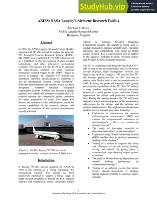
NASA acquired a Boeing 757 aircraft in 1994 to replace its aging Boeing 737 aircraft and continue aeronautical research. The 757 has undergone extensive modifications to transform it into a flying laboratory called ARIES. It features a Flight Deck Research Station and Transport Research System. ARIES conducts research flights to improve aviation safety, efficiency and capacity. Some examples of research include testing GPS landings, synthetic vision systems, and closely spaced approaches.

Recommended
Recommended
More Related Content
Similar to NASA's Boeing 757 Research Aircraft ARIES
Similar to NASA's Boeing 757 Research Aircraft ARIES (19)
More from Kimberly Pulley
More from Kimberly Pulley (20)
Recently uploaded
Recently uploaded (20)
NASA's Boeing 757 Research Aircraft ARIES
- 1. American Institute of Aeronautics and Astronautics 1 ARIES: NASA Langley’s Airborne Research Facility Michael S. Wusk NASA Langley Research Center Hampton, Virginia Abstract In 1994, the NASA Langley Research Center (LaRC) acquired a B-757-200 aircraft to replace the aging B- 737 Transport Systems Research Vehicle (TSRV). The TSRV was a modified B-737-100, which served as a trailblazer in the development of glass cockpit technologies and other innovative aeronautical concepts. The mission for the B-757 is to continue the three-decade tradition of civil transport technology research begun by the TSRV. Since its arrival at Langley, this standard 757 aircraft has undergone extensive modifications to transform it into an aeronautical research “flying laboratory”. With this transformation, the aircraft, which has been designated Airborne Research Integrated Experiments System (ARIES), has become a unique national asset which will continue to benefit the U.S. aviation industry and commercial airline customers for many generations to come. This paper will discuss the evolution of the modifications, detail the current capabilities of the research systems, and provide an overview of the research contributions already achieved. Figure 1: NASA's Boeing 757-200 aircraft is equipped to conduct a range of research flight tests. Introduction A Boeing 757-200 aircraft acquired by NASA in 1994 is now serving as a "flying laboratory" for aeronautical research. The aircraft has been extensively modified to support a broad range of flight research programs to benefit the U.S. aviation industry and commercial airline customers. Called ARIES, or Airborne Research Integrated Experiments System, the aircraft is being used to conduct research to increase aircraft safety, operating efficiency and compatibility with future air traffic control systems. It is a vital research tool in support of the agency's Airframe Systems, Aviation Safety, and Aviation Systems Capacity programs. The 757 is continuing work begun by the NASA 737- 100 in state-of-the-art technologies such as electronic cockpit displays, flight management systems and flight safety devices. Langley’s 737 was the first 737 off Boeing's production line in 1967 and was in service with NASA until it was decommissioned in 1997. Existing and projected research needs greatly exceeded the capabilities of the 737. The 757 offered a more modern airplane that utilized electronic systems to a much greater extent, and more closely represented the current and projected commercial fleet. During the coming decades, the 757 will better support research and development of the aeronautical sub-systems for the airlines and the airframe and systems manufacturers. The airplane has already been used for several research programs, including: • Flight-tests to characterize the internal electromagnetic environment (EME) and validate the computational assessment of electromagnetic effects in commercial transport aircraft.4 • The study of jet-engine contrails to determine their effects on the atmosphere5 . • Flight-tests using Global Positioning System (GPS) satellite data to perform automated landings of the airplane.6 • Testing of a system to improve the safety and efficiency of aircraft during landing, taxiing and takeoff by giving pilots a computerized map showing airport ground operations.7 • The study of Winter Runway Operations and aircraft braking performance on contaminated runways. 8 • Testing of an airborne system that allows closely spaced approaches to landings during reduced visibility to increase airport capacity. 9
- 2. American Institute of Aeronautics and Astronautics 2 • Evaluation of systems that would provide pilots with better strategic and tactical weather information while in flight. 10 • Flight evaluations of integrated synthetic vision systems. 11 Future research will continue to focus on technologies to improve air safety, efficiency and performance. History NASA Langley Research Center operated a B-737- 100 for over twenty-five years as a “flying laboratory”1 . The aircraft was the prototype 737 produced by Boeing in 1967. After Boeing completed the certification testing with the aircraft, it was reconfigured with a research system, including an operational aft research flight deck, and delivered to Langley. The aft flight deck allowed for safe and efficient testing of advanced cockpit displays and integration of emerging navigation, communication, and flight guidance and control technologies. Over the next several decades it completed several thousand hours of research flight time, testing out many of the concepts and technologies that exist in today’s modern civil transport aircraft. During the 737’s service at Langley, vital experience was gained in the integration, modification, and operation of this highly complex research facility. This would become an important factor in the development of a replacement aircraft. Figure 2: NASA’s First Flying Laboratory, the Boeing 737 In the early 1990’s it became evident that the emerging research demands and evolving programmatic focuses were starting to overtake the aging B-737. A search was begun for a replacement aircraft that would meet these growing demands and provide an able research platform to carry forward the research effort well into the new millennium. The soon-to-be NASA B-757 was located after an exhaustive analysis of the projected needs and an extensive survey of the jet airliner market. The candidate aircraft was the second 757 built and the first one produced that was sold to an airline. It is powered by two Rolls Royce RB211-535E4 turbofan jet engines with each engine generating 40,100 lbs. of thrust. The maximum take-off weight is 251,000 lbs. The aircraft’s max cruise is .86 Mach and it has a service ceiling of 42,000 ft. Figure 3: B-757 dimensions Boeing used this number two aircraft during the FAA certification testing. The FAA certified the 757 class of jet airliners on December 21, 1982, after 1,380 hours of flight-testing over a 10-month period. First delivery of a 757-200 took place December 22, 1982, to launch customer, Eastern Airlines. Eastern placed the aircraft into service January 1, 1983. This digitally equipped transport, designated N501EA, was flown by the airline until it’s bankruptcy in 1991. The aircraft was mothballed at McCarran International Airport in Las Vegas, Nevada until NASA finally obtained it from the Eastern Airline bankruptcy estate. Langley took possession of the $24-million aircraft March 23, 1994.2 Figure 4: NASA 557 after the purchase from Eastern, before changing to the NASA color scheme. After undergoing a thorough inspection and completion of scheduled heavy maintenance checks the aircraft was delivered to Langley on May 19, 1994. Initial familiarization flights were conducted and some minor modifications were begun which
- 3. American Institute of Aeronautics and Astronautics 3 would allow the completion of the Electromagnetic Environment experiment.4 Following the completion of these inaugural flight tests, the momentous task of reconfiguring the aircraft into its research configuration was begun in earnest. Whereas the B- 737 came to Langley already configured as a functioning test facility, many factors dictated that the B-757 would undergo its metamorphosis at Langley, completed by Langley civil servant and contractor staff. The experience gained over the years of operations with the B-737 provided a wealth of corporate knowledge and an extremely capable workforce to carry out the task. Regardless of these invaluable resources, the task at hand would be a monumental one requiring the efforts of many people and organizations, including extensive technical inputs from Boeing and many of their subsystem suppliers. Over the next several years, through multiple phases, the aircraft continued its evolution into a functioning flight test facility. It was during this time, in December 1998, that the aircraft was officially given the name ARIES, helping to further identify its unique role as a contributing entity in the field of aviation research. Sim-to-Flight Concept Even before its arrival at Langley, ARIES had been envisioned as an integral part of the Transport Research Facilities (TRF). The TRF is a set of tools used in a simulation-to-flight concept. This concept incorporates common software, hardware, and processes for both ground-based flight simulators and the B-757, providing Government and industry with an efficient way to develop and test new technology concepts to enhance the capacity, safety, and operational needs of the ever-changing national airspace system3 . These facilities enable a smooth continuous flow of the research from simulation to actual flight test. Three major facilities are used in the simulation-to- flight concept. The first is the Cockpit Motion Fa cility (CMF), a multiple -cab, fixed- and motion- based flight simulation laboratory that contains the Integration Flight Deck (IFD) simulator cab, the Research Flight Deck (RFD) simulator cab, and the Research System Integration Laboratory (RSIL). The IFD cab closely resembles the 757 forward flight deck or cockpit and is used in support of flight- testing on the ARIES and for aircraft systems integration studies. The RFD cab is an advanced subsonic transport flight deck used for full-crew- workload and full-aircraft-systems integration development and tests by the research community. The RSIL is a ground-based laboratory version of the ARIES on-board research system (described below) and is used for the integration of key hardware and software systems required for simulation. The second major facility is the Flight System Integration Laboratory (FSIL), a flight-testing counterpart to the RSIL. The FSIL is used for the aircraft integration and preflight validation of key hardware and software systems destined for ARIES. The third facility is the 757. ARIES currently features an on-board research system called Transport Research System (TRS) and the Flight Deck Research Station (FDRS), both of which are described later in detail. ARIES Concept Overview One of the attributes that made the B-737 such a powerful research tool was the research or Aft Flight Deck (AFD) located in the cabin area of the aircraft. This allowed a great majority of the research work to be accomplished in the AFD while still maintaining a sterile two-crew safety cockpit up front, in the Forward Flight Deck (FFD). In retiring the B-737, Langley’s plan for the B-757 has always included the integration and installation of an AFD onto the aircraft. Resource and budgetary constraints have dictated that a delayed phased approach be used to achieve this full-up research system implementation. Initial modifications to the B-757 cabin and cockpit have been focused at the establishment of the basic experimental infrastructure, called the Transport Research System. The TRS is comprised of the research computers and data collection systems used to support the experiments and tests. This hardware is distributed throughout the cabin, cockpit, and cargo hold areas of the aircraft at both manned and unmanned pallet stations. Major modifications completed in support of the TRS included installation of cooling ducts and distribution of ship’s power to each pallet location, and the installation of overhead cable trays in the cabin to accommodate data signal wiring. Pallet configurations and cabin layouts have changed as the aircraft modifications have progressed to meet the intermediate research needs, but even with the achievement of the current Coupled Baseline configuration, the system maintains a great deal of designed-in flexibility. Several of the pallet locations are reserved for project-specific pallet installations. The modification and integration of project specific research equipment is the quintessential goal of the aircraft and the TRS. Many of the evolving research efforts targeted to fly on ARIES require a real-world, out-the-window
- 4. American Institute of Aeronautics and Astronautics 4 view, or the ability to fully control the aircraft through any given phase of flight including take-off, landing roll-out and taxi. Even with the eventual AFD, the left seat of the forward flight deck is the only location that allows both. The concept of the Flight Deck Research Station (FDRS) was developed to accommodate these research requirements, yet maintain the normal utility of the aircraft, and protect the level of safety and oversight needed to conduct viable research operations. The FDRS is essentially a reconfiguration of the left side of the forward flight deck for test subjects to evaluate flight systems and operational procedures. As part of this concept, several modifications and operational controls have been implemented on the aircraft and are discussed below in more detail. The aircraft has undergone several distinct phases in reaching its current configuration. In order to continue to advance the research programs, modification phases have been interspersed with periods of research operations. The aircraft achieved an operational Transport Research System (TRS) in June 1997. The initial TRS capabilities allowed the completion of the Low Visibility Landing and Surface Operations (LVLASO) experiment in July and August of 1997. Completion of the Uncoupled Baseline TRS was accomplished in December 1998, allowing the display of experimental guidance to the FDRS. Following this, the aircraft completed the Wint er Runway Operations research in February 1999. The third major phase of modification for the TRS resulted in the current Coupled Baseline configuration. The Coupled Baseline allows for the aircraft to be coupled to and flown using experimental guidance. The first research program to make use of the Coupled Baseline was the Airborne Information for Lateral Spacing (AILS) flights during August 1999. During the aircraft’s transformation a majority of the modifications were completed by NASA civil servant and contractor personnel at LaRC. Several major structural modifications have been completed during scheduled heavy maintenance by contract facilities. The upcoming integration of the aft flight deck represents the final stage of the currently planned Baseline modifications. This installation, in combination with multiple systems upgrades, will require some rearrangement of the Baseline pallet locations as shown in this paper, but will retain or enhance all the existing capabilities. At the time of this writing, this effort is in the final design reviews and dedicated installation efforts are scheduled to begin in summer 2003. ARIES Coupled Baseline Configuration The cabin layout for the current Coupled Baseline configuration is show in Figure 5. The two main elements are the Flight Deck Research Station and the Transport Research System. The following sections detail each of these elements respectively. Figure 5: ARIES Baseline Cabin Layout Flight Deck Research Station (FDRS) With the Coupled Baseline configuration, the FFD’s left side primary flight display (PFD), navigation display (ND), and control display unit (CDU) can be replaced with research units that can be driven by experimental inputs from the Onyx computer. An experimental head up display (HUD), shown in Figure 7, has also been installed, providing another method of displaying experimental displays to an evaluation pilot. Additionally, the experimental system can provide inputs to the ship’s flight control computers, thus allowing automatic flight, including coupled autolands. Whether flown manually or coupled, the FDRS provides an evaluation pilot the ability to assess the desired research concepts, be they advanced displays, cockpit procedures, or aircraft performance. Figure 6: The 757 features a Flight Deck Research Station on the left, or captain's, side of the cockpit.
- 5. American Institute of Aeronautics and Astronautics 5 To ensure the ability of the right seat safety pilot to adequately protect the aircraft from undesired events, several standby instruments have been added to the instrument panel. (Most of these modifications were driven by the basic design philosophy of the B-757, where systems failure modes are all based on ensuring sufficient control for the left seat.) In addition the center isle stand has been reconfigured for the installation of an additional CDU, allowing for a second safety pilot to sit in the middle jump seat and be able to provide input into either the ship’s or the research navigation system. A fourth jump seat behind the right pilot seat provides seating for a researcher or observer. Figure 7: The FDRS experimental HUD Transport Research System (TRS) Fourteen test pallets/research workstations are in the baseline layout as shown in Figure 5. Others are added depending on research needs. There are twenty available pallet locations. Pallet stations are sequentially numbered by location, starting with the odd numbered pallets on the port side of the aircraft and the even numbered pallets on the starboard side. 1. Flight Systems Interface 2. Flight Management 6. Onyx Computer 7. Experimental Power Distribution 7A. Wire Integration Unit 8. Onyx Operator 9. I/O Concentrator 10. Video #1 (Video/Test Director) 11. Data Acquisition System (DAS) 12. Data Processing & Display Station (DPDS) 13. Video #3 (Video Routing Switch) 14. Video #2 (Video Recording) 15 Technology Transfer Area 1 (TTA1) 16 Technology Transfer Area 2 (TTA2) Stations 3, 4, 18, and 19 have been used for individual project pallet installations at various times. The cabin area of stations 3 and 4 has been designed for the eventual installation of an aft research flight deck. Standard audio, video and time functions exist at all manned pallet locations. Each of these pallets has an audio panel that provides the pallet occupants with the ability for two-way communications over any of the four intercoms and two of the four radio sources. The remaining two radios can be monitored by anyone, but only the flight deck crew is able to transmit. Each manned pallet also contains two 8" monitors that allow the pallet operators to select and monitor video images for enhanced situational awareness. Additionally, each pallet has an electronic time display driven by GPS-provided time code and a discrete event marker button that can be used to mark events on the data recording. Pallet #1 - Flight Systems Interface This pallet provides flight controls systems, thrust management systems, and the Pilot Selection Panel (PSP) monitoring. (The PSP is located in the flight deck and is the switch that selects between the standard ship’s control and the experimental control.) This pallet’s systems provide the FDRS experimental displays (PFD and ND) and Experimental Display Control Panel (EDCP) with power and setup control, as well as providing the HUD power, and signal conversion control and mixing. This station will play a major role in the integration and operation of the proposed AFD flight controls interface unit (FCIU). A secondary location for the aircraft’s Crew Chief, who would normally fly in the cockpit, is also provided at this pallet. During certain types of operations where a third safety pilot or research observer is required in the flight deck, the Crew Chief can be repositioned to the number one pallet where he has appropriate communications and monitoring capability. Pallet #2 - Flight Management Operators at this pallet oversee and manipulate the experimental Flight Management and Navigation systems. The pallet houses the experimental Flight Management Computer (FMC) and a second experimental CDU, as well as two Ashtech GPS receivers, and a prototype WAAS GPS receiver, any of which can be used to provide positional information to the experimental system. The pallet also controls three differential GPS (DGPS) datalink radios that can also be used to transmit or receive a pseudo- Automatic Dependent Surveillance-Broadcast (ADS-B) signal.
- 6. American Institute of Aeronautics and Astronautics 6 Pallet #6 - Onyx Computer This is the primary research computer on the aircraft. It drives the research displays and serves as the experimental Flight Management System (FMS) and/or the Flight Control Computer (FCC). The computer is a Silicon Graphics Inc. Onyx mainframe that has been specially re-housed and flight hardened. It has eight Computer Processing Unit’s (CPU’s) @ 200 MHz each and three graphic pipes capable of driving 18 displays at 1024x768x60hz. The computer draws 7kva power and requires 850 cubic feet per minute cooling air at 40 degrees Fahrenheit. Pallet #7 - Experimental Power Distribution This pallet is the interface between the aircraft electrical system generators and the experimental system. It controls the distribution of electrical power to the individual research system pallets and components through switches and circuit breakers located on the pallet. Experimental system power can be disconnected with an emergency shutdown switch located in the cockpit. Status of the research system electrical loading can be monitored using the panel meters and analyzers located within the pallet. The research system receives power inputs from each of the two engine generators (90 kva), auxiliary power unit (90 kva), and external power sources. Research equipment located in the forward cargo bay isolates 28 volts DC and 115 VAC, 60 Hz from the 115V AC 400 Hz bus generators. The research electrical system then distributes power via two power buses to each pallet station. Each research pallet station is interfaced to the research power buses through a local power sub-panel to distribute power on that pallet. All research power wiring is distributed to the pallets under the cabin floor to isolate it from research signal/data wiring that is routed in the overhead cable trays. Pallet #7A - Wire Integration Unit This unmanned pallet is the central wiring point for all signals used by the experimental system. Its patch panel configuration allows for relatively easy reconfiguration of multiple wire integration unit’s (WIU) sub-chassis for patching of signals to various pallets Pallet #8 - Onyx Operator The Onyx Operator station serves to monitor and control the Onyx computer. Operators start, monitor, and stop the research software running in the Onyx computer. This software typically runs the experimental displays and may also run any experimental algorithms or calculations required by the research. Pallet #9 - I/O Concentrator The I/O Concentrator pallet is the primary signal concentration point for the aircraft’s subsystems ARINC 429 data busses; 757 research sensors, research computer, Data Acquisition Systems (DAS), and other experimental system analog, digital, synchro and ARINC 429 signals. Utilizing a suite of VME cards and a 133 MHz MCP604 PowerPC processor, the pallet converts the above signal information to and from the SCRAMNet (Shared Common Random Access Memory Network) protocol that is used when transmitting data over the research system's fiber optic network ring. The SCRAMNet maximum throughput is 16 MB/sec. The pallet houses a quad switch junction box that forms the research system's fiber optic network ring. In addition, it provides high-fidelity IRIG-B time to the research system by utilizing a Time Frequency Processor (TFP) card whose internal oscillator is trained by signals from a GPS receiver Pallet #10 - Video #1/Test Director This pallet serves a dual role. It provides the primary monitoring and control station for the entire video subsystem (total of 3 pallets). In addition, it serves as the Flight Test Director station, providing the Test Director with communications capabilities and enhanced situational awareness with a total of eleven video monitors and a computer for data monitoring and GPS-driven positional display. The Test Director has a separate communications panel to allow independent communications on any available radio and intercom channel. The panel also includes a
- 7. American Institute of Aeronautics and Astronautics 7 tunable VHF radio (w/enable switch which allows any aft cabin stations to transmit via this VHF), and a public address handset for intra-aircraft announcements. As the video system control, the pallet uses nine monitors for verifying recorded images and two feedback monitors capable of selecting any of the four camera and four computer generated video sources. The pallet also houses camera control units for the four camera sources, the tail camera heater and controller, and a video selector switch that allows any of the audio sources onboard to be recorded on any of the video recordings. Pallet # 11 - Data Acquisition System (DAS) The DAS provides the data acquisition and storage of aircraft parameters from analog sensors, SCRAMNet fiber optic link, and the aircraft 429 busses. A setup computer is used for system setup, control, and monitoring. The heart of the DAS is the Advanced Airborne Test Instrumentation System (AATIS) pulse coded modulation (PCM) system. The AATIS has the capability to monitor 96 analog data channels and 192 discrete inputs. Direct connection to analog sensors is via the wire interface unit (WIU) and it’s associated signal-conditioning integrated circuitry. The DAS is connected to the aircraft 429 busses via a custom built 429 interface to the Advanced Airborne Test Instrumentation System (AATIS). The system is currently configured to record 1,000 aircraft parameters to magnetic tape using a Mars II tape recorder. Parameters can be recorded at a bit rate of 555,555 bits/second for 20 hours at sampling rates of 200, 50, 25, 12.5 and 6.25 Hz. The system is connected to the research system via SCRAMNet+ fiber optic link. Pallet #12 - Data Processing & Display Station (DPDS) The DPDS takes serial PCM data, processed and recorded by DAS, and converts any of 1,000 data parameters to engineering units (i.e., altitude in feet) for display to a researcher at the DPDS pallet in real-time. The system provides various easily configured display options, including plots, tabular data, time histories, and many different graphical formats. The display can be driven by real-time data, or used to play back previously recorded data. The DPDS can record as many as 500 parameters per second on an optical disk. The files can be moved to a floppy disk for later use by an experimenter or it may be sent to any device on the aircraft LAN. Once on the ground, the files may be transcribed to a CD for permanent storage. The system controller is a Force Computer 68040 processor installed in a VME chassis running VxWorks. Pallet #13 - Video #2 This is the primary video pallet for recording the video sources and for scan converting the signals into the correct output format. The system is capable of recording all of the video sources and contains a playback feature on VCR #1 for playing back video onboard the aircraft. The pallet contains 8 Super VHS video recorders, 4 YEM scan converters for converting the computer-generated sources, and 4 SONY scan converters for converting the video sources to the correct format for telemetry. Pallet #14 - Video #3 The Video three pallet provides switching for the video subsystem and recording of all audio sources. Two RM5000 routing switch matrices provide the ability to switch the appropriate video sources throughout the aircraft Diagnostic and troubleshooting equipment as well as multiple video distribution amplifiers for duplicating various video sources reside on this unmanned pallet. A Stancil audio recorder continuously records all audio sources, including the cockpit voice audio. Pallets #15 & 16 - Technology Transfer Area (TTA) #1, #2 This area allows researchers to accommodate up to 18 onboard observers, and provides them with the appropriate information to facilitate the real- time transference of technological knowledge during various flight tests. Each pallet has a 20" flat-panel display that can be configured to display the desired research images. Additionally, two 8" monitors
- 8. American Institute of Aeronautics and Astronautics 8 located on each pallet allows the monitoring of additional images. Audio speakers are utilized during onboard playback from VCR #1. These provide an audible source for demonstrations in the TTA. The TTA area also provides space for additional research pallet locations. ARIES’s Accomplishments Since ARIES was purchased in 1994 the aircraft has completed a variety of research efforts, most of which have been focused at furthering the efficiency, effectiveness, and safety of civil transport aviation. These studies have helped develop the technology that will enable the aviation industry to reach the national goal, set by President Clinton, of reducing the fatal aircraft accident rate by 80% in ten years and 90% in 25 years. A discussion of ARIES’ involvement in some of these programs follows. High Intensity Radiated Field Sources - (HIRF) 4 In February 1995, the NASA LARC conducted a series of aircraft tests aimed at characterizing the electromagnetic environment (EME) in and around a Boeing 757 airliner. As the complexity and criticality of the functions performed by the on-board electronics increases, so does concern about the vulnerability of these systems to electromagnetic interference (EMI). Sources of EMI that are of particular concern are man-made radio frequency (RF) sources generated external to the aircraft, such as radar and radio transmitters. These potential sources of EMI are collectively known as HIRF or High Intensity Radiated Field sources. During the EME flight test, measurements were made of the electromagnetic energy coupled into the aircraft and the signals induced on select structures as the aircraft was flown past known RF transmitters. The aircraft was instrumented with an array of sensors positioned to study the electromagnetic coupling characteristics and shielding effectiveness of the aircraft’s three main compartments; the flight deck, the avionics bay, and the passenger cabin. ARIES flew a total of 56 data runs against four RF sources. Predetermined flight profiles were flown to ensure that electromagnetic energy impinged upon the aircraft fuselage at various angles of incidence. The flight test provided data used to validate computational techniques for the assessment of electromagnetic effects in commercial transport aircraft. Such knowledge will improve the design process, resulting in more robust and cost effective designs. Low Visibility Landing and Surface Operations (LVLASO) and Runway Incursion Prevention System (RIPS) 7 A main focus of the research conducted at Langley is the investigation of technology that will improve the safety and efficiency of aircraft movements on the surface during the operational phases of landing rollout, turn-off, inbound taxi and outbound taxi. In poor visibility, at night, or at unfamiliar airports, operating safely on the airport surface at rates equal (or better) to those in clear weather requires that both pilots and controllers be provided with supplemental information about the state of the airport and relevant traffic. It is hoped that by providing supplemental guidance and situational awareness information to both pilots and controllers, safety margins will be increased and operations can be maintained at Visual Meteorological Conditions (VMC) capacities, regardless of actual visibility conditions. Initially conducted as part of the Low Visibility Landing and Surface Operations (LVLASO) program, this effort has evolved into what is now called the Runway Incursion Prevention System (RIPS). The change in name represents a programmatic evolution from a joint research project working capacity issues to a national effort addressing a critical safety issue. Certainly the demands for air travel continue to grow, but reported surface incidents have continued to increase at an alarming rate. Hazardous runway incursions rates increased by more than 50 percent and at least five fatal airport surface accidents occurred from 1990- 1999. In 2000, 431 surface incidents were reported, an all-time high. Reduced visibility was a contributing factor in many of these accidents and incidents. Since 1996, ARIES has participated in a series of flight experiments and demonstrations supporting this effort. ARIES has performed flight and taxi operations for LVLASO at the Hartsfield Atlanta International Airport in 1997, and for RIPS at the Dallas-Ft. Worth Airport in 2000. To complete the LVLASO and RIPS testing, ARIES was equipped with experimental displays that were designed to provide flight crews with sufficient information to enable safe expedient surface operations in any weather condition down to a runway visual range (RVR) of 300 feet. In addition to flight deck displays and supporting equipment onboard the B-757, there were also ground-based components of the system that provided for ground controller inputs and the uplink of surveillance of airport surface movements. The prototype system consisted of several advanced technologies that made up an integrated
- 9. American Institute of Aeronautics and Astronautics 9 Figure 8: RIPS HUD and Electronic Map Displays communication, navigation, and surveillance (CNS) system. Airport Surface Detection Equipment-3 (ASDE-3) data was fused with other surveillance data and was provided to both the controller and the test aircraft. Various algorithms analyzed the potential for incursions and generated appropriate alerts. This specific implementation was designed to show whether the concept was both operationally and technically feasible. These technologies were tested using the ARIES aircraft with both NASA test pilots and commercial 757 captains acting as evaluation pilots. The integrated ground and airborne components resulted in a system that has the potential to significantly improve the safety and efficiency of airport surface movements, particularly as weather conditions deteriorate. Data resulting from these tests are being used to enhance the system's capabilities for future implementations and to develop and validate requirements for using these technologies in the future. Runway Winter Operations8 Runway water, ice or snow was a factor in more than 100 airplane accidents between 1958 and 1993. Most of those accidents involved fatalities. In support of the national effort to reduce the fatal aircraft accident rate, the NASA Langley Research Center partnered with Transport Canada and the FAA in a five-year winter runway friction measurement program. The on - going research effort uses instrumented aircraft, friction-measuring ground vehicles and test personnel from around the world. The major objectives of the Joint Winter Runway Friction Program include coordinating different ground vehicle friction measurements to develop a consistent friction scale for similar potentially hazardous runway conditions, and establishing reliable correlation between ground vehicle friction measurements and aircraft braking performance. Accomplishing these objectives would not only give airport operators a better way to evaluate runway friction and maintain acceptable operating conditions, but would also contribute to reducing traction-related aircraft accidents. Figure 9: NASA B757 makes a test run on a snowy runway in Michigan. Since testing started in January 1996, five instrumented aircraft, including the Langley 737 and 757, and 13 ground test vehicles have been evaluated at sites in Canada, the United States, and Norway, completing nearly 400 instrumented aircraft test runs and more than 8,000 ground vehicle runs. Tests have been performed on a variety of runway conditions, where researchers have taken manual measurements to monitor conditions before and after a test run series. From this substantial friction database, engineers have developed an international runway
- 10. American Institute of Aeronautics and Astronautics 10 friction index (IRFI) to standardize friction reporting from different devices and to minimize pilot difficulties in making critical takeoff and landing decisions. An IRFI methodology standard that defines procedure and accuracy requirements is under review for approval by an international committee. The overall results from this program will increase aircraft safety and the capacity of airports where winter conditions are severe. Some of the results and test procedures may also apply to highway safety. Airborne Information for Lateral Spacing (AILS) 9 In 1999 NASA and Honeywell collaborated on a joint effort to develop concepts, procedures, and supporting technology to safely enable closely spaced, independent, parallel approach operations. The Airborne Information for Lateral Spacing (AILS) system expanded on existing communication and navigation technology to allow planes to land safely in bad weather on parallel runways spaced as close as 2,500 feet. Currently, the minimum runway separation during low visibility is 4,300 feet, which means that some of the nation's biggest airports have to shut down one of their closely spaced runways when weather conditions deteriorate. Among the facilities AILS technology could impact are airports in Detroit, Seattle and Minneapolis. The NASA B-757 ARIES and a Honeywell Gulfstream IV (G-IV) were used in the flight test effort. Honeywell provided the airborne DGPS, ADS-B datalink, Traffic Alerting and Collision Avoidance System (TCAS) II w/AILS algorithms, and ground DGPS components. During the flight- testing, both aircraft would be set up on closely- spaced parallel approach paths when the Gulfstream would begin to “stray” off course toward the B-757. With the AILS system, the aircraft would "talk" to each other via the ADS-B. DGPS signals provided precise information about each plane's location. The AILS algorithms would monitor the intrusion and trigger multiple levels of alerts. Ultimately, if required, the system could initiate an automatically flown evasive maneuver. Validation flights were completed at the NASA Wallops Flight Facility and in-flight demonstrations of the system were completed at Minneapolis-St. Paul International Airport in November 1999 for FAA officials and other Government and industry representatives. The demonstrations showed that safe weather- independent operations with closely-spaced runways could be viable through the simultaneous use of the, the AILS alerting functions, and simple, consistent pilot procedures that included a basic emergency evasive maneuver. Fewer bad-weather delays would mean financial savings for the airline industry, more efficient airport operations, and travelers arriving at their destinations on schedule. Synthetic Vision11 Synthetic Vision System (SVS) research is being conducted as a potential mitigation to the number one aviation safety hazard, Controlled Flight Into Terrain (CFIT), and the growing safety problem of runway incursions. SVS utilizes integrated, high-resolution databases and photo-realistic display concepts to provide improved situational awareness and path control. Used in conjunction with integrity monitoring sensors such as radar or Forward-Looking Infra-Red (FLIR), Synthetic Vision Systems have the potential to provide substantial safety and performance benefits. Figure 10: SVS HUD image The ARIES aircraft has been a key player in the SVS work completed at the NASA LaRC. Photo-realistic concepts have been successfully flown at Dallas-Ft. Worth in 2000, and Eagle-Vail, Colorado in 2001. Using GPS positioning, the synthetic vision software creates a three-dimensional map of the surrounding terrain. As the aircraft’s position changes, this map changes accordingly, providing the pilot with an accurate, 3D, moving display in the cockpit. In addition to the terrain, runways, path guidance, and other aircraft can also be integrated into the display. Digitally superimposing aerial photographs gives the images a photo-realistic look. These images can be presented to the pilot on either a head down display (HDD) or a head up display (HUD). The monochromatic HUD uses outlines and shading to create the 3D terrain effect. Figure 10 is a HUD image showing the mountainous terrain around Eagle, Colorado.
- 11. American Institute of Aeronautics and Astronautics 11 Figure 11: SVS HDD image The HDD projects full color images, making the most of the photo quality. Figure 11 shows a similar image as displayed on the HDD. Note the image detail, including buildings and streets. Recent terrain database information has been compiled using images collected by the Shuttle Radar Topography Mission (SRTM) conducted in February 2000. With this increased database information and the ever-increasing computational power available, the ability of the technology is expected to grow substantially in the coming years. The benefits of SVS will undoubtedly be realized in the coming generations of aircraft, but the ability to retrofit Synthetic Vision Systems into current glass and non- glass cockpits is proving to be a viable alternative and will provide future safety and performance benefits to the existing fleet as well. Summary The NASA Langley Research Center operates a highly modified B-757 aircraft to further the Agencies aviation research objectives. The aircraft’s experimental system can be re-configured to accommodate a wide variety of advanced aerodynamic, airframe, and avionic systems testing. The aircraft is just one part of the integrated research process and facilities at Langley that allows researchers to take their concepts and programs easily from the simulator or laboratory straight to flight testing. Acknowledgements This paper is an overview of a variety of efforts conducted over the span of many years by a large number of individuals at the NASA Langley Research Center. As such, it is largely a compilation of works by a number of different writers. In putting this together the author would like to acknowledge the help and input of the researchers and engineers who were directly responsible for the various programs and systems. The collective goal was to document the evolution, capabilities, and operational record of this unique national asset. Special thanks to Kathy Barnstorff Randy Bailey Lucille Crittenden Stella Harrison Kevin Shelton Denise Jones Barbara Trippe Tom Yager References 1. Wallace, L., “Airborne Trailblazer”, NASA SP- 4216, 1994. 2. NASA LaRC Factsheet FS-1999-12-41-LaRC, December 1999. 3. Fisher, B., White, J., “New NASA Transport Research Facilities to Support Research Flight Operations in Present and Future ATC Environments”, AIAA-975641, Oct 1997. 4. Moeller, K., Dudley, K., Quach, C., and Koppen, S., “In-Flight Characterization of the Electromagnetic Environment inside and Airliner”, NASA TP-2001- 210831, March 2001. 5. Anderson, B.E., et al, “Airborne Observations of Aircraft Aerosol Emissions”, GRL Vol.25 #10, pg 1689-1692, May 1998. 6. Murphy, T., et al, “The Boeing/Industry GPS Landing System Flight Test Experiments”, Institute of Navigation National Technical Meeting, Jan 1996. 7. Jones, D. R.; Quach, C. C.; and Young, S. D., “Runway Incursion Prevention System (RIPS): Demonstration and Testing at the Dallas/Fort Worth International Airport”, 20th Digital Avionics Systems Conference, Daytona Beach, Florida, October 2001. 8. Yager, T., “Braking Performance of the NASA Boeing 737 and 757 Aircraft”, Proceedings of the 2nd International Meeting on Aircraft Performance on Contaminated Runways, November 1999. 9. Perry, R. B., Elliott, D., “NASA Research for Instrument Approaches to Closely Spaced Parallel Runways”, AIAA A00-37327, August 2000. 10. Hamilton, D., Proctor, F., “Meteorology Associated with Turbulence Encounters During NASA’s Fall-2000 Flight Experiments”, AIAA- 2002-0943, 2002. 11. Bailey, R., Parrish, R., Arthur, J., Norman, M., “Flight Test Evaluation of Tactical Synthetic Vision Display Concepts in a Terrain-Challenged Operating Environment”, SPIE, April 2002.