Ls catalog thiet bi dien xgb cat_eng_110616
•
0 likes•226 views

Catalog LS, Catalog, Catalog Thiết Bị Điện LS, Catalog Thiết Bị Điện, http://dienhathe.com, Chi tiết các sản phẩm khác của LS tại https://dienhathe.com Xem thêm các Catalog khác của LS tại https://dienhathe.info Để nhận báo giá sản phẩm LS vui lòng gọi: 0907.764.966

Recommended
Recommended
More Related Content
What's hot
What's hot (20)
Similar to Ls catalog thiet bi dien xgb cat_eng_110616
Similar to Ls catalog thiet bi dien xgb cat_eng_110616 (20)
More from Dien Ha The
More from Dien Ha The (20)
Recently uploaded
Recently uploaded (20)
Ls catalog thiet bi dien xgb cat_eng_110616
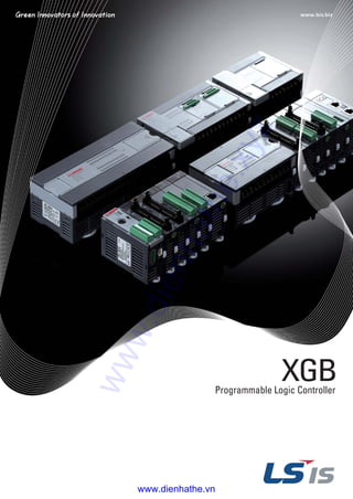
- 2. Programmable Logic Controller XGB is a micro PLC that offers maximum performance at minimum cost. With its high functionality, XGB supports from simple control system to complex task. Strengthening its communication functions, XGB offers user-oriented integrated control. Based on its strengths, XGB can be used in many application fields. All-In-One PLC With Next Generation Technology 2 www.dienhathe.xyz www.dienhathe.vn
- 3. 3 Contents Features General specifications Performance specifications Wiring Built-in functions Expansion DC Input Transistor Output Relay Output DC Input / Relay Output Analog Input Analog Output Analog Input / Output RTD Thermocouple Positioning module Communication module Option modules/Smart link Software Product list /Dimension 4 6 8 16 25 32 32 34 36 37 38 39 40 41 42 43 44 46 47 48 ▶ ▶ ▶ ▶ ▶ ▶ ▶ ▶ ▶ ▶ ▶ ▶ ▶ ▶ ▶ ▶ ▶ ▶ ▶ ▶ www.dienhathe.xyz www.dienhathe.vn
- 4. Features XBM XBC/XEC (Unit: mm) 30 114 180 27 20 90 90 90 90 90 60 64 64 60 60 DR/DN16S (16pt) DN32S (32pt) DR/DN32H (32pt) DR/DN64H (64pt) Relay output/Ethernet Others Expansion Item W H D 4 Max. 10stages Expansion Max. 10stages Analog Max. 10stagesCommunication Max. 2stages XBC/XEC (High performance type) �83ns/step processing speed �Max.10 expansion modules, Max. 384 I/O points control �Max. 5-Ch Communication with built-in functions and expansion modules XBC/XEC (Standard type) �94ns/step processing speed �Max.7 expansion modules, Max. 2 option modules, Max. 254 I/O points control �Max. 5-Ch Communication with built-in functions and expansion modules Expansion Max. 7stages Analog Max. 7stagesCommunication Max. 2 Stages Max. 2 Stages It's Slim Block type unit Standard: Max. 7 Stages (Option + Expansion) Economic: Max. 2 Stages (Option) www.dienhathe.xyz www.dienhathe.vn
- 5. H i g h With its high-speed processing and system capability, XGB offers utmost efficiency for your applications. XBC/XEC (Economic type) �240ns/step processing speed �Max. 2 option modules, Max. 38 I/O points control �2-Ch built-in communication functions (RS-232C/RS485) XBM (Standard type) �160ns/step processing speed �Max. 7 expansion modules, Max. 256 I/O points control �Max. 5-Ch Communication with built-in functions and expansion modules 5 Max. 7stages Expansion Max. 7stages Analog Max. 7stagesCommunication Max. 2stages Max. 2 Stages Modular type unit Memory RTC(Real Time Clock), Battery DC 24V, Input 4 points Transistor(Sink), Output 4 point RTD(Resistance Temperature Detect, Input 1CH) XBO-AD02A XBO-DA02A Voltage/Current, Input 2 CHs Voltage/Current, Output 2 CHs Voltage/Current, Input 1 CH Voltage/Current, Output 1 CH TC(Thermocouple), Input 2 CHs XBO-AH02A XBO-TC02A Option modules XBO-M2MB XBO-RTCA XBO-DC04A XBO-TN04A XBO-RD01A www.dienhathe.xyz www.dienhathe.vn
- 6. General specifications Block type unit (High performance, Standard, Economic) Item StandardDescriptions Ambient temperature Storage temperature Ambient humidity Storage humidity Vibration resistance Shock resistance Noise resistance Operating Ambience Altitude Pollution level*1) Cooling *1) Pollution level indicates the degree to which conductive material is generated in the environment where the equipment is used. Pollution level 2 is the condition that only non-conductive pollution occurred but temporary conductivity may be produced due to condensing. 0 ~ 55 �C -25 ~ +70 �C 5 ~ 95%RH (Non-condensing) 5 ~ 95%RH (Non-condensing) Occasional vibration Continuous vibration Frequency 10 ≤ f < 57Hz 57 ≤ f ≤ 150Hz - 9.8m/s2 (1G) 0.075mm - 10 times each direction (X, Y and Z) IEC61131-2 IEC61131-2 LSIS Standard IEC61131-2 IEC61000-4-4 IEC61131-2 IEC61000-4-3 IEC61131-2 IEC61000-4-2 10 ≤ f < 57Hz 57 ≤ f ≤ 150Hz Square wave impulse noise Electrostatic discharge Fast transient/ Burst noise Radiated electromagnetic field noise Main unit 2kV Expansion module 1kV ±500 V 4kV 80 ~ 1000MHz, 10V/m �Peak Acceleration: 147m/s2 (15g) �Duration: 11ms �Pulse waveform: Half-sine, 3times each direction per each axis Free from corrosive gases and excessive dust Up to 2,000m Less than 2 Air-cooling - 4.9m/s2 (0.5G) 0.035mm - Acceleration Pulse width Frequency Acceleration Pulse width Item StandardDescriptions Ambient temperature Storage temperature Ambient humidity Storage humidity Vibration resistance Shock resistance Noise resistance Operating Ambience Altitude Pollution level*1) Cooling *1) Pollution level indicates the degree to which conductive material is generated in the environment where the equipment is used. Pollution level 2 is the condition that only non-conductive pollution occurred but temporary conductivity may be produced due to condensing. 0 ~ 55 �C -25 ~ +70 �C 5 ~ 95%RH (Non-condensing) 5 ~ 95%RH (Non-condensing) Occasional vibration Continuous vibration Frequency 10 ≤ f < 57Hz 57 ≤ f ≤ 150Hz - 9.8m/s2 (1G) 0.075mm - 10 times each direction (X, Y and Z) IEC61131-2 IEC61131-2 LSIS Standard IEC61131-2 IEC61000-4-4 IEC61131-2 IEC61000-4-3 IEC61131-2 IEC61000-4-2 10 ≤ f < 57Hz 57 ≤ f ≤ 150Hz Square wave impulse noise Electrostatic discharge Fast transient/ Burst noise Radiated electromagnetic field noise Main unit 2kV Expansion module 1kV ±500 V 4kV 80 ~ 1000MHz, 10V/m �Peak Acceleration: 147m/s2 (15g) �Duration: 11ms �Pulse waveform: Half-sine, 3times each direction per each axis Free from corrosive gases and excessive dust Up to 2,000m Less than 2 Air-cooling - 4.9m/s2 (0.5G) 0.035mm - Acceleration Pulse width Frequency Acceleration Pulse width Modular type unit (XBM-DR16S, DN16S, DN32S) 6 www.dienhathe.xyz www.dienhathe.vn
- 7. Names and functions Programmable Logic Controller 7 DescritpionsName Descriptions Remark Input LED Condition LED Output LED Expansion module connector PADT connector Mode switch Input connector / Terminal block Output connector / Terminal block Built-in RS-485 connector Built-in RS-232C connector Power connector PADT connection Mode setting Built-in RS-485 connection Built-in RS-232C connection Power supply connection Input indication PWR: Power indication RUN: RUN indication Input wiring connection Ouput wiring connection ERR: Error indication Output LED Expansion module connector Red On: Power On Red Off: Power Off Red On: Input signal On Red Off: Input signal Off Green On: PLC Run Green Off: PLC Stop Red On-and-Off: PLC Error Red Off: PLC Normal condition On: Output signal On Off: Output signal Off Connection of expansion module (I/O, Special function, Communication) Connector for XG5000 / XG-PD connection Setting Run/Stop mode of PLC - - RS-485 +/-terminal connection RS-232C T×D, R×D, SG terminal connection DC 24V power supply � � � � � � � � � � � Modular type unit (XBM-DR16S, DN16S, DN32S) � � � � � � � � � � � No. DescritpionsName Descriptions Remark Input LED Condition LED Output LED Expansion module connector PADT connector Mode switch Input Terminal block Output Terminal block Built-in RS-485 connector Built-in RS-232C connector Power terminal Option module slot Input indication PWR: Power indication RUN: RUN indication ERR: Error indication Output LED Expansion module connector PADT connection Mode setting Input wiring connection Ouput wiring connection Built-in RS-485 connection Built-in RS-232C connection Power supply terminal Slot for option module Red On: Input signal On Red Off: Input signal Off Red On: Power On Red Off: Power Off Green On: PLC Run Green Off: PLC Stop Red On-and-Off: PLC Error Red Off: PLC Normal condition On: Output signal On Off: Output signal Off Connection of expansion module (I/O, Special function, Communication) Connector for XG5000 / XG-PD connection Setting Run/Stop mode of PLC - - RS-485 + /-terminal connection RS-232C T×D, R×D, SG terminal connection AC 110-220V power supply - Block type unit (High performance, Standard, Economic) �� �� � � � � � � � � � � � � � � � � No. � � � � www.dienhathe.xyz www.dienhathe.vn
- 8. 8 Performance specifications | Block type unit High performance type XBC-DR32H XEC-DR32H*1) XBC-DR32H/DC Item XBC-DN32H XEC-DN32H*1) XBC-DN32H/DC XBC-DR64H XEC-DR64H*1) XBC-DR64H/DC XBC-DN64H XEC-DN64H*1) XBC-DN64H/DC Perfprmance specifications Control method I/O control method Programming language Processing speed Program capacity Main Unit I/O points Max. I/O points (Main + Expansion 10 stages) Total program Operation mode Self diagnosis Program port Retain data at power failure Built-in functions Internal current consumption Weight Rated voltage Repetitive, cyclic, interrupt, constant scan Refresh mode (Batch processing by scan synchronization), Direct mode by instruction Ladder diagram or IEC standard (LD, SFC, ST)*1) 83 ns/Step 15K step (IEC type: 200KB) 128 RUN, STOP, DEBUG Detects errors of scan time, memory error, I/O error, battery error, power error, etc. USB (Rev 1.1), RS-232C 1 channel (Loader) Latch area setting at Basic parameter RS-232C / RS-485(2CH), Pulse catch, Input filter, External interrupt, PID control, High-speed counter, Positioning, RTC 32 (Input:16, Output:16) 660mA 600g 260mA 500g 1040mA 900g 330mA 800g 352 points AC 100 ~ 240V or DC24V 384 points 32 (Input:16, Output:16) 64 (Input: 32, Output: 32) 64 (Input: 32, Output: 32) Data memory XBC XEC (IEC type) P M K L F T C S D U Z N A I Q M R W F K L N U R Symbolic variable Input variable Output variable Direct variable Flag variable Flash area P0000 ~ P1023F (16,384 points) M0000 ~ M1023F (16,384 points) K0000 ~ K4095F (65,536 points) L0000 ~ L2047F (32,768 points) F0000 ~ F1023F (16,384 points) 100ms, 10ms, 1ms: T0000 ~ T1023 (1,024)(Adjustable by parameter setting) C0000 ~ C1023 (1,024) S00.00 ~ S127.99 D0000 ~ D10239 (10,240 word) U00.00 ~ U0A.31 (Analog data refresh area: 352 word) Z000 ~ Z127 (128 word) N000 ~ N5119 (5.120 word) 32KB (Max. 16KB retain setting available) 2KB (%IX 15.15.63) 2KB (%QX 15.15.63) 16KB (Max. 8KB retain setting available) 20KB (1 block) 20KB 2KB 8KB 4KB 10KB 1KB 20KB (2 blocks) *1) XEC is IEC standard language programming. www.dienhathe.xyz www.dienhathe.vn
- 9. Programmable Logic Controller 9 Standard type Repetitive, cyclic, interrupt, constant scan Refresh mode (Batch processing by scan synchronization), Direct mode by instruction Ladder diagram, Instruction List 94 ns/Step 15K step 240mA 470g 255mA 475g Data memory XBC Perfprmance specifications XBC-DN20S(U) XBC-DR20SU Item XBC-DN30S(U) XBC-DR30SU XBC-DN40S(U) XBC-DR40SU XBC-DN60S(U) XBC-DR60SU *Some products are due in market soon. Control method I/O control method Programming language Processing speed Program capacity Main Unit I/O points Max. I/O points (Main + Expansion 7 stages) Total program Operation mode Self diagnosis Program port Retain data at power failure Built-in functions Internal current consumption Weight Rated voltage 30 (Input:18, Output:12) 20 (Input:12, Output:8) 40 (Input:24, Output:16) 60 (Input:36, Output:24) 254 points244 points 264 points 284 points 128 RUN, STOP, DEBUG Detects errors of scan time, memory error, I/O error, battery error, power error, etc. RS-232C 1 channel (Loader), USB 1 channel (U-type model) Latch area setting at Basic parameter RS-232C / RS-485(2CH), Pulse catch, Input filter, External interrupt, PID control, High-speed counter, Positioning AC 100 ~ 240V undecided undecided undecided undecided undecided undecided P0000 ~ P1023F (16,384 points) M0000 ~ M1023F (16,384 points) K0000 ~ K4095F (65,536 points) L0000 ~ L2047F (32,768 points) F0000 ~ F1023F (16,384 points) 100ms, 10ms, 1ms: T0000 ~ T1023 (1,024) (Adjustable by parameter setting) C0000 ~ C1023 (1,024) S00.00 ~ S127.99 D0000 ~ D10239 (10,240 word) U00.00 ~ U0A.31(Analog data refresh area: 352 word) Z000 ~ Z127 (128 word) N0000 ~ N10236 (10.240 word) P M K L F T C S D U Z R Data area www.dienhathe.xyz www.dienhathe.vn
- 10. Performance specifications | Block type unit 10 XBC-DR10EItem XBC-DR14E XBC-DR20E XBC-DR30E Perfprmance specifications Control method I/O control method Programming language Processing speed Program capacity Main Unit I/O points Max. I/O points Total program Operation mode Self diagnosis Program port Retain data at power failure Built- in functions Internal current consumption Weight Rated voltage Repetitive, cyclic, fixed cycle operation, constant scan Refresh mode (Batch processing by scan synchronization), Direct mode by instruction Ladder diagram, Instruction List 240 ns/Step 4K step 128 RUN, STOP, DEBUG Detects errors of scan time, memory error, I/O error, battery error, power error, etc. RS-232C 1 channel (Loader) Latch area setting at Basic parameter RS-232C or RS-485(1CH), Pulse catch, Input filter, External interrupt, High-speed counter 10 (Input:6, Output:4) 250mA 330g 315mA 340g 355mA 450g 485mA 465g 14 (Main + 1option) 18 (Main + 1option) 28 (Main + 2options) 38 (Main + 2 options) AC 100 ~ 240V 14 (Input:8, Output:6) 20 (Input:12, Output:8) 30 (Input:18, Output:12) Data memory XBC P0000 ~ P127F (2,048 points) M0000 ~ M255F (4,096 points) K0000 ~ K2559F (Special area: K2600~K2559F) (40,960 points) L0000 ~ L1279F (20,480 points) F000 ~ F255F (4,096 points) 100ms, 10ms, 1ms: T000 ~ T255 (256) (Adjustable by parameter setting) C000 ~ C255 (256) S00.00 ~ S127.99 D0000 ~ D5119 (5120 word) U00.00 ~ U07.31 (Analog data refresh area: 256 word) Z000 ~ Z127 (128 word) P M K L F T C S D U Z Data area Economic type www.dienhathe.xyz www.dienhathe.vn
- 11. Programmable Logic Controller | Modular type unit 11 Repetitive, cyclic, fixed cycle operation, constant scan Refresh mode (Batch processing by scan synchronization), Direct mode by instruction Ladder diagram, Instruction List 160 ns/Step 10K step 400mA 140g 250mA 100g 280mA 100g Data memory XBM Perfprmance specifications XBM-DR16SItem XBM-DN16S XBM-DN32S *1) XBM-DR16S does not have built-in Positioning function. Control method I/O control method Programming language Processing speed Program capacity Main Unit I/O points Max. I/O points (Main + Expansion 7 stages) Total program Operation mode Self diagnosis Program port Retain data at power failure Built-in functions Internal current consumption Weight Rated voltage 16 points (Input:8, Output:8) 16 points (Input:8, Output:8) 32 points (Input:16, Output:16) 240 points 256 points 128 RUN, STOP, DEBUG Detects errors of scan time, memory error, I/O error, battery error, power error, etc. RS-232C 1 channel (Loader) Latch area setting at Basic parameter RS-232C/RS-485(2CH), Pulse catch, Input filter, External interrupt, PID control, High-speed counter, Positioning*1) DC24V P0000 ~ P127F (2,048 points) M0000 ~ M255F (4,096 points) K0000 ~ K2559F (Special area: K2600~K2559F) (40,960 points) L0000 ~ L1279F (20,480 points) F000 ~ F255F (4,096 points) 100ms, 10ms, 1ms: T000 ~ T255 (256) (Adjustable by parameter setting) C000 ~ C255 (256) S00.00 ~ S127.99 D0000 ~ D5119 (5120 word) U00.00 ~ U07.31 (Analog data refresh area: 256 word) Z000 ~ Z127 (128 word) N0000 ~ N3935 (3,936 word) P M K L F T C S D U Z N Data area Standard type www.dienhathe.xyz www.dienhathe.vn
- 12. Input/output specification | Block type unit High performance type XBC-DR32H XEC-DR32H Item XBC-DN32H XEC-DN32H XBC-DR64H XEC-DR64H XBC-DN64H XEC-DN64H XBC-DR32H/XEC-DR32H XBC-DR64H/XEC-DR64HItem Output point Insulation method Rated load voltage / current Min. load voltage / current Max. load voltage Off leakage current Max. On / Off frequency Mechanical Electrical Service life Response time Common method Off →→ On Relay insulation DC 24V 2A (Resistive load) / AC 220V 2A (COS∅ = 1), 5A / COM DC 5V / 1mA AC 250V, DC 125V 0.1mA (AC 220V, 60Hz) 3,600 times / hr 20millions times or more Rated load voltage / current 100,000 times or more AC 200V / 1.5A, AC 240V / 1A (COS∅ = 0.7) 100,000 times or more AC 200V / 1A, AC 240V / 0.5A (COS∅ = 0.35) 100,000 times or more DC 24V / 1A, DC 100V / 0.1A (L / R = 7ms) 100,000 times or more 10ms or less 12ms or less 16 points 32 points Input specification Relay output specification 12 Input points Rated input voltage Rated input current Operation voltage range On voltage / On current Off voltage / Off current Input resistance Response time Weight Off →→ On On →→ Off DC 24V 4mA (Contact 0~7: 9mA) DC 20.4 ~ 28.8V (Ripple rate < 5%) DC 19V or more / 3mA or more DC 6V or less / 1mA or less 5.6kΪ(P00 ~ P07: 2.7kΪ) 1 / 3 / 5 / 10 / 20 / 70 / 100ms (Setting by CPU parameter) Initial value: 3ms 600g 500g 900g 800g 16 points 32 points 4 points / COM P20 ~ 2F: 4 points / COM P30 ~ 3F: 8 points / COM XBC-DN32H/XEC-DN32H XBC-DN64H/XEC-DN64HItem Output point Insulation method Rated load voltage Load voltage range Max. load voltage Off leakage current Max. inrush current Max. voltage drop (On) Surge absorber Response time Common method External power supply Off →→ On On →→ Off Voltage Current Photo coupler insulation DC 12 / 24V DC 10.2 ~ 26.4 V 0.5A / 1point (P 20 ~ 23: 0.1A / point) 0.1mA or less 4A / 10ms or less DC 0.4V or less Zener Diode 1ms or less 1ms or less (Rated load, resistive load) DC 12 / 24V ± 10% (ripple voltage 4 Vp-p or less) 10mA or less (DC 24V connection) 16 points 32 points 4 points / com P20 ~ 2F: 4 points / COM P30 ~ 3F: 8 points / COM Transistor output specification www.dienhathe.xyz www.dienhathe.vn
- 13. Programmable Logic Controller Standard type 13 XBC-DN20SItem XBC-DN30SInput specification Input point Rated input voltage Rated input current Operation voltage range On voltage / On current Off voltage / Off current Input resistance Response time Weight Off →→ On On →→ Off DC 24V 4mA (Contact point 0~3:7mA) DC 20.4 ~ 28.8V (Ripple rate < 5%) DC 19V or more / 3mA or more DC 6V or less / 1mA or less 5.6kΪ(P00 ~ P07: 2.7kΪ) 1 / 3 / 5 / 10 / 20 / 70 / 100ms (Setting by CPU parameter) Initial value: 3ms 470g 475g 12 points 18 points XBC-DN20S XBC-DN30SItem Input point Insulation method Rated load voltage Load voltage range Max. load voltage Off leakage current Max. inrush current Max. voltage drop (On) Surge absorbe Response time Common method Extenal power supply Off →→ On On →→ Off Voltage Current Photo coupler insulation DC 12 / 24V DC 10.2 ~ 26.4 V 0.5A / 1 point, 2A / 1 COM 0.1mA or less 4A / 10ms or less DC0.4V or less Zener Diode 1ms or less 1ms or less (Rated load, resistive load) 4 points / com DC 12 / 24V ±10% (ripple voltage 4 Vp-p or less) 25mA or less (DC24V connection) 12 points 18 points Transistor output specification www.dienhathe.xyz www.dienhathe.vn
- 14. Input/output specification | Block type unit 14 Economic type Item Input point Insulation method Rated load voltage / current Min. load voltage / current Max. load voltage Off leakage current Max. On / Off frequency Mechanical Electrical Service life Response time Common method Off →→ On On →→ Off Relay insulation DC 24V 2A (Resistive load) / AC 220V 2A (COS∅ = 1), 5A / COM DC 5V / 1mA AC 250V, DC 125V 0.1mA (AC 220V, 60Hz) 3,600 times / hr 20 millions times or more Rated load voltage / current 100,000 times or more AC 200V / 1.5A, AC 240V / 1A (COS∅ = 0.7) 100,000 times or more AC 200V / 1A, AC 240V / 0.5A (COS∅ = 0.35) 100,000 times or more DC 24V / 1A, DC 100V / 0.1A (L / R = 7ms) 100,000 times or more 10ms or less 12ms or less Relay output specification 2 points / com 4 points / com COM0 ~ COM8: 4 points / COM COM4 ~ COM5: 8 points / COM XBC-DR10E XBC-DR14EItem XBC-DR20E XBC-DR30EInput specification Input point Rated input voltage Rated input current Operation voltage range On voltage / On current Off voltage / Off current Input resistance Response time Weight Off →→ On On →→ Off DC 24V 4mA (Contact point 0~3:7mA) DC 20.4 ~ 28.8V (Ripple rate < 5%) DC 19V or more / 3mA or more DC 6V or less / 1mA or less 5.6kΪ(P00 ~ P07: 2.7kΪ) 1 / 3 / 5 / 10 / 20 / 70 / 100ms (set by I/O parameter) Initial value: 3ms 10 points 14 points 20 points 30 points 330g 340g 450g 465g XBC-DR10E XBC-DR14E XBC-DR20E XBC-DR30E 10 points 14 points 20 points 30 points www.dienhathe.xyz www.dienhathe.vn
- 15. Programmable Logic Controller | Modular type unit 15 Standard type XBM-DN16S XBM-DN32SItem Output point Insulation method Rated load voltage Load voltage range Max. load voltage Max. inrush current Max. voltage drop (On) Response time Common method Extenal power supply External connection method Off →→ On On →→ Off Voltage Current Photo coupler insulation DC 12/24V DC 10.2 ~ 26.4 V 0.2A / 1 point (P 20 ~ 23: 0.1A / Point) 4A / 10ms or less DC 0.4V or less 1ms or less 1ms or less (Rated load, resistive load) DC 12 / 24V ±10% (ripple voltage 4 Vp-p or less) 25mA or less (DC 24V connection) 20pin connector 8 point 16 point Transistor output specification XBM-DR16SItem Output point Insulation method Rated load voltage / current Min. load voltage / current Max. load voltage Off leakage current Max. On / Off frequency Mechanical Electrical Service life Response time Common method Off → On On → Off 8 points Relay insulation DC 24V 2A (Resistive load) / AC 220V 2A (COS∅ = 1), 5A / COM DC 5V / 1mA AC 250V, DC 125V 0.1mA (AC 220V, 60Hz) 3,600 times / hr 20millions times or more Rated load voltage / current 100,000 times or more AC 200V / 1.5A, AC 240V / 1A (COS∅ = 0.7) 100,000 times or more AC 200V / 1A, AC 240V / 0.5A (COS∅ = 0.35) 100,000 times or more DC 24V / 1A, DC 100V / 0.1A (L / R = 7ms) 100,000 times or more 10ms or less 12ms or less 8 points / COM Relay output specification Input specification XBM-DN16S XBM-DN32SXBM-DR16SItem Input point Rated input voltage Rated input current Operation voltage range Response time Common Method 8 points DC24 V 4mA (00 ~ 03: 7mA) DC20.4 ~ 28.8V (ripple rate < 5%) 1 / 3 / 5 / 10 / 20 / 70 / 100ms (set by CPU parameter) Default: 3ms 8 points 16 points 16 points / COM8 points / COM Off → On On → Off 8 point / COM 16 point / COM www.dienhathe.xyz www.dienhathe.vn
- 16. Wiring | Block type unit 16 High performance type (H-Type 32 points unit) No. Conlact No. TypeConlactCircuit configurationInput wiring (XBC-DR32H /XBC-DN32H XEC-DR32H /XEC-DN32H) 485 + 485 - P00 P02 P04 P06 P08 P0A P0C P0E COM 24V TB2 TB4 TB6 TB8 TB10 TB12 TB14 TB16 TB18 TB20 TB22 TB24 TB1 TB3 TB5 TB7 TB9 TB11 TB13 TB15 TB17 TB19 TB21 TB23 RX TX SG P01 P03 P05 P07 P09 P0B P0D P0F 24G TB1 TB3 TB5 TB7 TB9 TB11 TB13 TB15 TB17 TB19 TB21 TB23 RX TX SG 01 03 05 07 09 0B 0D 0F 24G TB2 TB4 TB6 TB8 TB10 TB12 TB14 TB16 TB18 TB20 TB22 TB24 485+ 485- 00 02 04 06 08 0A 0C 0E COM 24V No. Conlact No. TypeConlactCircuit configurationTransistor output wiring (XBC-DN32H / XEC-DN32H) FG P P21 P23 P24 P26 COM 1 P29 P28 P2C P2E COM 3 TB2 TB4 TB6 TB8 TB10 TB12 TB14 TB16 TB18 TB20 TB22 TB24 TB1 TB3 TB5 TB7 TB9 TB11 TB13 TB15 TB17 TB19 TB21 TB23 AC100 ~240Y P20 P22 COM0 P25 P27 P28 P2A COM2 P2D P2F TB1 TB3 TB5 TB7 TB9 TB11 TB13 TB15 TB17 TB19 TB21 TB23 20 22 COM0 25 27 28 2A COM2 2D 2F TB2 TB4 TB6 TB8 TB10 TB12 TB14 TB16 TB18 TB20 TB22 TB24 FG DC12/24V 21 23 24 26 COM1 29 2B 2C 2E COM3 Terminal block no. DC12/24V R Internal circuit B10 B01, B02 A03 A01,A02 DC5V AC100 ~240V No. Conlact No. TypeConlactCircuit configurationRelay output wiring (XBC-DR32H / XEC-DR32H) FG NC P21 P23 P24 P26 COM 1 P29 P28 P2C P2E COM 3 TB2 TB4 TB6 TB8 TB10 TB12 TB14 TB16 TB18 TB20 TB22 TB24 TB1 TB3 TB5 TB7 TB9 TB11 TB13 TB15 TB17 TB19 TB21 TB23 AC100 ~240Y P20 P22 COM0 P25 P27 P28 P2A COM2 P2D P2F TB1 TB3 TB5 TB7 TB9 TB11 TB13 TB15 TB17 TB19 TB21 TB23 20 22 COM0 25 27 28 2A COM2 2D 2F TB2 TB4 TB6 TB8 TB10 TB12 TB14 TB16 TB18 TB20 TB22 TB24 FG NC 21 23 24 26 COM1 29 2B 2C 2E COM3 AC100 ~240V www.dienhathe.xyz www.dienhathe.vn
- 17. Programmable Logic Controller 17 High performance type (H-Type 64 points unit) No. Conlact No. TypeConlactCircuit configurationInput wiring (XBC-DR64H /XBC-DN64H XEC-DR64H / XEC-DN64H) DC24V Internal circuit R 0F 00 TB6 COM0 TB21 TB22 R DC24V R 1F 10 TB24 COM1 Terminal block no. TB39 TB40 R Photo coupler Photo coupler 485 + 485 - P00 P02 P04 P06 P08 P0A P0C P0E COM0 P10 P12 P14 P16 P18 P0A P0C P0E COM1 24V RX TX SG P01 P03 P05 P07 P09 P0B P0D P0F NC P11 P13 P15 P17 P19 P0B P0D P0F 24G TB2 TB4 TB6 TB8 TB10 TB12 TB14 TB16 TB18 TB20 TB22 TB24 TB1 TB3 TB5 TB7 TB9 TB11 TB13 TB15 TB17 TB19 TB21 TB26 TB28 TB30 TB32 TB34 TB36 TB38 TB40 TB42 TB23 TB25 TB27 TB29 TB31 TB33 TB35 TB37 TB39 TB41 TB1 TB3 TB5 TB7 TB9 TB11 TB13 TB15 TB17 TB19 TB21 TB23 TB25 TB27 TB29 TB31 TB33 TB35 TB37 TB39 TB41 RX TX SG 01 03 05 07 09 0B 0D 0F NC 11 13 15 17 19 1B 1D 1F 24G TB2 TB4 TB6 TB8 TB10 TB12 TB14 TB16 TB18 TB20 TB22 TB24 TB26 TB28 TB30 TB32 TB34 TB36 TB38 TB40 TB42 485+ 485- 00 02 04 06 08 0A 0C 0E COM0 10 12 14 16 18 1A 1C 1E COM1 24V Transistor output wiring (XBC-DN64H /XEC-DN64H) No. Conlact No. TypeConlactCircuit configuration TB23 TB25 TB27 TB29 TB31 TB33 TB35 TB37 TB39 TB41 P31 P33 P35 P37 P38 P3A P3C P3E COM 5 AC100 ~240Y P20 P30 P32 P34 P36 COM 4 P40 P3B P3D P3F TB2 TB4 TB6 TB8 TB10 TB12 TB14 TB16 TB18 TB20 TB22 TB24 TB1 TB3 TB5 TB7 TB9 TB11 TB13 TB15 TB17 TB19 TB21 TB26 TB28 TB30 TB32 TB34 TB36 TB38 TB40 TB42 FG P P21 P23 P24 P26 COM 1 P29 P2B P2C P2E COM 3 P22 COM0 P25 P27 P28 P2A COM2 P2D P2F TB1 TB3 TB5 TB7 TB9 TB11 TB13 TB15 TB17 TB19 TB21 TB23 TB25 TB27 TB29 TB31 TB33 TB35 TB37 TB39 TB41 20 22 COM0 25 27 28 2A COM2 2D 2F 30 32 34 36 COM4 39 3B 3D 3F TB2 TB4 TB6 TB8 TB10 TB12 TB14 TB16 TB18 TB20 TB22 TB24 TB26 TB28 TB30 TB32 TB34 TB36 TB38 TB40 TB42 FG DC12/24V 21 23 24 26 COM1 29 2B 2C 2E COM3 31 33 35 37 38 3A 3C 3E COM5 AC100 ~240V www.dienhathe.xyz www.dienhathe.vn
- 18. Wiring | Block type unit 18 High performance type (H-Type 64 points unit) Standard type No. Conlact No. TypeConlactCircuit configurationInput wiring (XBC-DN20S (U) / XBC-DR20SU) DC24V Internal circuit R B 0 0 TB6 COM DC5VPhoto coupler Terminal block no. TB17 TB24 LED R 485 + 485 - P00 P02 P04 P06 P08 P0A NC NC NC COM TB2 TB4 TB6 TB8 TB10 TB12 TB14 TB16 TB18 TB20 TB22 TB24 TB1 TB3 TB5 TB7 TB9 TB11 TB13 TB15 TB17 TB19 TB21 TB23 RX TX SG P01 P03 P05 P07 P09 P0B NC NC NC TB1 TB3 TB5 TB7 TB9 TB11 TB13 TB15 TB17 TB19 TB21 TB23 RX TX SG 01 03 05 07 09 0B NC NC NC TB2 TB4 TB6 TB8 TB10 TB12 TB14 TB16 TB18 TB20 TB22 TB24 485+ 485- 00 02 04 06 08 0A NC NC NC COM Relay output wiring (XBC-DR64H /XEC-DR64H) No. Conlact No. TypeConlactCircuit configuration TB23 TB25 TB27 TB29 TB31 TB33 TB35 TB37 TB39 TB41 P31 P33 P35 P37 P38 P3A P3C P3E AC100 ~240Y P20 P30 P32 P34 P36 COM 4 P40 P3B P3D P3F TB2 TB4 TB6 TB8 TB10 TB12 TB14 TB16 TB18 TB20 TB22 TB24 TB1 TB3 TB5 TB7 TB9 TB11 TB13 TB15 TB17 TB19 TB21 TB26 TB28 TB30 TB32 TB34 TB36 TB38 TB40 TB42 FG NC P21 P23 P24 P26 COM 1 P29 P2B P2C P2E COM 3 P22 COM0 P25 P27 P28 P2A COM2 P2D P2F COM 5 TB1 TB3 TB5 TB7 TB9 TB11 TB13 TB15 TB17 TB19 TB21 TB23 TB25 TB27 TB29 TB31 TB33 TB35 TB37 TB39 TB41 20 22 COM0 25 27 28 2A COM2 2D 2F 30 32 34 36 COM4 39 3B 3D 3F TB2 TB4 TB6 TB8 TB10 TB12 TB14 TB16 TB18 TB20 TB22 TB24 TB26 TB28 TB30 TB32 TB34 TB36 TB38 TB40 TB42 FG NC 21 23 24 26 COM1 29 2B 2C 2E COM3 31 33 35 37 38 3A 3C 3E COM5 AC100 ~240V www.dienhathe.xyz www.dienhathe.vn
- 19. Programmable Logic Controller 19 No. Conlact No. TypeConlactCircuit configurationTransistor output wiring (XBC-DN20S(U)) Internalcircuit Terminal no. TB05 TB07 TB04 TB9 TB10 TB06 TB13 TB14 TB08 TB15 TB16 TB12 TB11 DC5V R R R R DC12/24V DC12/24V DC12/24V DC12/24V FG COM 0 COM 1 COM2 P43 COM3 P45 P47 NC NC NC 24G TB2 TB4 TB6 TB8 TB10 TB12 TB14 TB16 TB18 TB20 TB22 TB24 TB1 TB3 TB5 TB7 TB9 TB11 TB13 TB15 TB17 TB19 TB21 TB23 AC100 ~240Y P40 P41 P42 P P44 P46 NC NC NC 24V TB1 TB3 TB5 TB7 TB9 TB11 TB13 TB15 TB17 TB19 TB21 TB23 40 41 42 P 44 46 NC NC NC 24V TB2 TB4 TB6 TB8 TB10 TB12 TB14 TB16 TB18 TB20 TB22 TB24 FG COM0 COM1 COM2 43 COM3 45 47 NC NC NC 24G AC100 ~240V No. Conlact No. TypeConlactCircuit configurationRelay output wiring (XBC-DR20SU) Terminal No. Internalcircuit TB5 TB4 TB7 TB6 TB9 COM0 COM1 TB8COM2 TB10 TB12COM3 TB16 RY RY RY RY FG COM 0 COM 1 COM2 P43 COM3 P45 P47 NC NC NC 24G TB2 TB4 TB6 TB8 TB10 TB12 TB14 TB16 TB18 TB20 TB22 TB24 TB1 TB3 TB5 TB7 TB9 TB11 TB13 TB15 TB17 TB19 TB21 TB23 AC100 ~240Y P40 P41 P42 NC P44 P46 NC NC NC 24V TB1 TB3 TB5 TB7 TB9 TB11 TB13 TB15 TB17 TB19 TB21 TB23 40 41 42 NC 44 46 NC NC NC 24V TB2 TB4 TB6 TB8 TB10 TB12 TB14 TB16 TB18 TB20 TB22 TB24 FG COM0 COM1 COM2 43 COM3 45 47 NC NC NC 24G AC100 ~240V No. Conlact No. TypeConlactCircuit configurationInput wiring (XBC-DN30S(U)/ XBC-DR30SU) DC24V Internal circuit R 11 0 TB6 COM DC5V Photo coupler Terminal block no. TB23 TB24 LED R 485 + 485 - P00 P02 P04 P06 P08 P0A P0C P0E P10 COM TB2 TB4 TB6 TB8 TB10 TB12 TB14 TB16 TB18 TB20 TB22 TB24 TB1 TB3 TB5 TB7 TB9 TB11 TB13 TB15 TB17 TB19 TB21 TB23 RX TX SG P01 P03 P05 P07 P09 P0B P0D P0F P11 TB1 TB3 TB5 TB7 TB9 TB11 TB13 TB15 TB17 TB19 TB21 TB23 RX TX SG 01 03 05 07 09 0B 0D 0F 11 TB2 TB4 TB6 TB8 TB10 TB12 TB14 TB16 TB18 TB20 TB22 TB24 485+ 485- 00 02 04 06 08 0A 0C 0E 10 COM www.dienhathe.xyz www.dienhathe.vn
- 20. Wiring | Block type unit 20 No. Conlact No. TypeConlactCircuit configurationTransistor output wiring (XBC-DN30S(U)) Internalcircuit Terminal block no. TB05 TB07 TB04 TB10 TB08 TB20 TB22 TB18 TB11 TB13 TB06 TB15 TB18 DC5V R R R R DC12/24V DC12/24V DC12/24V DC12/24V FG COM 0 COM 1 COM2 P43 COM3 P45 P47 COM4 P49 P4B 24G TB2 TB4 TB6 TB8 TB10 TB12 TB14 TB16 TB18 TB20 TB22 TB24 TB1 TB3 TB5 TB7 TB9 TB11 TB13 TB15 TB17 TB19 TB21 TB23 AC100 ~240Y P40 P41 P42 P P44 P46 NC P48 P4A 24V TB1 TB3 TB5 TB7 TB9 TB11 TB13 TB15 TB17 TB19 TB21 TB23 40 41 42 P 44 46 NC 48 4A 24V TB2 TB4 TB6 TB8 TB10 TB12 TB14 TB16 TB18 TB20 TB22 TB24 FG COM0 COM1 COM2 43 COM3 45 47 COM4 49 4B 24G No. Conlact No. TypeConlactCircuit configurationRelay output wiring (XBC-DR30SU) Terminal No. InternalCircuit TB5 TB4 TB7 TB6 TB9 COM0 COM1 TB8COM2 TB10 TB12COM3 TB16 TB13 TB18COM4 TB22 TB19 FG COM 0 COM 1 COM2 P43 COM3 P45 P47 COM4 P49 P4B 24G TB2 TB4 TB6 TB8 TB10 TB12 TB14 TB16 TB18 TB20 TB22 TB24 TB1 TB3 TB5 TB7 TB9 TB11 TB13 TB15 TB17 TB19 TB21 TB23 AC100 ~240Y P40 P41 P42 NC P44 P46 NC P48 P4A 24V TB1 TB3 TB5 TB7 TB9 TB11 TB13 TB15 TB17 TB19 TB21 TB23 40 41 42 NC 44 46 NC 48 4A 24V TB2 TB4 TB6 TB8 TB10 TB12 TB14 TB16 TB18 TB20 TB22 TB24 FG COM0 COM1 COM2 43 COM3 45 47 COM4 49 4B 24G Standard type Economic type No. Conlact No. TypeConlactCircuit configurationInput wiring (XBC-DR10E) DC24V Internal circuit R 5 0 TB6 COM DC5V Terminal block no. TB11 TB14 LED R Photo coupler 485 + 485 - P00 P02 P04 NC COM TB2 TB4 TB6 TB8 TB10 TB12 TB14 TB1 TB3 TB5 TB7 TB9 TB11 TB13 RX TX SG P01 P03 P05 NC TB1 TB3 TB5 TB7 TB9 TB11 TB13 RX TX SG 01 03 05 NC TB2 TB4 TB6 TB8 TB10 TB12 TB14 485+ 485- 00 02 04 NC COM AC100 ~240V AC100 ~240V www.dienhathe.xyz www.dienhathe.vn
- 21. Programmable Logic Controller 21 No. Conlact No. TypeConlactCircuit configurationInput wiring (XBC-DR14E) DC24V Internal circuit R 7 0 TB6 COM DC5V Photocoupler Terminal block no. TB13 TB14 LED R 485 + 485 - P00 P02 P04 P06 COM TB2 TB4 TB6 TB8 TB10 TB12 TB14 TB1 TB3 TB5 TB7 TB9 TB11 TB13 RX TX SG P01 P03 P05 P07 TB1 TB3 TB5 TB7 TB9 TB11 TB13 RX TX SG 01 03 05 07 TB2 TB4 TB6 TB8 TB10 TB12 TB14 485+ 485- 00 02 04 06 08 No. Conlact No. TypeConlactCircuit configurationRelay output wiring (XBC-DR10E) Terminal no. RRYY Internalcircuit TB5 TB4 RRYY TB7 TB6 TB9 COM0 COM1 RRYY TB8COM2 TB10 FG COM 0 COM 1 COM2 P43 NC 24G TB2 TB4 TB6 TB8 TB10 TB12 TB14 TB1 TB3 TB5 TB7 TB9 TB11 TB13 AC100 ~240Y P40 P41 P42 NC 24V TB1 TB3 TB5 TB7 TB9 TB11 TB13 40 41 42 NC 24V TB2 TB4 TB6 TB8 TB10 TB12 TB14 FG COM0 COM1 COM2 43 NC 24G AC100 ~240V No. Conlact No. TypeConlactCircuit configurationRelay output wiring (XBC-DR14E) Terminal no. RY RY RY Internalcircuit TB5 TB4 TB7 TB6 TB9 COM0 COM1 TB8COM2 TB12 FG COM 0 COM 1 COM2 P43 NC 24G TB2 TB4 TB6 TB8 TB10 TB12 TB14 TB1 TB3 TB5 TB7 TB9 TB11 TB13 AC100 ~240Y P40 P41 P42 NC 24V TB1 TB3 TB5 TB7 TB9 TB11 TB13 40 41 42 NC 24V TB2 TB4 TB6 TB8 TB10 TB12 TB14 FG COM0 COM1 COM2 43 NC 24G AC100 ~240V No. Conlact No. TypeConlactCircuit configurationInput wiring (XBC-DR20E) DC24V Internal circuit R 0B 0 TB6 COM DC5V Photo coupler Terminal block no. TB17 TB24 LED R 485 + 485 - P00 P02 P04 P06 P08 P0A NC NC NC COM TB2 TB4 TB6 TB8 TB10 TB12 TB14 TB16 TB18 TB20 TB22 TB24 TB1 TB3 TB5 TB7 TB9 TB11 TB13 TB15 TB17 TB19 TB21 TB23 RX TX SG P01 P03 P05 P07 P09 P0B NC NC NC TB1 TB3 TB5 TB7 TB9 TB11 TB13 TB15 TB17 TB19 TB21 TB23 RX TX SG 01 03 05 07 09 0B NC NC NC TB2 TB4 TB6 TB8 TB10 TB12 TB14 TB16 TB18 TB20 TB22 TB24 485+ 485- 00 02 04 06 08 0A NC NC NC COM www.dienhathe.xyz www.dienhathe.vn
- 22. Wiring | Block type unit 22 Economic type No. Conlact No. TypeConlactCircuit configurationInput wiring(XBC-DR30E) DC24V Internal circuit R 11 0 TB6 COM DC5V Photo coupler Terminal block no. TB23 TB24 LED R 485 + 485 - P00 P02 P04 P06 P08 P0A P0C P0E P10 COM TB2 TB4 TB6 TB8 TB10 TB12 TB14 TB16 TB18 TB20 TB22 TB24 TB1 TB3 TB5 TB7 TB9 TB11 TB13 TB15 TB17 TB19 TB21 TB23 RX TX SG P01 P03 P05 P07 P09 P0B P0D P0F P11 TB1 TB3 TB5 TB7 TB9 TB11 TB13 TB15 TB17 TB19 TB21 TB23 RX TX SG 01 03 05 07 09 0B 0D 0F 11 TB2 TB4 TB6 TB8 TB10 TB12 TB14 TB16 TB18 TB20 TB22 TB24 485+ 485- 00 02 04 06 08 0A 0C 0E 10 COM No. Conlact No. TypeConlactCircuit configurationRelay output wiring (XBC-DR30E) Terminal No. InternalCircuit TB5 TB4 TB7 TB6 TB9 COM0 COM1 TB8COM2 TB10 TB12COM3 TB16 TB13 TB18COM4 TB22 TB19 FG COM 0 COM 1 COM2 P43 COM3 P45 P47 COM4 P49 P4B 24G TB2 TB4 TB6 TB8 TB10 TB12 TB14 TB16 TB18 TB20 TB22 TB24 TB1 TB3 TB5 TB7 TB9 TB11 TB13 TB15 TB17 TB19 TB21 TB23 AC100 ~240Y P40 P41 P42 NC P44 P46 NC P48 P4A 24V TB1 TB3 TB5 TB7 TB9 TB11 TB13 TB15 TB17 TB19 TB21 TB23 40 41 42 NC 44 46 NC 48 4A 24V TB2 TB4 TB6 TB8 TB10 TB12 TB14 TB16 TB18 TB20 TB22 TB24 FG COM0 COM1 COM2 43 COM3 45 47 COM4 49 4B 24G AC100 ~240V No. Conlact No. TypeConlactCircuit configurationRelay output wiring (XBC-DR20E) Terminal No. RY RY RY RY Internalcircuit TB5 TB4 TB7 TB6 TB9 COM0 COM1 TB8COM2 TB10 TB12COM3 TB16 TB1 3 FG COM 0 COM 1 COM2 P43 COM3 P45 P47 COM4 P49 P4B 24G TB2 TB4 TB6 TB8 TB10 TB12 TB14 TB16 TB18 TB20 TB22 TB24 TB1 TB3 TB5 TB7 TB9 TB11 TB13 TB15 TB17 TB19 TB21 TB23 AC100 ~240Y P40 P41 P42 NC P44 P46 NC P48 P4A 24V TB1 TB3 TB5 TB7 TB9 TB11 TB13 TB15 TB17 TB19 TB21 TB23 40 41 42 NC 44 46 NC 48 4A 24V TB2 TB4 TB6 TB8 TB10 TB12 TB14 TB16 TB18 TB20 TB22 TB24 FG COM0 COM1 COM2 43 COM3 45 47 COM4 49 4B 24G AC100 ~240V www.dienhathe.xyz www.dienhathe.vn
- 23. Programmable Logic Controller 23 Standard type No. TypeConlactCircuit configurationInput wiring(XBM-DR16S) DC24V Internal Circuit R 7 0 TB1 COM Photo coupler Terminal block no. TB8 TB9 R TB1 TB2 TB3 TB4 TB5 TB6 TB7 TB8 TB9 00 01 02 03 04 05 06 07 COM No. TypeConlactCircuit configurationRelay output wiring (XBM-DR16S) Terminal block no. DC5V RY Internal circuit TB1 TB9 TB8 TB1 TB2 TB3 TB4 TB5 TB6 TB7 TB8 TB9 20 21 22 23 24 25 26 27 COM No. TypeConlactCircuit configurationInput wiring(XBM-DN16S) Terminal block no. DC12/24V RR Internal circuit B10 B01, B02 B03 A01, A02 DC5V A10 A09 A08 A07 A06 A05 A04 A03 A02 A01 NC NC NC NC NC NC NC NC NC NC B10 B09 B08 B07 B06 B05 B04 B03 B02 B01 00 01 02 03 04 05 06 07 COM COM No. Conlact | Modular type unit www.dienhathe.xyz www.dienhathe.vn
- 24. Wiring | Modular type unit 24 Standard type No. TypeConlactCircuit configurationInput wiring(XBM-DN32S) DC24V Internal circuit R F 0 B10 COM Photo coupler Terminal block no. A03 B02 R A10 A09 A08 A07 A06 A05 A04 A03 A02 A01 08 09 0A 0B 0C 0D 0E 0F COM COM B10 B09 B08 B07 B06 B05 B04 B03 B02 B01 00 01 02 03 04 05 06 07 COM COM No. Conlact No. TypeConlactCircuit configurationTransistor output wiring (XBM-DN16S) Terminal block no. DC12/24V R Internal circuit B10 B01, B02 A03 A01, A02 DC5V B10 B09 B08 B07 B06 B05 B04 B03 B02 B01 A10 A09 A08 A07 A06 A05 A04 A03 A02 A01 20 21 22 23 24 25 26 27 NC NC NC NC NC NC NC NC DC12/ 24V COM No. TypeConlactCircuit configurationTransistor output wiring (XBM-DN32S) B10 B09 B08 B07 B06 B05 B04 B03 B02 B01 A10 A09 A08 A07 A06 A05 A04 A03 A02 A01 20 21 22 23 24 25 26 27 28 29 2A 2B 2C 2D 2E 2F DC12/ 24V COM Terminal block no. DC12/24V R Internal circuit B10 B01, B02 A03 A01, A02 DC5V www.dienhathe.xyz www.dienhathe.vn
- 25. Built-in functions | High-speed counter Programmable Logic Controller 25 DescriptionItem Input voltage Input current On voltage (min.) Off voltage (max.) 24V DC (20.4V ~ 28.8V) 4mA 20.4V 6V Input specification Description Block type unit H-type S(U)-type E-type S-type Modular typeClassification Performance specifications A-phase, B-phase Voltage input (Open collector) DC 24V Signed 32bit (-2,147,483,648 ~ 2,147,483,647) Linear count (if 32bit range exceeded, Carry / Borrow occurs) Ring count (repeated count within setting range) 1-phase input 2-phase input CW/CCW input Voltage Increasing / decreasing operation setting by B-phase input Increasing/decreasing operation setting by program Automatic setting by difference in phase A-phase input: increasing operation B-phase input: decreasing operation 1 multiplication 4 multiplication 1 multiplication Preset instruction input DC 24V input type Voltage 100kpps 100kpps 4ch / 20kpps 4ch 50kpps 2ch / 10kpps 2ch 50kpps 2ch / 8kpps 2ch 100kpps 2ch / 20kpps 6ch 4kpps 4ch 20kpps 4ch 2 multiplication: 10kpps 4 multiplication: 8kpps 100kpps 50kpps 1ch 8kpps 3ch 2 point/channel (for each channel): output contact point of basic unit available Select program setting, signal-compared (>, >=, =, <=, <) or section compared output (included or excluded) Relay, Open-collector output (Sink) To be set through program To be set through terminal (contact) or program Count latch 1 point/channel (for each channel): output contact point of basic unit available 2kpps 2ch 4kpps 20kpps Count input Signal Number of channels Max. count speed Count range Signal type 1 phase input 2 phase input 1 phase input 2 phase input CW/CCW Signal Signal level Signal type Type Output Type Count enable Preset function Auxiliary mode Output points CW/CCW Count mode (Program setting) Input mode (Program setting) Up/Down setting Multiplication function Control input External output 1 phase 2 phase Signal Input type Signal level www.dienhathe.xyz www.dienhathe.vn
- 26. Built-in functions | High-speed counter 26 Names Usage Terminal No. P000 P001 P002 P003 P004 P005 P006 P007 P008 P009 P00A P00B P00C P00D P00E P00F COM0 Ch0 counter input Ch1 counter input Ch2 counter input Ch3 counter input Ch4 counter input Ch5 counter input Ch6 counter input Ch7 counter input Ch0 preset 24V Ch1 preset 24V Ch2 preset 24V Ch4 preset 24V Ch5 preset 24V Ch6 preset 24V Ch7 preset 24V Ch8 preset 24V Input common Ch0 A-phase input Ch0 B-phase input Ch2 A-phase input Ch2 B-phase input Ch4 A-phase input Ch4 B-phase input Ch6 A-phase input Ch6 B-phase input Ch0 preset 24V - Ch2 preset 24V - Ch4 preset 24V - Ch6 preset 24V - Input common Counter input terminal Counter input terminal Counter input terminal Counter input terminal Counter input terminal Counter input terminal Counter input terminal Counter input terminal Preset input terminal Preset input terminal Preset input terminal Preset input terminal Preset input terminal Preset input terminal Preset input terminal Preset input terminal Input common A-phase input B-phase input A-phase input B-phase input A-phase input B-phase input A-phase input B-phase input Preset input terminal No use Preset input terminal No use Preset input terminal No use Preset input terminal No use Input common 1-phase 2-Phase 1-phase 2-Phase Names Usage Terminal No. IX0.0.0 IX0.0.1 IX0.0.2 IX0.0.3 IX0.0.4 IX0.0.5 IX0.0.6 IX0.0.7 IX0.0.8 IX0.0.9 IX0.0.10 IX0.0.11 IX0.0.12 IX0.0.13 IX0.0.14 IX0.0.15 COM0 Ch0 counter input Ch1 counter input Ch2 counter input Ch3 counter input Ch4 counter input Ch5 counter input Ch6 counter input Ch7 counter input Ch0 preset 24V Ch1 preset 24V Ch2 preset 24V Ch4 preset 24V Ch5 preset 24V Ch6 preset 24V Ch7 preset 24V Ch8 preset 24V Input common Ch0 A-phase input Ch0 B-phase input Ch2 A-phase input Ch2 B-phase input Ch4 A-phase input Ch4 B-phase input Ch6 A-phase input Ch6 B-phase input Ch0 preset 24V - Ch2 preset 24V - Ch4 preset 24V - Ch6 preset 24V - Input common Counter input terminal Counter input terminal Counter input terminal Counter input terminal Counter input terminal Counter input terminal Counter input terminal Counter input terminal Preset input terminal Preset input terminal Preset input terminal Preset input terminal Preset input terminal Preset input terminal Preset input terminal Preset input terminal Input common A-phase input B-phase input A-phase input B-phase input A-phase input B-phase input A-phase input B-phase input Preset input terminal No use Preset input terminal No use Preset input terminal No use Preset input terminal No use Input common 1-phase 2-Phase 1-phase 2-Phase Parts designation | Block type unit High performance type (XBC-H) High performance type (XEC-H) Standard type Names Usage Terminal No. P000 P001 P002 P003 P004 P005 P006 P007 P008 P009 P00A P00B P00C P00D P00E P00F COM0 Ch0 counter input Ch1 counter input Ch2 counter input Ch3 counter input Ch4 counter input Ch5 counter input Ch6 counter input Ch7 counter input Ch0 preset 24V Ch1 preset 24V Ch2 preset 24V Ch4 preset 24V Ch5 preset 24V Ch6 preset 24V Ch7 preset 24V Ch8 preset 24V Input common Ch0 A-phase input Ch0 B-phase input Ch2 A-phase input Ch2 B-phase input Ch4 A-phase input Ch4 B-phase input Ch6 A-phase input Ch6 B-phase input Ch0 preset 24V - Ch2 preset 24V - Ch4 preset 24V - Ch6 preset 24V - Input common Counter input terminal Counter input terminal Counter input terminal Counter input terminal Counter input terminal Counter input terminal Counter input terminal Counter input terminal Preset input terminal Preset input terminal Preset input terminal Preset input terminal Preset input terminal Preset input terminal Preset input terminal Preset input terminal Input common A-phase input B-phase input A-phase input B-phase input A-phase input B-phase input A-phase input B-phase input Preset input terminal No use Preset input terminal No use Preset input terminal No use Preset input terminal No use Input common 1-phase 2-Phase 1-phase 2-Phase www.dienhathe.xyz www.dienhathe.vn
- 27. Programmable Logic Controller 27 Wiring Voltage output encoder Open collector encoder Names Usage Terminal No. P000 P001 P002 P003 P004 P005 P006 P007 COM0 Ch0 counter input Ch1 counter input Ch2 counter input Ch3 counter input Ch0 preset 24V Ch1 preset 24V Ch2 preset 24V Ch4 preset 24V Input common Ch0 A-phase input Ch0 B-phase input Ch2 A-phase input Ch2 B-phase input Ch0 preset 24V - Ch2 preset 24V - Input common Counter input terminal Counter input terminal Counter input terminal Counter input terminal Preset input terminal Preset input terminal Preset input terminal Preset input terminal Common terminal A-phase input B-phase input A-phase input B-phase input Preset input terminal No use Preset input terminal No use Common terminal 1-phase 2-Phase 1-phase 2-Phase Names Usage Terminal No. P000 P001 P002 P003 P004 P005 P006 P007 COM0 Ch0 counter input Ch1 counter input Ch2 counter input Ch3 counter input Ch0 preset 24V Ch1 preset 24V Ch2 preset 24V Ch3 preset 24V Input common Ch0 A-phase input Ch0 B-phase input Ch2 A-phase input Ch2 B-phase input Ch0 preset 24V - Ch2 preset 24V - Input common Counter input terminal Counter input terminal Counter input terminal Counter input terminal Preset input terminal Preset input terminal Preset input terminal Preset input terminal Common terminal A-phase input B-phase input A-phase input B-phase input Preset input terminal No use Preset input terminal No use Common terminal 1-phase 2-Phase 1-phase 2-Phase Economic type Parts designation | Modular type unit Standard type www.dienhathe.xyz www.dienhathe.vn
- 28. Built-in functions | Positioning 28 ※Economic block type unit (E-type) dose not support built-in Positioning functions Electrical specification Output Input Signal Rated input voltage Load voltage range Max. load current/inrush current Max. voltage drop (On) Leakage current (Off) Response time Signal Rated input voltage/current Load voltage range On voltage/current Off voltage/current Input resistance Response time Output pulse External high limit External low limit Approximate zero zero DC 24V/7mA DC 20.4 ~ 28.8V DC 24V/4mA DC 19V/5.7mA or more DC 19V/3.4mA or more DC 6V/1.8mA or less DC 6V/1.1mA or less 3.3Ϊ 5.6Ϊ 0.5ms or less DC 5~24V DC 4.75~26.4V DC 0.3V or less 0.1mA or less 100㎲ or less 100mA(1 point) 1A/10ms or less Description Block type unit Modular type H-type S(U)-type S-type Classification No. of control axis Interpolation Control mode Control unit Positioning data Positioning monitor Back-up Positioning Max. output pulse Max. distance of connection 2 axes 2-axis linear interpolation Position control, Speed control, Speed/Position switching control, Position/speed switching control Pulse 30-step pattern for each axis (XBC: 80step) (operation step number : 1~ 30, XBC : 1~ 80) Dedicated monitoring function for positioning in XG5000 Permanent Backup of downloaded parameter (FLASH memory) 2-month Super Cap.Backup of parameter/data modified during operation(XBM)Battery back-up (XBC) PermanentBackupofparameter/datainRAMbyinstruction(FLASH memory) Absolute / incremental method -2,147,483,648 ~ 2,147,483,647 1 � 100,000 (pulse/sec) Trapezoidal acceleration / deceleration 1 � 10,000㎳ (4 patterns each can be set) 100 Kpps 2m Performance specification Positioning method Positioning range Speed range Acceleration / Deceleration type Acceleration / Deceleration time www.dienhathe.xyz www.dienhathe.vn
- 29. Programmable Logic Controller 29 Standard type Signal name XBC pin number (XEC pin number) X axis Y axis Operating condition Direction of positioning signal to external Item Input Output Limit L Limit H DOG Origin Input COM Pulse Direction DC12V Output COM ← ← ← ← ← → → → → Low limit High limit Near point Zero signal (+24V) Common External power supply External 24V GND COM P COM 0 ~3 P00008 (%IX0.0.8) P00009 (%IX0.0.9) P0000C (%IX0.0.12) P0000D (%IX0.0.13) P00020 (%QX0.0.0) Pulse/CW (Open collector) DC5~24V 4mA/ 24V Direction/CCW (Open collector) P00022 (%QX0.0.2) P00021 (%QX0.0.1) P00023 (%QX0.0.3) P0000A (%IX0.0.10) P0000B (%IX0.0.11) P0000E (%IX0.0.14) P0000F (%IX0.0.15) High performance type (XBC-H/XEC-H) XBM pin number Item Limit L Limit H DOG Origin Input COM Pulse Direction DC12/24V Output COM ← ← ← ← ← → → → → Edge Edge Edge Edge - - - - - P00000 P00001 P00004 P00005 P00020 P00022 P00002 P00003 P00006 P00007 P00021 P00023 Low limit High limit Near point Zero signal (+24V) Common Pulse/CW (Open collector) Direction/CCW (Open collector) External power supply External 24V GND Y axis Signal name Operating condition Direction of positioning signal to externalX axis Input Output I/O specifications | Block type unit I/O specifications | Modular type unit Signal name XBC pin number X axis Y axis Operating condition Direction of positioning signal to external Item Input Output Limit L Limit H DOG Origin Input COM Pulse Direction DC12V Output COM ← ← ← ← ← → → → → Low limit High limit Near point Zero signal (+24V) Common External power supply External 24V GND COM COM 12/24V COM P COM 0~3 P00008 (%IX0.0.8) P00009 (%IX0.0.9) P0000C (%IX0.0.12) P0000D (%IX0.0.13) P00040 (%QX0.0.0) Pulse/CW (Open collector) DC5~24V 4mA/ 24V Direction/CCW (Open collector) P00042 (%QX0.0.2) P00041 (%QX0.0.1) P00043 (%QX0.0.3) P0000A (%IX0.0.10) P0000B (%IX0.0.11) P0000E (%IX0.0.14) P0000F (%IX0.0.15) Standard type (XBC-S(U)) www.dienhathe.xyz www.dienhathe.vn
- 30. 30 Built-in functions | PID/Pulse catch/Input filter/Task/RTC Pulse catch When the On-condition time of input signal is shorter than 1 scan time (Min. 50㎲), Pulse catch processes the input signal as normal input. External input signal Input image data Input filter Input filter prevents processing of the input signal that is shorter than the filtering time. (Filtering time is set by parameter) In the application site where noise is frequently generated, input filter prevents wrong input caused by noise. External input signal Input image data Description Block type unit Modular type H-type S(U)-type S-type Classification Performance specification (PID) No. of control loop Control mode Control period Function 16-loop independent control P control, PI control, PD control, PID control 10ms ~ 6,563.5ms (Setting unit: 0.1ms) Switching control direction automatically when exceeding dead band Improved control precision by serial connection between Master loop and Slave loop Preventing overload caused by excessive SV change by setting variation slope Improved control stability with various alarm function such as MV high limit/low limit, PV high limit/low limit, PV variation width Auto tuning with improved auto-tuning algorithm PWM output, PV Tracking, �MV, �PV, etc Forward/Reverse Mixed control Cascade SV Ramp Alarm Auto tuning Additional function ※Economic block type unit (E-type) dose not support built-in PID functions Description Block type unit Modular type S(U)-typeH-type E-type S-type Item Pulse catch 10㎲: 4 points (P00000~P00003) 50㎲: 4 points (P00004~P00007) 10㎲: 2 points (P00000~P00001) 50㎲: 6 points (P00002~P00007) 50㎲: 4 points (P00000~P00003) 50㎲: 8 points (P00000~P00007) Description Block type unit Modular type S(U)-typeH-type E-type S-type Classification No. of setting points Input filtering time setting Setting range Every input contact Assigning for each module 1 ~ 100㎳ (1,3,5,10,20,70,100) www.dienhathe.xyz www.dienhathe.vn
- 31. Programmable Logic Controller 31 Task Task function is the processing method of internal/external signal generated periodically or aperiodically. It stops operation of scan program for the moment and then execute the assigned task. RTC RTC function is for time management of system and error log. RTC function is executed steadily when power is off or instantaneous power cut status. Current time of RTC is renewed every scan by system operation status information flag. Description Block type unit Modular type S(U)-typeH-type E-type S-type Classification RTC Built-in Option module Option module Not available Description Block type unit Modular type S(U)-typeH-type E-type S-type Classification Initial task Cyclic task I/O task Internal device task External interrupt 1(_INT) 8 8 8 8 4 8 10㎲: 4 points (P00000~P00003) 50㎲: 4 points (P00004~P00007) 10㎲: 2 points (P00000~P00001) 50㎲: 6 points (P00002~P00007) 50㎲: 4 points (P00000~P00003) 50㎲: 8 points (P00000~P00007) www.dienhathe.xyz www.dienhathe.vn
- 32. 32 Expansion | DC Input Model XBE-DC08A XBE-DC16A XBE-DC32A Specification Input point Rated input voltage / current Operation voltage range Input resistance Response time Insulation pressure Insulation resistance COMMON method Internal current consumption Off → On On → Off DC 24V / 4mA DC 20.4 ~ 28.8V (Ripple rate < 5%) 5.6kΪ 1 / 3 / 5 / 10 / 20 / 70 / 100ms (setting by CPU parameter) Initial value: 3ms AC 560Vrms / 3 Cycle (altitude 2000m) 10MΪor more by megger 8 points 16 points 32 points 8 points / COM 16 points / COM 32 points / COM 30mA 40mA 50mA XBE-DC08A XBE-DC16A 8-point DC input 16-point DC input Specification Wiring (XBE-DC08A / DC16A) XBE-DC08A XBE-DC16A XBE-DC32A www.dienhathe.xyz www.dienhathe.vn
- 33. Programmable Logic Controller 33 Smart LinkPLC Pin number XBE-DC32A SLP-T40P 10 11 12 13 14 15 16 17 18 19 1A 1B 1C 1D 1E 1F NC NC COM A1 B1 A2 B2 A3 B3 A4 B4 A5 B5 A6 B6 A7 B7 A8 B8 A9 B9 A10 B10 A11 B11 A12 B12 A13 B13 A14 B14 A15 B15 A16 B16 A17 B17 A18 B18 A19 B19 A20 B20 B20 B19 B18 B17 B16 B15 B14 B13 B12 B11 B10 B09 B08 B07 B06 B05 B04 B03 B02 B01 A20 A19 A18 A17 A16 A15 A14 A13 A12 A11 A10 A09 A08 A07 A06 A05 A04 A03 A02 A01 00 01 02 03 04 05 06 07 08 09 0A 0B 0C 0D 0E 0F NC NC COM Terminal number Input wiring with Smart Link (XBE-DC32A) Wiring (XBE-DC32A) www.dienhathe.xyz www.dienhathe.vn
- 34. Specification XBE-TN08A XBE-TP08A XBE-TN16A XBE-TP16A XBE-TN32A XBE-TP32A Type Output point Rated load voltage Load voltage range Max. load current Off leakage current Max. voltage drop (On) Response time Common method Internal current consumption External Power supply Off → On On → Off DC 12 / 24V DC 10.2 ~ 26.4 V 0.1mA or less DC 0.4V 1mA or less 1mA or less (Rated load, resistive load) DC 12 / 24V ± 10% (Ripple voltage ≤ 4 Vp-p) 8 point 0.2A / 1point 0.2A / 1point, 2A / COM 16 point 32 point Voltage Current 8 points / COM 40mA 10mA or less (DC 24V connection) 16 points / COM 60mA 32 points / COM 120mA 20mA or less (DC 24V connection) Model Specification XBE-TN08A XBE-TN16A 8-point sink Output 16-point sink OutputWiring (XBE-TN08A / TN16A) XBE-TN08A XBE-TN16A XBE-TN32A Sink Source Sink Source Sink Source 34 Expansion | Transistor Output www.dienhathe.xyz www.dienhathe.vn
- 35. 35 Programmable Logic Controller Smart LinkSmart LinkPLC Pin number XBE-DC32A SLP-T40P 10 11 12 13 14 15 16 17 18 19 1A 1B 1C 1D 1E 1F NC NC COM A1 B1 A2 B2 A3 B3 A4 B4 A5 B5 A6 B6 A7 B7 A8 B8 A9 B9 A10 B10 A11 B11 A12 B12 A13 B13 A14 B14 A15 B15 A16 B16 A17 B17 A18 B18 A19 B19 A20 B20 B20 B19 B18 B17 B16 B15 B14 B13 B12 B11 B10 B09 B08 B07 B06 B05 B04 B03 B02 B01 A20 A19 A18 A17 A16 A15 A14 A13 A12 A11 A10 A09 A08 A07 A06 A05 A04 A03 A02 A01 00 01 02 03 04 05 06 07 08 09 0A 0B 0C 0D 0E 0F NC NC DC 12 / 24V Wiring (XBE-TN32A) Terminal number SLP-T40P Output wiring (XBE-TN32A) SLP-RY4A Output wiring (XBE-TN32A) Terminal number www.dienhathe.xyz www.dienhathe.vn
- 36. 36 Expansion | Relay output Specification Model XBE-RY08A XBE-RY16A Specification Output point Insulation method Rated input voltage / current Min. load voltage / current Max. load voltage Off leakage current Max. on / off frequency Surge absorber Service life Response time COMMON method Internal current consumption Operation indicator External connection method Mechanical Electrical Off → On On → Off Relay insulation DC 24V 2A (resisitive load) / AC 220V 2A (COSΨ = 1), 5A /COM DC5V 1mA AC 250V, DC 125V 0.1mA (AC 220V, 60Hz) 3,600 times / hr None 20million times or more Rated load voltage / current 100,000 times or more AC 200V / 1.5A, AC 240V / 1A (COSΨ = 0.7) 100,000 times or more AC 200V / 1A, AC 240V / 0.5 (COSΨ = 0.35) 100,000 tiems or more DC 24V / 1A, DC 100V / 0.1A (L / R = 7ms) 100,000 times or more 10ms or less 12ms or less 8 points / 1COM Output On, LED On 8 points 16 points 230mA 420mA 9-pin terminal block connector XBE-RY08A XBE-RY16A 8-point Relay Output 16-point Relay OutputWiring (XBE-RY08A / RY16A) XBE-RY08A XBE-RY16A www.dienhathe.xyz www.dienhathe.vn
- 37. Programmable Logic Controller 37 Expansion | DC Input / Relay output DC Input specification Model DC Input (XBE-DR16A) Specification Input point Insulation method Rated input voltage Rated input current Operation voltage range On voltage / On current Off voltage / Off current Input resistance Response time COMMON method Weight Off → On On → Off 8 points Photo coupler DC24V 4mA DC20.4 ~ 28.8V (Ripple rate < 5%) DC19V or more / 3mA or more DC6V or less / 1mA or less 5.6kΪ 1 / 3 / 5 / 10 / 20 / 70 / 100ms (setting by CPU parameter) init value: 3ms 8 points / COM 81g Relay output specification Model Relay output (XBE-DR16A) Specification Output point Insulation method Rated input voltage / current Min. load voltage / current Max. load volfage Off leakage current Max. on / off frequency Surge absorber Service life Response time COMMON method Internal current consumption Operation indicator External connection method Mechanlcal Electrical Off → On On → Off 8 points Relay insulation DC 24V 2A (resisitive load) / AC 220V 2A (COSΨ = 1), 5A /COM DC5V 1mA AC 250V, DC 125V 0.1mA (AC 220V, 60Hz) 3,600 times / hr None 20million times or more Rated load voltage / current 100,000 times or more AC 200V / 1.5A, AC 240V / 1A (COSΨ = 0.7) 100,000 times or more AC 200V / 1A, AC 240V / 0.5 (COSΨ = 0.35) 100,000 tiems or more DC 24V / 1A, DC 100V / 0.1A (L / R = 7ms) 100,000 times or more 10ms or less 12ms or less 8 points / 1COM 250mA Output On, LED On 9-pin terminal block connector 8-point DC input 8-point Relay Output Wiring (XBE-DR16A) XBE-DR16A www.dienhathe.xyz www.dienhathe.vn
- 38. Expansion | Analog Input XBF-AD04AItem Analog range Analog range selection Digital data Resolution Max. conversion speed Max. absolute input Accuracy Analog Input channels Insulation method Connection terminal Occupied I/O points Current consumption DC 0 ~ 10 V (input resistance: 1MΩ min.) DC 4 ~ 20mA, DC 0 ~ 20mA (input resistance 250Ω) XG5000 I/O Parameter Data format of digital output is set by user program or I/O parameter (Setting for each channel is available.) 1.5ms / channel ±0.5% or less 4 channel / module Photocoupler insulation between I/O terminal and power supply 11-point terminal block Fixed type: 64 points 120mA 62mA Analog range Unsigned value Signed value Precise value Percentile value 0 ~ 10V 0 ~ 4000 -2000 ~ 2000 0 ~ 1000 4 ~ 20mA 0 ~ 20mA ±25mA Analog input Resolution (1 / 4000) Analog input Resolution (1 / 4000) 0 ~ 10V 2.5mV 4 ~ 20mA 0 ~ 20mA 5.0㎂ 0 ~ 1000 400 ~ 2000 0 ~ 2000 Name Descriptions RUN LED Input selection S/W Terminal block External power supply terminal ▶ Indicates condition of module �LED On: Normal condition �LED On and Off: Error �LED Off: Power Off or module malfunction ▶ Voltage / Current selection switch �V: Voltage input selection �I: Current input selection ▶ External device connection ▶ External DC 24V input � � � � Specification Names and Functions XBF-AD04A ❶ ❸ ❹ ❷ No. DC 5V DC 24V Wiring with 2-wire sensor ※Use 22AWG, 2 conductor, twist shielded cable when wiring between analog module and external device. Wiring with 4-wire sensorWiring 38 www.dienhathe.xyz www.dienhathe.vn
- 39. Programmable Logic Controller XBF-DV04A XBF-DC04AItem Analog range Analog range Selection Digital data Resolution Max. conversion speed Max. absolute output Accuracy Analog output channels Insulation method Connection terminal Occupied I/O points Current consumption Output range Unsigned value Signed value Precise value Percentile value Data format DC 0 ~ 10 V (Load resistance ≥ 2kΩ) - 0 ~ 10 V 0 ~ 4000 - 2000 ~ 2000 0 ~ 1000 0 ~ 1000 Data format of digital input is set by user program or I/O parameter (Setting for each channel is available.) Resolution (1 / 4000) 1ms / channel ±0.5% or less 4 channel / module Photocoupler insulation between I/O terminal and power supply 11-point terminal block Fixed type: 64 points 110mA 110mA 70mA 120mA 4 ~ 20mA / 0 ~ 20mA (Load resistance ≤510Ω) XG 5000 I/O parameter 4 ~ 20mA / 0 ~ 20mA 0 ~ 4000 - 2000 ~ 2000 400 ~ 2000 / 0 ~ 2000 0 ~ 1000 2.5mV 5㎂ ±15V ±25mA Name Descriptions RUN LED Terminal block External power supply terminal ▶ Indicates condition of module �LED On: Normal condition �LED On and Off: Error �LED Off: Power Off or module malfunction ▶ External device connection ▶ External DC 24V input � � � Specification Names and Functions Wiring XBF- DV04A XBF- DC04A 2kΩ or more 2kΩ or more 510Ω or less 510Ω or less XBF-DV04A XBF-DC04A ❶ ❷ ❸ No. DC 5V DC 24V 39 | Analog Output www.dienhathe.xyz www.dienhathe.vn
- 40. Expansion | Analog Input/Analog Output Input XBF-AH04A Output Item Analog range Selection Digital data Resolution(1/4000) Max. conversion speed Max. absolute output Accuracy Insulation method Connection terminal Occupied I/O points Current consumption Analog channel Analog range Unsigned value Signed value Precise value Percentile value XG 5000 I/O parameter and External switch 0 ~ 4000 -2000 ~ 2000 100 ~ 500 (DC 1 ~ 5V), 0 ~ 500 (DC 0 ~ 5V), 0 ~ 1000 (DC 0 ~ 10V) 400 ~ 2000 (DC 4 ~ 20mA), 0 ~ 2000 (DC 0 ~ 20mA) 0 ~ 1000 1.25mV (DC 1~5V, 0~5V), 2.5mV (DC 0~10V) 5㎂ (DC4~20mA, 0~20mA) ±15V, 25mA 1ms / channel ±0.5% or less Photocoupler insulation between I/O terminal and power supply 11-point terminal block Fixed type: 64 points 120mA 130mA 2 channels 2 channels DC 1 ~ 5V, DC 0 ~ 5V, DC 0 ~ 10V (Input resistance: 1 MΪmin.) DC 4 ~ 20mA, DC 0 ~ 20mA (Input resistance 250Ϊ) DC 1 ~ 5V, DC 0 ~ 5V, DC 0 ~ 10V (Load resistance ≥ 2kΪ) DC 4 ~ 20mA, DC 0 ~ 20mA (Load resistance ≤510Ϊ) Name Descriptions INPUT LED OUTPUT LED Input selection S/W Output selection S/W Terminal block External power supply terminal Expansion connector ▶ Indicates input condition of module �LED On: Normal condition �LED On and Off: Error �LED Off: Power Off or module malfunction ▶ Indicates output condition of module �LED On: Normal condition �LED On and Off: Error �LED Off: Power Off or module malfunction ▶ Voltage / Current selection switch for input ▶ Voltage / Current selection switch for output ▶ Terminal for external input device ▶ Terminal for external output device ▶ Terminal for external DC 24V input ▶ Terminal for expansion � � � � � � � � Specification Names and Functions Wiring No. DC 5V DC 24V Wiring with 2-wire sensor (for analog input) ※Use 22AWG, 2 conductor, twist shielded cable when wiring between analog module and external device. Wiring with 4-wire sensor (for analog input) XBF-AH04A ❶ ❷ ❽ ❸ ❹ ❺ ❻ ❼ 40 www.dienhathe.xyz www.dienhathe.vn
- 41. Programmable Logic Controller Expansion | RTD Item XBF-RD04A Number of channels Conversion speed Wiring method Sensor Type Temperature range Accuracy Current consumption Digital output PT 100 JPT 100 PT 100 JPT 100 PT 100 JPT 100 Scaling 25℃ 0 ~ 55℃ DC 5V DC 24V 4 JIS C1804-1997 JIS C1604-1981, KS C1603-1991 - 200 ~ 600℃ - 200 ~ 600℃ - 2000 ~ 6000 - 2000 ~ 6000 0 ~ 4000 ±0.3% or less ±0.5% or less 40ms / Ch 3Wire 100mA 100mA NameNo. Descriptions RUN LED ALM LED Terminal block External power terminal Expansion connector ▶ Displays the hardware operation status (Fatal fault) �On: Normal status �Flickering: Error (0.2s flickering) �Off: hardware error or power off ▶ Displays the status of the channels (Light fault) �Flickering: Line disconnection (1s flickering) �Off: Normal status ▶ 3-wire RTD sensors can be connected ▶ Supplies the external DC 24V ▶ Connects the module with an expansion module � � � � � 2 Wire 3 Wire 4 Wire Terminal Terminal Terminal Specification Wiring XBF-RD04A ❶ ❸ ❹ ❺ ❷ Names and Functions 41 www.dienhathe.xyz www.dienhathe.vn
- 42. Expansion | Thermocouple Specification Names and Functions Wiring XBF-TC04S ❶ ❸ ❹ ❺ ❷ ❻ Item XBF-TC04S Number of channels Input sensor type Temperature Input range Digital output Accuracy Max. conversion speed Warming-up time Terminal I/O points occupied Current consumption K J T R Temperature display unit Scaling display (Defined by user) Normal temperature (25℃) Temperature coneffcient (0 ~ 55℃) DC 5V DC 24V 4 Thermocouple K / J / T / R JIS C1602-1995 - 200.0℃ ~ 1300.0℃ (-328.0℉ ~ 2372.0℉) - 200.0℃ ~ 1200.0℃ (-328.0℉ ~ 2192.0℉) - 200.0℃ ~ 400.0℃ (-328.0℉ ~ 752.0℉) 0.0℃ ~ 1700.0℃ (32.0℉ ~ 3092.0℉) Display down to one decimal place K, J, T: 0.1℃ R: 0.5℃ Unsigned scaling (0 ~ 65535) Signed scaling (-32768 ~ 32767) ±0.2% ±100 ppm / ℃ 50ms / Channel 15 minutes or more 11-point terminal 64 points 100mA 100mA Name Descriptions RUN LED ALM LED Terminal block External power terminal Expansion connector RJC ▶ Displays the hardware operation status (Fatal fault) �On: Normal status �Flickering: Error (0.2s flickering) �Off: hardware error or power off ▶ Displays the status of the channels (Light fault) �Flickering: Line disconnection (1s flickering) �Off: Normal status ▶ Terminals to connect the thermo-couple sensor ▶ Terminals to supply the external DC 24V ▶ Terminal to connect the expansion modules ▶ Device for reference junction compensation � � � � � � Module Compensation cable Terminals Shield cable Sensor No. 42 www.dienhathe.xyz www.dienhathe.vn
- 43. Programmable Logic Controller Expansion | Positioning module Item XBF-PDO2A N0. of control axis Pulse output type Max. pulse output Max. connection length Control mode Interpolation Positioning data Configuration tool Back-up Positioning Max. encoder input Error/Operation Occupied/O points(XBC) Connection terminal Current consumption Positioning method Unit Positioning range Speed range Acceleration/Deceleration type Acceleration/Deceleration time 2 axis Line drive 2Mpps 10m Position control, Speed control, Speed/Position switching control, Position/Speed switching control linear interpolation, Circula interpolation 150 operation data for each axis Built-in function parameter of XG5000 Flash memory Absolute / incremental method pulse - 2,147,483,648 ~ 2,147,483,648 1~2,000,000(pulse/초) Trapezoidal acceleration / deceleration 0~65,535ms, Asymmetric acceleration / deceleration 200kpps(Line drive) LED Fixed type: 64points 40pin connector 500mA Name Descriptions RUN LED Terminal block 1. RUN ▶ Displays the hardware operation status �On: Normal status �Off: Abnormal status 2. X_AXIS, Y_AXIS �On: Operation �Flickering: Error ▶ Terminals to connect the MPG, external device and drive device. � � No. Specification Names and Functions XBF-PD02A Pin number X axis Y axis Signal name MPG/Encoder A+ input MPG/Encoder A- input MPG/Encoder B+ input MPG/Encoder B- input Forward pulse+ Forward pulse- Reverse pulse+ Reverse pulse- High limit Low limit Near point - Common - Inposition signal Inposition signal common Deviation counter clear signal Deviation counter clear signal common Zero signal(DC5V) Zero signal Common - B20 A20 B19 A19 A18 A17 A16 A15 A14 A13 A12 A11 A10 A09 A08 A07 A06 A05 A04 A03 A02 A01 B18 B17 B16 B15 B14 B13 B12 B11 B10 B09 B08 B07 B06 B05 B04 B03 B02 B01 MPG A+ MPG A- MPG B+ MPG B- FP+ FP- RP+ RP- OV+ OV- DOG NC COM NC INP INP COM CLR CLR COM HOME +5V HOME COM NC Terminal 20 19 18 17 16 15 14 13 12 11 10 09 08 07 06 05 04 03 02 01 B A ❶ ❷ 43 www.dienhathe.xyz www.dienhathe.vn
- 44. Expansion | Communication 44 Item XBL-EMTA Communication spec. Protocol Service HS link sending / receiving data No. of channel connectable to upper stage Service Media Current consumption With LS PLCs With other devices Application 10 / 100 Base-TX TCP / IP, UDP / IP High-speed link, P2P service P2P service Dedicated protocol service, XG5000 service 200words / block(Max.64blocks) 6 channels Communication with PC(HMI) and external devices, High-speed communication among LSIS PLCs UTP / STP Category 5 300mA Ethernet (XBL-EMTA) Item Built-in RS-232C XBL-C21A Built-in RS-485 XBL-C41A Interface MODEM Function Mode Operation Mode Data format Synchronous Speed (bps) Station number Distance MODEM communication Network Diagnostic Max. expansion Dedicate XG5000 mode P2P Server (slave) Client (master) Start Bit Data Bit Stop Bit Parity Setting Remote communication via the external MODEM (XBL-C21A Only) 1:1 or 1:N via the dedicated protocol Program download, upload and control via the remote control Communication defined by the protocol using XG-PD XGT / Modbus master XGT / Modbus Server, User-defined communication XGT / Modbus P2P Master, User-defined communication 1 7 or 8 1 or 2 Even / Odd / None Setting by XG-PD parameter Asynchronous 1,200 / 2,400 / 4,800 / 9,600 / 19,200 / 38,400 / 57,600 / 115,200 bps Setting by XG-PD, Max. 32 stations RS-232C: Max.15m (Expansion by MODEM), RS-422/485: Max 500m Via LED and XG-PD RS-232C 1Ch RS-232C 1Ch RS-485 1Ch RS-422 / 485 1Ch - 1: 1 Support - 1: N - Built-in 2 stages Built-in 2 stages XBL-EMTA XBL-C21A XBL-C41A RS-232C, RS-422 / 485 www.dienhathe.xyz www.dienhathe.vn
- 45. Programmable Logic Controller 45 Item XBL- EIMT Transmission standard Basic standard Transmission speed Transmission method Max. extension distence between nodes Max. number of nobes Max. protocol size Access method to service zone Frame error check Normal communication guarantee Dimension (mm) Consumption current Weight (g) 100Mbps Base band 100m 64 1,516 bytes CSMA / CD CRC 32 = X32 +X26 + X23 + ,,,,, + X2 + X+1 Max. 1,200 (packet/sec) 90(H) x 27(W) x 60(D) 290 102 RAPIEnet (XBL-EIMT) Item Topology TCP Max. setting data size per block Basic standerd CIP (IO communication) Periodic client Aperiodic client Dimension (mm) Consumption current Weight (g) Number of maxImum services (P2P) Number of maxImum Installations The number of connections (Client / Server) XBL- EIPT Transmission standard Transmission speed Transmission method Max. extension distence between nodes Access method to service zone Frame error check 100Mbps Base band 100m CSMA / CD CRC 32 = X32 +X26 + X23 + ,,,,, + X2 + X+1 Line, Star 16 / 32 32 / 64 2 2 500 bytes 512 bytes 90(H) x 27(W) x 60(D) 290 102 Ethernet/IP (XBL-EIPT) www.dienhathe.xyz www.dienhathe.vn
- 46. Expansion | Option modules / Smart link 46 Terminal board Connection cable XBM-DN16S XBM-DN32S XBE-DC32A XBE-TN32A XBE-TP32A Cable length TG7-1H40S (Terminal board) R32C-NS5A-40P (Relay board: sink) 0.5m 1.0m 0.5m 1.0m 1.5m 2.0m 3.0m 0.5m 1.0m 1.5m 2.0m 3.0m ● ● - - - - - - - - - - - - ● ● ● ● ● - - - - - - - ● ● ● ● ● ● ● ● ● ● - - ● ● ● ● ● - - - - - R40H/20HH-05S-XBM3 R40H/20HH-10S-XBM3 C40HH-05SB-XBI C40HH-10SB-XBI C40HH-15SB-XBI C40HH-20SB-XBI C40HH-30SB-XBI C40HH-05SB-XBI C40HH-10SB-XBI C40HH-15SB-XBI C40HH-20SB-XBI C40HH-30SB-XBI Smart link Connection cable Terminal board Option modules XBO-M2MB XBO-RTCA XBO-DC04A XBO-TN04A XBO-RD01A Memory RTC(Real Time Clock), Battery DC 24V, Input 4 points Transistor(Sink), Output 4 point RTD(Resistance Temperature Detect, Input 1CH) Option modules XBO-AD02A XBO-DA02A Voltage/Current, Input 2 CHs Voltage/Current, Output 2 CHs Voltage/Current, Input 1 CH Voltage/Current, Output 1 CH TC(Thermocouple), Input 2 CHs Option I/O modules XBO-AH02A XBO-TC02Awww.dienhathe.xyz www.dienhathe.vn
- 47. Programmable Logic Controller Software 47 �Program editing & Engineering software �Windows-based easy operation �Multi-PLC, Multi-programming support �Various monitoring and diagnosis functions �Windows 2000, XP (Limited use in Windows 98, ME) �Convenient network setting �Extended monitoring funchion for network system and communication modules �Fast interface with CPU by effective network management �Various bult-in diagnosis, functions (CPU condition, Link conditon, Service condition, Frame monitoring) Trend Monitor Special Module Monitor Ladder Monitor Forced I/O Variable Monitor Parameter setting Service Condition Monitoring Network Scan Frame Monitoring XGT Panel Link Monitoring Fast Ethernet Cnet Smart I/O Other PLC Other net devics LS Inverter XG5000 (Programming software) XG-PD (Network setting software) www.dienhathe.xyz www.dienhathe.vn
- 48. Product list / Dimension 48 Product list Item Model Specifications Block type unit (Standard type) Modular type unit Block type unit (High performance type) Option modules Memory module Special module Loader cable Block type unit (Economic type) AC100~240V, 6-point DC input, 4-point Relay output AC100~240V, 8-point DC input, 6-point Relay output AC100~240V, 12-point DC input, 8-point Relay output AC100~240V, 18-point DC input, 12-point Relay output AC100~240V, 12-point DC input, 8-point Relay output AC100~240V, 12-point DC input, 8-point TR output AC100~240V, 18-point DC input, 12-point Relay output AC100~240V, 18-point DC input, 12-point TR output AC110~220V, 16-point DC input, 16-point Relay output AC110~220V, 16-point DC input, 16-point TR output AC110~220V, 32-point DC input, 32-point Relay output AC110~220V, 32-point DC input, 32-point TR output DC24V, 16-point DC input, 16-point Relay output DC24V, 16-point DC input, 16-point TR output DC24V, 32-point DC input, 32-point Relay output DC24V, 32-point DC input, 32-point TR output AC110~220V, 16-point DC input, 16-point Relay output AC110~220V, 16-point DC input, 16-point TR output AC110~220V, 32-point DC input, 32-point Relay output AC110~220V, 32-point DC input, 32-point TR output DC24V, 8-point DC24V input, 8-point relay output DC24V, 8-point DC24V input, 8-point TR output DC24V, 16-point DC24V input, 16-point TR output 8-point DC24V input 16-point DC24V input 32-point DC24V input 8-point relay output 16-point relay output 8-point Transistor (sink) output 16-point Transistor (sink) output 32-point Transistor (sink) output 8-point Transistor (source) output 16-point Transistor (source) output 32-point Transistor (source) output 8-point DC24V input, 8-point relay output 4-channel analog input (current/voltage) 2-channel analog input (current/voltage)/2-channel analog output (current/voltage) 4-channel analog output (voltage) 4-channel analog output (current) 4-channel RTD input 4-channel Thermocouple input Line drive 2axis Cnet (RS-422/485), 1Ch Cnet (RS-232C), 1Ch Fast Ethernet (100Mbps), 1Ch RAPIEnet, 2Ch Ethernet/IP, 2Ch Connection cable (PC to PLC), 9pin(PC)-6pin(PLC) Connection cable (PC to PLC), USB External memory for program back-up (1024Kbyte) Voltage/Current, Input 2Ch Voltage/Current, Output 2Ch Voltage/Current, Input 1Ch / Voltage/Current, Output 1Ch TC (Thermo couple), Input 2Ch Memory RTC (Real time clock), Battery DC24V, Input 4 points TR (Sink), Output 4 points RTD (Resistance temperature detect), Input 1Ch XBC-DR10E XBC-DR14E XBC-DR20E XBC-DR30E XBC-DR20SU XBC-DN20S(U) XBC-DR30SU XBC-DN30S(U) X B C - D R 3 2 H X B C - D N 3 2 H X B C - D R 6 4 H X B C - D N 6 4 H XBC-DR32H/DC XBC-DN32H/DC XBC-DR64H/DC XBC-DN64H/DC X E C - D R 3 2 H X E C - D N 3 2 H X E C - D R 6 4 H X E C - D N 6 4 H X B M - D R 1 6 S X B M - D N 1 6 S X B M - D N 3 2 S XBE-DC08A XBE-DC16A XBE-DC32A XBE-RY08A XBE-RY16A XBE-TN08A XBE-TN16A XBE-TN32A XBE-TP08A XBE-TP16A XBE-TP32A XBE-DR16A XBF-AD04A XBF-AH04A XBF-DV04A XBF-DC04A XBF-RD04A XBF-TC04S X B F - P D 2 A X B L - C 4 1 A X B L - C 2 1 A X B L - E M T A X B L - E I M T X B L - E I P T P M C - 3 1 0 S U S B - 3 0 1 A XBO-M1024A X B O - A 0 2 A XBO-DA02A XBO-AH02A XBO-TC02A XBO-M2MB XBO-RTCA XBO-DC04A XBO-TN04A XBO-RD01A Communication module Expansion I/O module I/O specifications | Block type unit www.dienhathe.xyz www.dienhathe.vn
- 49. Programmable Logic Controller 49 Product list Download cable diagram XBC/XEC-H type (64points) Block type unit Terminal board Connection cable XBM-DN16S XBM-DN32S XBE-DC32A XBE-TN32A XBE-TP32A Cable length TG7-1H40S (Terminal board) R32C-NS5A-40P (Relay board: sink) 0.5m 1.0m 0.5m 1.0m 1.5m 2.0m 3.0m 0.5m 1.0m 1.5m 2.0m 3.0m ● ● - - - - - - - - - - - - ● ● ● ● ● - - - - - - - ● ● ● ● ● ● ● ● ● ● - - ● ● ● ● ● - - - - - R40H/20HH-05S-XBM3 R40H/20HH-10S-XBM3 C40HH-05SB-XBI C40HH-10SB-XBI C40HH-15SB-XBI C40HH-20SB-XBI C40HH-30SB-XBI C40HH-05SB-XBI C40HH-10SB-XBI C40HH-15SB-XBI C40HH-20SB-XBI C40HH-30SB-XBI www.dienhathe.xyz www.dienhathe.vn
- 50. Dimension 50 XBC-S type XBC-E type (DR10E, DR14E) XBC/XEC-H type (32points) Block type unit www.dienhathe.xyz www.dienhathe.vn
- 51. Programmable Logic Controller 51 XBC-E type (DR20E, DR30E) XBM-S type Modular type unit www.dienhathe.xyz www.dienhathe.vn
- 52. LS XGB (E) 2006. 06/ (12) 2011. 06 Printed in Korea HumanPower2011. 06 ⓒⓒ2006. LSIS Co., Ltd. All Rights Reserved. ��For your safety, please read user's manual thoroughly before operating. ��Contact the nearest authorized service facility for examination, repair, or adjustment. ��Please contact qualified service technician when you need maintenance. Do not disassemble or repair by yourself! ��Any maintenance and inspection shall be performed by the personnel having expertise concerned.Safety Instructions Specifications in this catalog are subject to change without notice due to continuous product development and improvement. ��LSIS(ME) FZE ����Dubai, U.A.E. Address Jafza View Tower Lob 19, Room 205 Along Sheikh Zayed Road Jebel Aali Free Zone Dubai, United Arab Emirates, Tel + 971-4-886-5360 Fax + 971-4-886-5361 E-mail jungyongl@lsis.biz ��LSIS(Dalian) Co., Ltd ����Dalian, China Address No. 15.Liaohexi 3-Road. Economic and Technical Development zone. Dalian 116600. China Tel +86-411-8730-7510 Fax +86-411-8731-8277 E-mail cuibx@lsis.com.cn ��LSIS(Wuxi) Co., Ltd ����Wuxi, China Address 102-A. National High & New Tech Industrial Development Area. Wuxi. Jiangsu. 214028. P.R. China Tel +86-510-8534-6666 Fax +86-510-8534-4078 E-mail caidx@lsis.com.cn ��LS-VINA IS Co., Ltd ����Hanoi, Vietnam Address Nguyen Khe Dong Anh, Hanoi Tel +84-4-38820 222,3 Fax +84-4-38820 220 E-mail srjo@lsisvina.com, ylsuk@lsisvina.com ��LSIS Tokyo Office ����Tokyo, Japan Address 16FL. Higashi-Kan. Akasaka Twin Tower 2-17-22. Akasaka. Minato-ku Tokyo 107-0052. Japan Tel +81-3-3582-9128 Fax +81-3-3582-2667 E-mail jschuna@lsis.biz ��LSIS Shanghai Office ����Shanghai, China Address Room E-G. 12FL Huamin Empire Plaza. No.726. West Yan'an Road Shanghai 200050. P.R. China Tel +86-21-5237-9977(501) Fax +89-21-5237-7189 E-mail liyong@lsis.com.cn ��LSIS Beijing Office ����Beijing, China Address B-Tower 17FL. Beijing Global Trade Center. No. 36. East BeisanHuan-Road. DongCheng-District. Beijing 100013. P.R. China Tel +86-10-5825-6027(666) Fax +86-10-5825-6028 E-mail xunmj@lsis.com.cn ��LSIS Guangzhou Office ����Guangzhou, China Address Room 1403.14FL. New Poly Tower. 2 Zhongshan Liu Road.Guangzhou.P.R China Tel +86-20-8326-6754 Fax +86-20-8326-6287 E-mail chenxs@lsis.com.cn ��LSIS Chengdu Office ����Chengdu, China Address Room 1710.17FL. Huamin Empire Plaza. No.1 Fu Xing Street.Chengdu.610016. P.R. China Tel +86-28-8670-3201 Fax +86-28-8670-3203 E-mail yangcf@lsis.com.cn ��LSIS Qingdao Office ����Qingdao, China Address Room 2001.YinHe Bldg. No. 29 Shandong Road, Qingdao. 266071, P.R. China Tel +86-532-8501-6058 Fax +86-532-8501-6057 E-mail wangzy@lsis.com.cn �� Global Network�� HEAD OFFICE LS Tower 1026-6, Hogye-dong, Dongan-gu, Anyang-si, Gyeonggi-do 431-848, Korea ��NORTH AMERICA /EUROPE / CIS +82-2-2034-4676 sukyong@lsis.biz (Brian Choi) +82-2-2034-4879 dkimc@lsis.biz (Daniel Kim) ��ASIA/LATIN AMERICA +82-2-2034-4888 cshwang@lsis.biz (Charles Hwang) +82-2-2034-4937 dshim@lsis.biz (Daniel Shim) ��MIDDLE EAST/AFRICA/TURKEY +82-2-2034-4881 khchoi1@lsis.biz (Lambert Choi) www.dienhathe.xyz www.dienhathe.vn