
Recommended
Recommended
More Related Content
What's hot
What's hot (20)
Similar to GS8208 led datasheet
Similar to GS8208 led datasheet (20)
Recently uploaded
Recently uploaded (20)
GS8208 led datasheet
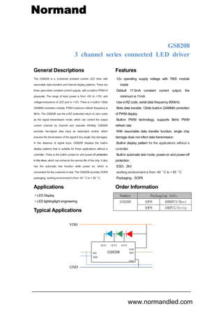
- 1. www.normandled.com Normand General Descriptions The GS8208 is a 3-channel constant current LED drive with resumable data transfers and internal display patterns. There are three open-drain constant current outputs, with a build-in PWM of grayscale. The range of input power is from +9V to +15V, and voltage-endurance of LED port is +12V. There is a built-in 12bits GAMMA correction module. PWM maximum refresh frequency is 8kHz. The GS8208 use the e-RZ (extended return to zero code) as the signal transmission mode, which can control the output current channel by channel and cascade infinitely. GS8208 provides two-signal data input as redundant control, which ensures the transmission of the signal if any single chip damages. In the absence of signal input, GS8208 displays the built-in display patterns that is suitable for those applications without a controller. There is the built-in power-on and power-off protection in the drive, which can enhance the service life of the chip. It also has the automatic test function while power on, which is convenient for the customer to test. The GS8208 provides SOP8 packaging, working environment is from -40 °C to + 85 °C. Applications ·LED Display ·LED lighting/light engineering Typical Applications Features ·12v operating supply voltage with 7805 module inside ·Default 17.5mA constant current output, the minimum is 11mA ·Use e-RZ code, serial data frequency 800kHz ·8bits data transfer, 12bits build-in GAMMA correction of PWM display ·Built-in PWM technology, supports 8kHz PWM refresh rate ·With resumable data transfer function, single chip damage does not infect data transmission ·Built-in display pattern for the applications without a controller ·Built-in automatic test mode, power-on and power-off protection ·ESD:2kV ·working environment is from -40 °C to + 85 °C ·Packaging:SOP8 Order Information Number Packaging Info. GS8208 SOP8 4000PCS/Reel SOP8 100PCS/Strip GS8208 3 channel series connected LED driver … VDH GND OUT1 OUT2 OUT3 VDH SDO GND GS8208SDI SDI2
- 2. GS8208 3 channel constant current series connected LED driver 3 channel constant current series connected LED driver Version:V0.1 Page 2 Unauthorized reproduction, duplication, use or disclosure of this document will be deemed as infringement. Block Diagram Pin Configuration Pin Configuration with LED Pin Description Pin name type Function VDH P 12V Power Supply GND P Chip Ground OUTR……OUTB OUT Constant-current outputs,connected to LED SDI IN Series data input SDI2 IN Redundant series data input SDO OUT Series data output GS8208 SDO 2 3 5 4 SDI2 GND 1 6VDH NA SDI GS8208 SDO OUTB 2 3 4 7 6 5 VDH GND SDI 1 8OUTR OUTG SDI2 VDH GND LDO Output Driver (G) Output Driver (R) 12bits PWM generator (R) 12bits PWM generator (G) OUT2 Output Driver (B) 12bits PWM generator (B) OUT3OUT1 SDI 8bits Data 12bits Data OSC current Controller PORtest Digital Processor SDO SDI2 8bits->12bits GAMMA correction Normand www.normandled.com
- 3. GS8208 3 channel constant current series connected LED driver 3 channel constant current series connected LED driver Version:V0.1 Page 3 Unauthorized reproduction, duplication, use or disclosure of this document will be deemed as infringement. Equivalent Circuits of Input and Output 1 SDI/SDI2 2 SDO 3 OUTR、OUTG、OUTB Maximum Ratings Characteristic Symbol Maximum Working Range Unit. Power Source VDH -0.4~15V V On-chip Power Source VCC -0.4~6V V Input Logic Voltage SDI -0.5~VDH+0.5 V Maximum output current IOUT 18 mA Output voltage-endurance VDS 15 V Ground current IGND 55 mA Power dissipation Pd 400 mW Working temperature TOP -40~85 o C Storage temperature Tstg -55~150 o C ESD HBM 2000 V (1)Stresses above there ratings may cause permanent damage. Exposure to absolute maximum condition for extended periods may degrade device reliability. These are stress ratings only and functional operation of the device at these or any other condition beyond those specified is not supported. (2)All voltage values are with respect to ground terminal. Normand www.normandled.com
- 4. GS8208 3 channel constant current series connected LED driver 3 channel constant current series connected LED driver Version:V0.1 Page 4 Unauthorized reproduction, duplication, use or disclosure of this document will be deemed as infringement. Electrical Characteristics Characteristic Symbol Symbol Measuring condition Min Typical Max Power supply VDH 9 12 15 V internal Power supply VCC 4 5 6 V High Input Logic Voltage VIH 4 V Low Input Logic Voltage VIL 1 V Output current IOUT VDH=12V 11 15 mA Static current Ichip 2.5 mA Power dissipation Pd 150 mW Current variation(channel) dIOUT Iout = 15mA, Vout = 1.2V ±1.5% ±3% % Current variation(chip) dIOUT2 ±3% ±6% % Current offset VS Power Source NA Voltage range of outputs VOUT 1.2 12 V External Power Res Rvdh VDH=12V 50 ohm External Power Cap Cvdh 0.1 uF Switching Characteristics Characteristic Symbol Measuring condition Min Typical Max Unit. Internal Oscillator Frequency OSC 25 MHz PWM refresh rate 8 kHz Data refresh rate 30 1017 Hz Data refresh delay time 1024 points 700 us Internal program data refresh rate 100 Hz Channel output delay time 80 ns Current output rising time 18mA, VOUT=1V 40 ns Current output falling time 40 ns PWM pulse duration 240 ns RZ data frequency 400k 800k 1M Hz Normand www.normandled.com
- 5. GS8208 3 channel constant current series connected LED driver 3 channel constant current series connected LED driver Version:V0.1 Page 5 Unauthorized reproduction, duplication, use or disclosure of this document will be deemed as infringement. Typical Application VDH GND controller OUT1 OUT2 OUT3 VDH SDO GND GS8208SDI SDI2 OUT1 OUT2 OUT3 VDH SDO GND GS8208SDI SDI2 OUT1 OUT2 OUT3 VDH SDO GND GS8208SDI SDI2 Normand www.normandled.com
- 6. GS8208 3 channel constant current series connected LED driver 3 channel constant current series connected LED driver Version:V0.1 Page 6 Unauthorized reproduction, duplication, use or disclosure of this document will be deemed as infringement. Data Format GS8208 adopts the extended return to zero code (e-RZ) data transmission mode, 8bits data for single channel, each IC supports 3 channel for display. The transmission data is filtered internally to support the data anti-jitter function. The extension type is compatible with the traditional RZ code. So it is suitable for most of the RZ code controller in the market. Single code with 1:3 duty cycle and a standard 800kHz transmission speed. The maximum frequency can reach 1MHz. GS8208 re-code the data before transmission. Data delay is less than 0.7us from chip to chip, meets the dynamic image needs. 0 code 1 code 3/4T1/4T 3/4T 1/4T T=1/800kHz <10us Intervals between code >300usReset Displaydata Ch01b7 Ch01b6 Ch01b5 Ch01b2 Ch01b1 Ch01b0 Ch00b7 Ch00b6 Ch00b5 Ch00b2 Ch00b1 Ch00b0 Ch02b7 Ch02b6 Ch02b5 Ch02b2 Ch02b1 Ch02b0 Ch(N+2)b7 Ch(N+2)b6 Ch(N+2)b5 Ch(N+2)b2 Ch(N+2)b1 Ch(N+2)b0 Ch(N+1)b7 Ch(N+1)b6 Ch(N+1)b5 Ch(N+1)b2 Ch(N+1)b1 Ch(N+1)b0 Ch(N+0)b7 Ch(N+0)b6 Ch(N+0)b5 Ch(N+0)b2 Ch(N+0)b1 Ch(N+0)b0 Reset Reset Normand www.normandled.com
- 7. GS8208 3 channel constant current series connected LED driver 3 channel constant current series connected LED driver Version:V0.1 Page 7 Unauthorized reproduction, duplication, use or disclosure of this document will be deemed as infringement. Dual channel redundant control Dual channel redundant control can be used to effectively avoid the failure of any single device damage, and reduce the damage rate of the driving system to one millionth. The SDI signal is used as the default transmission channel while the system is power on. The transmission channel priority is switched between SDI and SDI2 when the transmission data is abnormal. The device will choose the clear transmission channel after data detection. When the external control data is transmitted, SDI uses the 1-24bits received data as the display data, meanwhile, SDI2 will discard the 1-24bits data and use 25-48bits data as the display data. Data channel status testing during production In the production process, any one of the abnormal data channel will not affect display because the chip uses dual SDI input. It is difficult to detect the problem data channel during the production process, which may cause the dual channel is equivalent to a single channel. In order to avoid this situation, the status of the data channel can be detected by using the test controller in the external control situation. While any channel appears Weld, short, open or other abnormal communication, the chip will display in white to facilitate the detection of problem position. Ch24b(N+1) Ch24bN Ch24b(N-1) Ch24b2 Ch24b1 Ch24b0 Ch24bN Ch24b(N-1) Ch24b2 Ch24b1 Ch24b0 Ch24b(N-1) Ch24b2 Ch24b1 Ch24b0 SDI SDI2 SDO Normand www.normandled.com
- 8. GS8208 3 channel constant current series connected LED driver 3 channel constant current series connected LED driver Version:V0.1 Page 8 Unauthorized reproduction, duplication, use or disclosure of this document will be deemed as infringement. Working principle of the series structure LED controller It is RGB LED series structure. Power supply voltage is 12V, and the LED constant current is 18mA. Different to the parallel architecture of 5V power supply and 54mA drive current, the series architecture can provide a better drive ability. The new architecture’s total drive current is only 1/3 of the original one, and Vds=4V. The power loading ability is better. In the series structure mode, when the internal MOS paralleling with the LED is open, the current flow into the LED and the LED lights. When the internal MOS paralleling with the LED is short, the current flow into the MOS device and the LED close. Switching the MOS device by PWM signal can lights on or off the LED. Stagger output delay In order to prevent the large power interference from the LED switching, reduce the power circuit voltage fluctuations, GS8208 has a built-in output hysteresis function. OUT1, OUT2, OUT3 will work in accordance with the 80ns interval sequence, to improve the system's anti-jamming performance. Meanwhile, the current peak output stagger will reduce the system EMI radiation, to meet environmental requirements. OUT1 T 2T T=80ns OUT2 OUT3 PWM3 PWM2 PWM1 Normand www.normandled.com
- 9. GS8208 3 channel constant current series connected LED driver 3 channel constant current series connected LED driver Version:V0.1 Page 9 Unauthorized reproduction, duplication, use or disclosure of this document will be deemed as infringement. MPWM(multi-PWM) In order to increase the refresh rate of PWM output, MPWM adopts a unique method of dispersibility to distribute the periodic N in the display time, as shown in the figure below. GS8208 adopts MPWM technology, and the PWM refresh rate increases to 8kHz, which shows gentle effect and does not affect the accuracy of output current. Internal control patterns GS8208 gets into RGB test mode right after power on. If the device does not receive the external display data for a long time, the chip will go into the built-in display patterns mode. Pattern on a total of six categories of 32 series, including integral color jump, integral color gradient, meteors, waves, colorful gradient, color jump of water circulation. It is 10 minutes about, and the image refresh frequency is 100hz. Under the internal display mode, the first chip’s SDI/SDI2 needs to be connected to GND. MPWM Display Data 4 4 4 4 16 Original Display Data Normand www.normandled.com
- 10. Normand GS8208 3 channel constant current series connected LED driver 3 channel constant current series connected LED driver Version:V0.1 Page 10 Unauthorized reproduction, duplication, use or disclosure of this document will be deemed as infringement. Power dissipation When all the three output channels are turned on, the practical power dissipation is determined by the following equation: (Vout represents the output terminal voltage when the current is turned on; Duty represents the ratio of the time at which the current is turned on) ( ) 2 2 2 ... 0 0 0PD practical VccxIcc VoutA xIoutA xDutyA VoutD xIoutD xDutyD In secure operating conditions, the power consumption of an integrated chip should be less than the maximum permissible power dissipation which is determined by the package types and ambient temperature. The formula for maximum power dissipation is described as follows: )/)(( )()(max)( (max) WattCajRth CTaCTj PD The PD (max) declines as the ambient temperature rises. Therefore, suitable operating conditions should be designed with caution according to the chosen package and the ambient temperature. The following figure illustrates the relation between the maximum power dissipation and the ambient temperature of the SOP8 package. -0.1 0 0.1 0.2 0.3 0.4 0.5 0 20 40 60 80 100 120 140 160 PowerDissipationPd(W) Ambient Temperature Ta(C) Maximum Power Dissipation v.s. Ambient Temperature SOP8 www.normandled.com
- 11. GS8208 3 channel constant current series connected LED driver 3 channel constant current series connected LED driver Version:V0.1 Page 11 Unauthorized reproduction, duplication, use or disclosure of this document will be deemed as infringement. 6.000 3.910 ±0.1 4.880 4 0.406 1.270 5θ 0.535 1.450 1.600 ±0.1 0.150 ±0.05 Package Outline Dimension SOP8 0-0.076 0-0.076 0.10MAX (ENO FLASH) 0.10MAX (SIDEFLASH) ﹣θ° 1.050 ±0.1 0° 0.660 ±0.1 0.375×45° 0.203 +0.06 0.250 Normand www.normandled.com
- 12. GS8208 3 channel constant current series connected LED driver 3 channel constant current series connected LED driver Version:V0.1 Page 12 Unauthorized reproduction, duplication, use or disclosure of this document will be deemed as infringement. The products listed herein are designed for ordinary electronic application, such as electrical appliances, audio-visual equipment, communications devices and so on. Hence, it is advisable that the devices should not be used in medical instruments, surgical implants, aerospace machinery, nuclear power control system, disaster/crime-prevention equipment and the like. Misusing those products may directly or indirectly endanger human life, or cause injury and property loss. Genesis Technology will not take any responsibilities regarding the misusage of the products mentioned above. Anyone who purchases any products described herein with the above-mentioned intention or with such misused application should accept full responsibility and indemnify. Genesis Technology and his distributors and all their officers and employees shall defend jointly and severally against any and all claims and litigation and all damages, cost and expenses associated with such intention and manipulation. Normand www.normandled.com