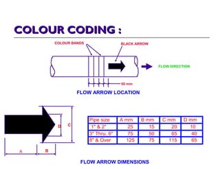
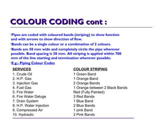
PIPING DRAWING :PIPING DRAWING :
FLOW DIAGRAM :-
Basic blueprint of the process, function & equipment
for a job (1st drawing to be completed).
Provide data to begin the design & layout of the
system.
PIPING & INSTRUMENTATION DIAGRAM
(P&ID) :-
Line Symbol & Abbreviation - easier to read. If full
name, drawing become cluttered.
Instrumentation - indicates all four major categories
of Instruments :- Temperature, Pressure, Flow &
Level.
PIPING IDENTIFICATION SYSTEMPIPING IDENTIFICATION SYSTEM
(LINE NUMBER) :(LINE NUMBER) :
Has 5 basic parts (combination of letters, numbers & symbols):-
Line Size - NPS
Conveyed Fluid (Fluid code)
Line Number - e.g.: 1006, the first 2 digit (10) is the unit area code (unit /
area 10) & the second 2 digit (06) means the line number (line 06)
Piping Classification - material classification
Insulation Type - insulation code and thickness, e.g.:
1st - Insulation for Steamtracing
Ins - Insulation for Heat Conservation
PP - Insulation for Personal Protection
3" - KE - 10 06 - C D 121 - (1st 25)
LINE SIZE
CONVEYED FLUID
(KEROSENED)
UNIT AREA
CODE
LINE INDEX
MATERIAL
CLASSIFICATION
LINE WITH STEAN TRACING
& INSULATION OF 25mm THICK
COLOUR CODING :COLOUR CODING :
COLOUR BANDS BLACK ARROW
FLOW DIRECTION
50 mm
FLOW ARROW LOCATION
FLOW ARROW DIMENSIONS
A B
CD
Pipe size A mm B mm C mm D mm
1" & 2" 25 15 20 10
3" Thru. 6" 75 50 65 40
8" & Over 125 75 115 65
COLOUR CODING cont :COLOUR CODING cont :
Pipes are coded with coloured bands (striping) to show function
and with arrows to show direction of flow.
Bands can be a single colour or a combination of 2 colours.
Bands are 50 mm wide and completely circle the pipe wherever
possible. Band spacing is 50 mm. All striping is applied within 700
mm of the line starting and termination wherever possible.
E.g.: Piping Colour Codes
SERVICES COLOUR STRIPING
1. Crude Oil 1 Green Band
2. H.P. Gas 1 Orange Band
3. Injection Gas 2 Orange Bands
4. Fuel Gas 1 Orange between 2 Black Bands
5. Fire Water Red (Fully Painted)
6. Fire Water Deluge 3 Red Bands
7. Drain System 1 Blue Band
8. H.P. Water Injection 2 Blue Bands
9. Compressed Air 1 pink Band
10. Hydraulic 2 Pink Bands

pipe fitting pnid

  • 1.
    PIPING DRAWING :PIPINGDRAWING : FLOW DIAGRAM :- Basic blueprint of the process, function & equipment for a job (1st drawing to be completed). Provide data to begin the design & layout of the system. PIPING & INSTRUMENTATION DIAGRAM (P&ID) :- Line Symbol & Abbreviation - easier to read. If full name, drawing become cluttered. Instrumentation - indicates all four major categories of Instruments :- Temperature, Pressure, Flow & Level.
  • 2.
    PIPING IDENTIFICATION SYSTEMPIPINGIDENTIFICATION SYSTEM (LINE NUMBER) :(LINE NUMBER) : Has 5 basic parts (combination of letters, numbers & symbols):- Line Size - NPS Conveyed Fluid (Fluid code) Line Number - e.g.: 1006, the first 2 digit (10) is the unit area code (unit / area 10) & the second 2 digit (06) means the line number (line 06) Piping Classification - material classification Insulation Type - insulation code and thickness, e.g.: 1st - Insulation for Steamtracing Ins - Insulation for Heat Conservation PP - Insulation for Personal Protection 3" - KE - 10 06 - C D 121 - (1st 25) LINE SIZE CONVEYED FLUID (KEROSENED) UNIT AREA CODE LINE INDEX MATERIAL CLASSIFICATION LINE WITH STEAN TRACING & INSULATION OF 25mm THICK
  • 3.
    COLOUR CODING :COLOURCODING : COLOUR BANDS BLACK ARROW FLOW DIRECTION 50 mm FLOW ARROW LOCATION FLOW ARROW DIMENSIONS A B CD Pipe size A mm B mm C mm D mm 1" & 2" 25 15 20 10 3" Thru. 6" 75 50 65 40 8" & Over 125 75 115 65
  • 4.
    COLOUR CODING cont:COLOUR CODING cont : Pipes are coded with coloured bands (striping) to show function and with arrows to show direction of flow. Bands can be a single colour or a combination of 2 colours. Bands are 50 mm wide and completely circle the pipe wherever possible. Band spacing is 50 mm. All striping is applied within 700 mm of the line starting and termination wherever possible. E.g.: Piping Colour Codes SERVICES COLOUR STRIPING 1. Crude Oil 1 Green Band 2. H.P. Gas 1 Orange Band 3. Injection Gas 2 Orange Bands 4. Fuel Gas 1 Orange between 2 Black Bands 5. Fire Water Red (Fully Painted) 6. Fire Water Deluge 3 Red Bands 7. Drain System 1 Blue Band 8. H.P. Water Injection 2 Blue Bands 9. Compressed Air 1 pink Band 10. Hydraulic 2 Pink Bands