SlideShare a Scribd company logo
1 of 12
Download to read offline
The information in this document is subject to change without notice. Before using this document, please
confirm that this is the latest version.
Not all products and/or types are available in every country. Please check with an NEC Electronics
sales representative for availability and additional information.
SINGLE POWER SUPPLY DUAL OPERATIONAL AMPLIFIERS
DATA SHEET
Document No. G17929EJ3V0DS00 (3rd edition)
Date Published December 2007 NS
Printed in Japan
2006, 2007
The mark <R> shows major revised points.
The revised points can be easily searched by copying an "<R>" in the PDF file and specifying it in the "Find what:" field.
BIPOLAR ANALOG INTEGRATED CIRCUIT
μPC1251GR-9LG, μPC1251MP-KAA, μPC358GR-9LG
DESCRIPTION
The μ PC1251GR-9LG, μ PC1251MP-KAA, μ PC358GR-9LG are dual operational amplifiers which are designed to
operate for a single power supply. It includes features of low-voltage operation, a common-mode input voltage that
range from V−
(GND) level, an output from a V−
(GND) level that is determined by the output stage of class C push-
pull circuit and a 50 μA(TYP.) constant current, and a low current consumption.
In addition, this can operate at both positive and negative power supply and it can be extensively used in various
amplifier circuits.
The μ PC1251GR-9LG, μ PC1251MP-KAA which expands temperature type is suited for wide operating ambient
temperature use, and μPC358GR-9LG is used for general purposes.
A DC parameter selection that is compatible to operational amplifiers is also available.
μ PC451GR-9LG, μ PC324GR-9LG which are quad types with the same circuit configuration are also available as
series of operational amplifiers.
FEATURES
• Input Offset Voltage ±2 mV (TYP.) • Internal frequency compensation
• Input Offset Current ±5 nA (TYP.) • Output short-circuit protection
• Large Signal Voltage Gain 100000 (TYP.)
• Small Package
The mounting area is reduced to 40% or 66% compared to the conventional 8-pin plastic SOP as shown in the
following diagram.
Package Standard SOP TSSOP TSSOP (2.8 x 2.9)
Subject part number μ PC1251G2,
μ PC358G2
μ PC1251GR-9LG,
μ PC358GR-9LG
μ PC1251MP-KAA
Outline comparison
5.2
6.5 4.4
6.4
3.15
4.02.8
2.9
(Mounting area ratio) (100%) (60%) (34%)
<R>
<R>
www.datasheet4u.com
Data Sheet G17929EJ3V0DS2
μPC1251GR-9LG, μPC1251MP-KAA, μPC358GR-9LG
ORDERING INFORMATION
Part Number Selected Grade Package Package Type
μ PC1251GR-9LG-E1-A
Note
Standard 8-pin plastic TSSOP (5.72 mm(225)) • 12 mm wide embossed taping
• Pin 1 on draw-out side
μ PC1251GR-9LG-E2-A
Note
Standard 8-pin plastic TSSOP (5.72 mm(225)) • 12 mm wide embossed taping
• Pin 1 at take-up side
μ PC1251GR(5)-9LG-E1-A
Note
DC
parameter selection
8-pin plastic TSSOP (5.72 mm(225)) • 12 mm wide embossed taping
• Pin 1 on draw-out side
μ PC1251GR(5)-9LG-E2-A
Note
DC
parameter selection
8-pin plastic TSSOP (5.72 mm(225)) • 12 mm wide embossed taping
• Pin 1 at take-up side
μ PC1251MP-KAA-E1-A
Note
Standard 8-pin plastic TSSOP (2.8 x 2.9) • 12 mm wide embossed taping
• Pin 1 on draw-out side
μ PC1251MP-KAA-E2-A
Note
Standard 8-pin plastic TSSOP (2.8 x 2.9) • 12 mm wide embossed taping
• Pin 1 at take-up side
μ PC1251MP(5)-KAA-E1-A
Note
DC
parameter selection
8-pin plastic TSSOP (2.8 x 2.9) • 12 mm wide embossed taping
• Pin 1 on draw-out side
μ PC1251MP(5)-KAA-E2-A
Note
DC
parameter selection
8-pin plastic TSSOP (2.8 x 2.9) • 12 mm wide embossed taping
• Pin 1 at take-up side
μ PC358GR-9LG-E1-A
Note
Standard 8-pin plastic TSSOP(5.72 mm(225)) • 12 mm wide embossed taping
• Pin 1 on draw-out side
μ PC358GR-9LG-E2-A
Note
Standard 8-pin plastic TSSOP(5.72 mm(225)) • 12 mm wide embossed taping
• Pin 1 at take-up side
μ PC358GR(5)-9LG-E1-A
Note
DC
parameter selection
8-pin plastic TSSOP(5.72 mm(225)) • 12 mm wide embossed taping
• Pin 1 on draw-out side
μ PC358GR(5)-9LG-E2-A
Note
DC
parameter selection
8-pin plastic TSSOP(5.72 mm(225)) • 12 mm wide embossed taping
• Pin 1 at take-up side
Note Pb-free (This product does not contain Pb in the external electrode and other parts.)
<R>
www.datasheet4u.com
Data Sheet G17929EJ3V0DS 3
μPC1251GR-9LG, μPC1251MP-KAA, μPC358GR-9LG
EQUIVALENT CIRCUIT (1/2 Circuit) PIN CONFIGURATION (Marking side)
Q6
Q5
Q7
Q13
OUT
V−
V+
6 A
CC
Q4
Q3Q2
Q1
Q8 Q9
Q12
Q11
Q10
IN
II
RSC
6 A
100 A
50 A
μ μ
μ
μ
+
−
OUT1
IN1
V−
V+
OUT2
II2
IN2
1
2
3
4
8
7
6
5
II1
1
+−
2
−+
ABSOLUTE MAXIMUM RATINGS (TA = 25°C)
Parameter Symbol μ PC1251GR-9LG,
μ PC1251GR(5)-9LG
μ PC1251MP-KAA,
μ PC1251MP(5)-KAA
μ PC358GR-9LG,
μ PC358GR(5)-9LG
Unit
Voltage between V
+
and V
− Note1
V
+
− V
−
−0.3 to +32 V
Differential Input Voltage VID ±32 V
Input Voltage
Note2
VI V
−
− 0.3 to V
−
+ 32 V
Output applied Voltage
Note3
VO V
−
− 0.3 to V
+
+ 0.3 V
Total Power Dissipation
Note4
PT 440 mW
Output Short Circuit Duration
Note5
tS Indefinite s
Operating Ambient Temperature TA −40 to +125 −40 to +85 °C
Storage Temperature Tstg −55 to +150 −55 to +125 °C
Note1. Note that reverse connections of the power supply may damage ICs.
2. The input voltage is allowed to input without damage or destruction independent of the magnitude of V
+
. Either
input signal is not allowed to go negative by more than 0.3 V. In addition, the input voltage that operates
normally as an operational amplifier is within the Common Mode Input Voltage range of an electrical
characteristic.
3. A range where input voltage can be applied to an output pin externally with no deterioration or damage to the
feature (characteristic). The input voltage can be applied regardless of the electric supply voltage. This
specification which includes the transition state such as electric power ON/OFF must be kept.
4. This is the value of when the glass epoxy substrate (size: 100 mm x 100 mm, thickness: 1 mm, 15% of the
substrate area where only one side is copper foiled is filling wired) is mounted.
Note that restrictions will be made to the following conditions for each product, and the derating ratio
depending on the operating ambient temperature.
μPC1251GR-9LG: Derate at −5.5 mW/°C when TA > 69°C.
(Junction − ambient thermal resistance Rth(J-A) = 183°C/W)
μPC1251MP-KAA: Derate at −4.8 mW/°C when TA > 58°C.
(Junction − ambient thermal resistance Rth(J-A) = 208°C/W)
μPC358GR-9LG: Derate at −5.5 mW/°C when TA > 44°C.
(Junction − ambient thermal resistance Rth(J-A) = 183°C/W)
5. Short circuits from the output to V
+
can cause destruction. Pay careful attention to the total power dissipation
not to exceed the absolute maximum ratings, Note 4.
<R>
<R>
www.datasheet4u.com
Data Sheet G17929EJ3V0DS4
μPC1251GR-9LG, μPC1251MP-KAA, μPC358GR-9LG
RECOMMENDED OPERATING CONDITIONS
Parameter Symbol MIN. TYP. MAX. Unit
Power Supply Voltage (Split) V
±
±1.5 ±15 V
Power Supply Voltage (V
−
= GND) V
+
+3 +30 V
ELECTRICAL CHARACTERISTICS
μPC1251GR-9LG, μPC1251MP-KAA, μPC358GR-9LG (TA = 25°C, V+
= +5 V, V−
= GND)
Parameter Symbol Conditions MIN. TYP. MAX. Unit
Input Offset Voltage VIO RS = 0 Ω ±2 ±7 mV
Input Offset Current IIO ±5 ±50 nA
Input Bias Current
Note1
IB 14 250 nA
Large Signal Voltage Gain AV RL ≥ 2 kΩ 25000 100000
Circuit Current
Note2
ICC RL = ∞, IO = 0 A 0.7 1.2 mA
Common Mode Rejection Ratio CMR 65 70 dB
Supply Voltage Rejection Ratio SVR 65 100 dB
Output Voltage Swing VO RL = 2 kΩ (Connect to GND) 0 V
+
− 1.5 V
Common Mode lnput Voltage Range VICM 0 V
+
− 1.5 V
Output Source Current IO SOURCE VIN (+) = +1 V, VIN (−) = 0 V 20 40 mA
Output Sink Current IO SINK1 VIN (−) = +1 V, VIN (+) = 0 V 10 20 mA
IO SINK2 VIN (−) = +1 V, VIN (+) = 0 V, VO = 200 mV 12 50 μA
Channel Separation f = 1 to 20 kHz 120 dB
μPC1251GR(5)-9LG, μPC1251MP(5)-KAA, μPC358GR(5)-9LG (TA = 25°C, V+
= +5 V, V−
= GND)
Parameter Symbol Conditions MIN. TYP. MAX. Unit
Input Offset Voltage VIO RS = 0 Ω ±2 ±3 mV
Input Offset Current IIO ±5 ±50 nA
Input Bias Current
Note1
IB 14 60 nA
Large Signal Voltage Gain AV RL ≥ 2 kΩ 50000 100000
Circuit Current
Note2
ICC RL = ∞, IO = 0 A 0.7 0.9 mA
Common Mode Rejection Ratio CMR 65 70 dB
Supply Voltage Rejection Ratio SVR 65 100 dB
Output Voltage Swing VO RL = 2 kΩ (Connect to GND) 0 V
+
− 1.5 V
Common Mode lnput Voltage Range VICM 0 V
+
− 1.4 V
Output Source Current IO SOURCE VIN (+) = +1 V, VIN (−) = 0 V 30 40 mA
Output Sink Current IO SINK1 VIN (−) = +1 V, VIN (+) = 0 V 15 20 mA
IO SINK2 VIN (−) = +1 V, VIN (+) = 0 V, VO = 200 mV 30 50 70 μA
Channel Separation f = 1 to 20 kHz 120 dB
Notes1. The input bias current flows in the direction where the IC flows out because the first stage is configured with a
PNP transistor.
2. This is a current that flows in the internal circuit. This current will flow irrespective of the channel used.
<R>www.datasheet4u.com
Data Sheet G17929EJ3V0DS 5
μPC1251GR-9LG, μPC1251MP-KAA, μPC358GR-9LG
TYPICAL PERFORMANCE CHARACTERISTICS (TA = 25°C, TYP.) (Reference value)
PT vs. TA ICC vs. V+
PT-TotalPowerDissipation-mW
600
500
400
300
200
100
0
0 20 40 60 80 100 120 140
μPC358G
R-9LG
μ
PC
1251G
R
-9LG
μPC1251M
P-KAAWith 100 mm x 100 mm,
thickness 1 mm glass epoxy
substrate (refer to "ABSOLUTE
MAXIMUM RATINGS Note 4" )
TA - Operating Ambient Temperature - °C
ICC-SupplyCurrent-mA
0
0.5
1
1.5
2
0 10 20 30 40
RL = ∞
IO = 0 A
TA = 25°C
125°C
−40°C
V+
- Power Supply Voltage - V (V−
= GND)
VIO vs. V+
VIO vs. TA
VIO-InputOffsetVoltage-mV
0 10 20 30 40
3
2
1
0
-1
-2
-3
V+
- Power Supply Voltage - V (V−
= GND)
VIO-InputOffsetVoltage-mV
-3
-2
-1
0
1
2
3
-50 0 50 100 150
V+
= +5 V, V−
= GND
each 5 samples data
TA - Operating Ambient Temperature - °C
IB vs. V+
IB vs. TA
IB-InputBiasCurrent-nA
0
10
20
30
0 10 20 30 40
V+
- Power Supply Voltage - V (V−
= GND)
IB-InputBiasCurrent-nA
0
10
20
30
-50 0 50 100 150
V+
= +15 V
V−
= GND
TA - Operating Ambient Temperature - °C
<R>
www.datasheet4u.com
Data Sheet G17929EJ3V0DS6
μPC1251GR-9LG, μPC1251MP-KAA, μPC358GR-9LG
IO SHORT vs. TA AV vs. V+IOSHORT-OutputShortCurrent-mA
-20 0 20 40 60 80
30
40
50
60
70
−
+
IO SHORT
TA - Operating Ambient Temperature - °C
AV-VoltageGain-dB
160
0 40
120
80
40
0
302010
RL = 20 kΩ
2 kΩ
V+
- Power Supply Voltage - V (V−
= GND)
AV, φ vs. f
AV-VoltageGain-dB,φ-PhaseMargin-deg.
140
120
100
80
60
40
20
0
V = ±15 V±
±7.5 V
±2.5 V
±15 V
±7.5 V
±2.5 V
AV
φ
f - Frequency - Hz
VO vs. f CMR vs. f
VO-OutputVoltageSignal-Vp-p
20
1 k
15
10
5
0
3 5 10 k 30 50 100 k 3005001 M
−
+
+15 V
VO
VIN
100 kΩ
1 kΩ
+7 V
2 kΩ
f - Frequency - Hz
CMR-CommonModeRejectionRatio-dB
120
100 1 k 1 M
100
80
60
40
20
10 k 100 k
0
f - Frequency - Hz
0.1 1 10 100 1 k 10 k 100 k 1 M
www.datasheet4u.com
Data Sheet G17929EJ3V0DS 7
μPC1251GR-9LG, μPC1251MP-KAA, μPC358GR-9LG
PULSE RESPONSE SR - TA
VIN-InputVoltage-VVO-OutputVoltage-V
4
0
3
2
1
0
3
2
1
20 40 60 80
RL ≥ 2 kΩ
V = +15 V+
t - time - μs
SR-SlewRate-V/μs
-50 0 50 100
V = ±15 V±
VO = ±10 V
0.4
0.3
0.2
0.1
0
SR−
SR+
TA - Operating Ambient Temperature - °C
VO vs. IO SINK ΔVO vs. IO SOURCE
VO-OutputVoltage-V
0.01
0.1
1
10
0.01 0.1 1 10 100
V+
= +15 V
V /2+
V+
VO
IO SINK
−
+
TA = −40°C
25°C
125°C
IO SINK - Output Sink Current - mA
ΔVO-OutputVoltagetoV+
-V
0
1
2
3
4
5
0.01 0.1 1 10 100
TA = −40°C
25°C
125°C
V /2+
V+
ΔVO
IO SOURCE
+
−
IO SOURCE - Output Source Current - mA
www.datasheet4u.com
Data Sheet G17929EJ3V0DS8
μPC1251GR-9LG, μPC1251MP-KAA, μPC358GR-9LG
PRECAUTIONS FOR USE
O The process of unused circuits
If there is an unused circuit, the following connection is recommended.
Process example of unused circuits
V+
V−
V+
V−
R
R
−
+
To potentials within the range of
common-mode input voltage (VICM)
Remark A midpoint potential of V+
and V−
is applied to this example.
O Ratings of input/output pin voltage
When the voltage of input/output pin exceeds the absolute maximum rating, it may cause degradation of
characteristics or damages, by a conduction of a parasitic diode within an IC. In addition, when the input pin may be
lower than V−
, or the output pin may exceed the power supply voltage, it is recommended to make a clump circuit by
a diode whose forward voltage is low (e.g.: Schottky diode) for protection.
O Range of common-mode input voltage
When the supply voltage does not meet the condition of electrical characteristics, the range of common-mode
input voltage is as follows.
VICM (TYP.): V−
to V+
− 1.5 (V) (TA = 25°C)
During designing, temperature characteristics for use with allowance.
O The maximum output voltage
The range of the TYP. value of the maximum output voltage when the supply voltage does not meet the condition
of electrical characteristics is as follows:
VOm
+
(TYP.): V+
− 1.5 (V) (TA = 25°C), VOm
−
(TYP.) (IO SINK ≤ 50 μA): Approx. V−
(V) (TA = 25°C)
During designing, consider variations in characteristics and temperature characteristics for use with allowance.
In addition, also note that the output voltage range (VOm
+
− VOm
−
) becomes narrow when an output current
increases.
O Operation of output
This IC consist an output level of a class C push-pull. Therefore, when a load resistance is connected to the
midpoint potential of V+
, V−
, a crossover distortion occurs at the transition state of output current flow direction
(source, sink).
O Handling of ICs
When stress is added to ICs due to warpage or bending of a board, the characteristic fluctuates due to
piezoelectric effect. Therefore, pay attention to warpage or bending of a board.
<R>
www.datasheet4u.com
Data Sheet G17929EJ3V0DS 9
μPC1251GR-9LG, μPC1251MP-KAA, μPC358GR-9LG
PACKAGE DRAWINGS (Unit: mm)
Sy
e
Sxb M
θ L
c
Lp
D
HE
ZD
A1
A2
A
D1
E
A3
S
0.145±0.055
(UNIT:mm)
ITEM DIMENSIONS
D
D1
E
HE
A
A1
A2
A3
3.15±0.15
3.00±0.10
4.40±0.10
6.40±0.20
1.20 MAX.
0.10±0.05
1.00±0.05
0.25
c
θ
e
x
y
ZD
0.65
0.10
0.10
0.60
L
Lp
L1
0.50
0.60±0.15
1.00±0.20
P8GR-65-9LG
3°+5°
−3°
NOTE
Each lead centerline is located within 0.10mm of
its true position at maximum material condition.
detail of lead end
8-PIN PLASTIC TSSOP (5.72mm (225))
0.24b
4
5
1
8
L1
+0.06
−0.05
www.datasheet4u.com
Data Sheet G17929EJ3V0DS10
μPC1251GR-9LG, μPC1251MP-KAA, μPC358GR-9LG
58
1
M
S
S S
8-PIN PLASTIC TSSOP(2.8x2.9)
detail of lead end
ITEM DIMENSIONS
D
D1
E
e
A1
A
A2
L1
ZD
c
x
y
b
2.80
0.08
+
+
1.03 MAX.
0.85
4.00
±
±0.60
0.525
0.20
0.05
0.03
0.05
±0.10
±
±
±
±
0.05
0.145
0.10
0.10
0.22 0.05
Lp 0.37
A3
3°
5°
3°
(UNIT:mm)
P8MP-65-KAA
D
D1
L1
A
A2
A1
ZD
e
b
y
Lp
θ
HE
c
A3
x 2.90
3.00 0.20
0.20
4
NEC Electronics Corporation 2006
S
0.65
0.25
HE
E
NOTE
Each lead centerline is located within 0.10 mm of
its true position at maximum material condition.
<R>
www.datasheet4u.com
Data Sheet G17929EJ3V0DS 11
μPC1251GR-9LG, μPC1251MP-KAA, μPC358GR-9LG
RECOMMENDED SOLDERING CONDITIONS
The μ PC1251GR-9LG, μ PC1251MP-KAA, μ PC358GR-9LG should be soldered and mounted under the
following recommended conditions.
For soldering methods and conditions other than those recommended below, contact an NEC Electronics sales
representative.
For technical information, see the following website.
Semiconductor Device Mount Manual (http://www.necel.com/pkg/en/mount/index.html)
Type of Surface Mount Device
μPC1251GR-9LG-A
Note
, μPC1251GR(5)-9LG-A
Note
,
μPC358GR-9LG-A
Note
, μPC358GR(5)-9LG-A
Note
: 8-pin plastic TSSOP (5.72 mm (225))
μPC1251MP-KAA-A
Note
, μPC1251MP(5)-KAA-A
Note
: 8-pin plastic TSSOP (2.8 x 2.9)
Process Conditions Symbol
Infrared ray reflow Peak temperature: 260°C, Reflow time: 60 seconds or less (at 220°C or higher),
Maximum number of reflow processes: 3 times.
IR60-00-3
Wave soldering Solder temperature: 260°C or below, Flow time: 10 seconds or less, Maximum
number of flow processes: 1 time,
Pre-heating temperature: 120°C or below (Package surface temperature).
WS60-00-1
Partial heating method Pin temperature: 350°C or below,
Heat time: 3 seconds or less (Per each side of the device).
P350
Note Pb-free (This product does not contain Pb in external electrode and other parts.)
Caution Apply only one kind of soldering condition to a device, except for “partial heating method”, or the
device will be damaged by heat stress.
Remark Flux: Rosin flux with low chlorine (0.2 Wt% or below) recommended.
REFERENCE DOCUMENTS
Document Name Document No.
QUALITY GRADES ON NEC SEMICONDUCTOR DEVICES C11531E
SEMICONDUCTOR DEVICE MOUNT MANUAL http://www.necel.com/pkg/en/mount/index.html
NEC SEMICONDUCTOR DEVICE RELIABILITY/QUALITY CONTROL
SYSTEM-STANDARD LINEAR IC
IEI-1212
REVIEW OF QUALITY AND RELIABILITY HANDBOOK C12769E
NEC SEMICONDUCTOR DEVICE RELIBIALITY/QUALITY CONTROL
SYSTEM
C10983E
<R>
<R>
www.datasheet4u.com
μPC1251GR-9LG, μPC1251MP-KAA, μPC358GR-9LG
The information in this document is current as of December, 2007. The information is subject to
change without notice. For actual design-in, refer to the latest publications of NEC Electronics data
sheets or data books, etc., for the most up-to-date specifications of NEC Electronics products. Not
all products and/or types are available in every country. Please check with an NEC Electronics sales
representative for availability and additional information.
No part of this document may be copied or reproduced in any form or by any means without the prior
written consent of NEC Electronics. NEC Electronics assumes no responsibility for any errors that may
appear in this document.
NEC Electronics does not assume any liability for infringement of patents, copyrights or other intellectual
property rights of third parties by or arising from the use of NEC Electronics products listed in this document
or any other liability arising from the use of such products. No license, express, implied or otherwise, is
granted under any patents, copyrights or other intellectual property rights of NEC Electronics or others.
Descriptions of circuits, software and other related information in this document are provided for illustrative
purposes in semiconductor product operation and application examples. The incorporation of these
circuits, software and information in the design of a customer's equipment shall be done under the full
responsibility of the customer. NEC Electronics assumes no responsibility for any losses incurred by
customers or third parties arising from the use of these circuits, software and information.
While NEC Electronics endeavors to enhance the quality, reliability and safety of NEC Electronics products,
customers agree and acknowledge that the possibility of defects thereof cannot be eliminated entirely. To
minimize risks of damage to property or injury (including death) to persons arising from defects in NEC
Electronics products, customers must incorporate sufficient safety measures in their design, such as
redundancy, fire-containment and anti-failure features.
NEC Electronics products are classified into the following three quality grades: "Standard", "Special" and
"Specific".
The "Specific" quality grade applies only to NEC Electronics products developed based on a customer-
designated "quality assurance program" for a specific application. The recommended applications of an NEC
Electronics product depend on its quality grade, as indicated below. Customers must check the quality grade of
each NEC Electronics product before using it in a particular application.
The quality grade of NEC Electronics products is "Standard" unless otherwise expressly specified in NEC
Electronics data sheets or data books, etc. If customers wish to use NEC Electronics products in applications
not intended by NEC Electronics, they must contact an NEC Electronics sales representative in advance to
determine NEC Electronics' willingness to support a given application.
(Note)
•
•
•
•
•
•
M8E 02. 11-1
(1)
(2)
"NEC Electronics" as used in this statement means NEC Electronics Corporation and also includes its
majority-owned subsidiaries.
"NEC Electronics products" means any product developed or manufactured by or for NEC Electronics (as
defined above).
Computers, office equipment, communications equipment, test and measurement equipment, audio
and visual equipment, home electronic appliances, machine tools, personal electronic equipment
and industrial robots.
Transportation equipment (automobiles, trains, ships, etc.), traffic control systems, anti-disaster
systems, anti-crime systems, safety equipment and medical equipment (not specifically designed
for life support).
Aircraft, aerospace equipment, submersible repeaters, nuclear reactor control systems, life
support systems and medical equipment for life support, etc.
"Standard":
"Special":
"Specific":
www.datasheet4u.com

More Related Content

What's hot

Original N-channel 650 V 0.230 Ohm 12 A MDmesh V Power MOSFET in DPAK DPAK ST...
Original N-channel 650 V 0.230 Ohm 12 A MDmesh V Power MOSFET in DPAK DPAK ST...Original N-channel 650 V 0.230 Ohm 12 A MDmesh V Power MOSFET in DPAK DPAK ST...
Original N-channel 650 V 0.230 Ohm 12 A MDmesh V Power MOSFET in DPAK DPAK ST...AUTHELECTRONIC
 
Original Mosfet13N60M2 13N60 STF13N60M2 11A 650V TO-220 New
Original Mosfet13N60M2 13N60 STF13N60M2 11A 650V TO-220 NewOriginal Mosfet13N60M2 13N60 STF13N60M2 11A 650V TO-220 New
Original Mosfet13N60M2 13N60 STF13N60M2 11A 650V TO-220 NewAUTHELECTRONIC
 
Av02 3563 en-ds_acpl-c87x_04mar2013-2
Av02 3563 en-ds_acpl-c87x_04mar2013-2Av02 3563 en-ds_acpl-c87x_04mar2013-2
Av02 3563 en-ds_acpl-c87x_04mar2013-2srinivasponnaluri
 
Datasheet.hk p55nf06l 4218782
Datasheet.hk p55nf06l 4218782Datasheet.hk p55nf06l 4218782
Datasheet.hk p55nf06l 4218782Edson Silva
 
Origianl Opto TLP781 P781 PC781 781 DIP-4 New
Origianl Opto TLP781 P781 PC781 781 DIP-4 NewOrigianl Opto TLP781 P781 PC781 781 DIP-4 New
Origianl Opto TLP781 P781 PC781 781 DIP-4 NewAUTHELECTRONIC
 
Original PNP Transistors PZT2907A PZT2907 2907 P2F SOT22-3 New On Semiconductor
Original PNP Transistors PZT2907A PZT2907 2907 P2F SOT22-3 New On SemiconductorOriginal PNP Transistors PZT2907A PZT2907 2907 P2F SOT22-3 New On Semiconductor
Original PNP Transistors PZT2907A PZT2907 2907 P2F SOT22-3 New On Semiconductorauthelectroniccom
 
Bta08 600 bw3-d tiristor bidireccional
Bta08 600 bw3-d  tiristor bidireccionalBta08 600 bw3-d  tiristor bidireccional
Bta08 600 bw3-d tiristor bidireccional8525
 
Original N-Channel Mosfet DN2540 DN2540N5 2540 TO-220 New Supertex
Original N-Channel Mosfet DN2540 DN2540N5 2540 TO-220 New SupertexOriginal N-Channel Mosfet DN2540 DN2540N5 2540 TO-220 New Supertex
Original N-Channel Mosfet DN2540 DN2540N5 2540 TO-220 New SupertexAUTHELECTRONIC
 
Original Switch Power Supply IC FSL136MR 136MR 136 DIP-8 New FairChild
Original Switch Power Supply IC FSL136MR 136MR 136 DIP-8 New FairChildOriginal Switch Power Supply IC FSL136MR 136MR 136 DIP-8 New FairChild
Original Switch Power Supply IC FSL136MR 136MR 136 DIP-8 New FairChildAUTHELECTRONIC
 
Original P-Channel Mosfet IRFR5305TRPBF FR5305 5305 FR530S 55V 31A TO-252 New IR
Original P-Channel Mosfet IRFR5305TRPBF FR5305 5305 FR530S 55V 31A TO-252 New IROriginal P-Channel Mosfet IRFR5305TRPBF FR5305 5305 FR530S 55V 31A TO-252 New IR
Original P-Channel Mosfet IRFR5305TRPBF FR5305 5305 FR530S 55V 31A TO-252 New IRAUTHELECTRONIC
 
Original Zener Diode 1N5366B 5366B 5366 5W 39V New
Original Zener Diode 1N5366B 5366B 5366 5W 39V NewOriginal Zener Diode 1N5366B 5366B 5366 5W 39V New
Original Zener Diode 1N5366B 5366B 5366 5W 39V NewAUTHELECTRONIC
 
Ldr1833 - datasheet - st microelectronics
Ldr1833 -  datasheet - st microelectronicsLdr1833 -  datasheet - st microelectronics
Ldr1833 - datasheet - st microelectronicsMarioFarias18
 
As built and proposed SLD
As built and proposed SLDAs built and proposed SLD
As built and proposed SLDQasim Muhammad
 

What's hot (20)

Original N-channel 650 V 0.230 Ohm 12 A MDmesh V Power MOSFET in DPAK DPAK ST...
Original N-channel 650 V 0.230 Ohm 12 A MDmesh V Power MOSFET in DPAK DPAK ST...Original N-channel 650 V 0.230 Ohm 12 A MDmesh V Power MOSFET in DPAK DPAK ST...
Original N-channel 650 V 0.230 Ohm 12 A MDmesh V Power MOSFET in DPAK DPAK ST...
 
Original Mosfet13N60M2 13N60 STF13N60M2 11A 650V TO-220 New
Original Mosfet13N60M2 13N60 STF13N60M2 11A 650V TO-220 NewOriginal Mosfet13N60M2 13N60 STF13N60M2 11A 650V TO-220 New
Original Mosfet13N60M2 13N60 STF13N60M2 11A 650V TO-220 New
 
TRANSISTORES
TRANSISTORESTRANSISTORES
TRANSISTORES
 
Av02 3563 en-ds_acpl-c87x_04mar2013-2
Av02 3563 en-ds_acpl-c87x_04mar2013-2Av02 3563 en-ds_acpl-c87x_04mar2013-2
Av02 3563 en-ds_acpl-c87x_04mar2013-2
 
Sbos078
Sbos078Sbos078
Sbos078
 
Datasheet.hk p55nf06l 4218782
Datasheet.hk p55nf06l 4218782Datasheet.hk p55nf06l 4218782
Datasheet.hk p55nf06l 4218782
 
Origianl Opto TLP781 P781 PC781 781 DIP-4 New
Origianl Opto TLP781 P781 PC781 781 DIP-4 NewOrigianl Opto TLP781 P781 PC781 781 DIP-4 New
Origianl Opto TLP781 P781 PC781 781 DIP-4 New
 
PTC31 - PTP31
PTC31 - PTP31PTC31 - PTP31
PTC31 - PTP31
 
Original PNP Transistors PZT2907A PZT2907 2907 P2F SOT22-3 New On Semiconductor
Original PNP Transistors PZT2907A PZT2907 2907 P2F SOT22-3 New On SemiconductorOriginal PNP Transistors PZT2907A PZT2907 2907 P2F SOT22-3 New On Semiconductor
Original PNP Transistors PZT2907A PZT2907 2907 P2F SOT22-3 New On Semiconductor
 
Mrf1535 t1
Mrf1535 t1Mrf1535 t1
Mrf1535 t1
 
Bta08 600 bw3-d tiristor bidireccional
Bta08 600 bw3-d  tiristor bidireccionalBta08 600 bw3-d  tiristor bidireccional
Bta08 600 bw3-d tiristor bidireccional
 
Datasheet
DatasheetDatasheet
Datasheet
 
Original N-Channel Mosfet DN2540 DN2540N5 2540 TO-220 New Supertex
Original N-Channel Mosfet DN2540 DN2540N5 2540 TO-220 New SupertexOriginal N-Channel Mosfet DN2540 DN2540N5 2540 TO-220 New Supertex
Original N-Channel Mosfet DN2540 DN2540N5 2540 TO-220 New Supertex
 
Original Switch Power Supply IC FSL136MR 136MR 136 DIP-8 New FairChild
Original Switch Power Supply IC FSL136MR 136MR 136 DIP-8 New FairChildOriginal Switch Power Supply IC FSL136MR 136MR 136 DIP-8 New FairChild
Original Switch Power Supply IC FSL136MR 136MR 136 DIP-8 New FairChild
 
Original P-Channel Mosfet IRFR5305TRPBF FR5305 5305 FR530S 55V 31A TO-252 New IR
Original P-Channel Mosfet IRFR5305TRPBF FR5305 5305 FR530S 55V 31A TO-252 New IROriginal P-Channel Mosfet IRFR5305TRPBF FR5305 5305 FR530S 55V 31A TO-252 New IR
Original P-Channel Mosfet IRFR5305TRPBF FR5305 5305 FR530S 55V 31A TO-252 New IR
 
Piezo switch
Piezo switchPiezo switch
Piezo switch
 
Original Zener Diode 1N5366B 5366B 5366 5W 39V New
Original Zener Diode 1N5366B 5366B 5366 5W 39V NewOriginal Zener Diode 1N5366B 5366B 5366 5W 39V New
Original Zener Diode 1N5366B 5366B 5366 5W 39V New
 
Ldr1833 - datasheet - st microelectronics
Ldr1833 -  datasheet - st microelectronicsLdr1833 -  datasheet - st microelectronics
Ldr1833 - datasheet - st microelectronics
 
Iwatsu bh analyzer_catalog_denkei
Iwatsu bh analyzer_catalog_denkeiIwatsu bh analyzer_catalog_denkei
Iwatsu bh analyzer_catalog_denkei
 
As built and proposed SLD
As built and proposed SLDAs built and proposed SLD
As built and proposed SLD
 

Similar to C1251 nec

BOOST110.pdf
BOOST110.pdfBOOST110.pdf
BOOST110.pdftahar6
 
Original NPN Transistor MJD44H11T4G 4H11G TO-252 New ON Semiconductor
Original NPN Transistor MJD44H11T4G 4H11G TO-252 New ON SemiconductorOriginal NPN Transistor MJD44H11T4G 4H11G TO-252 New ON Semiconductor
Original NPN Transistor MJD44H11T4G 4H11G TO-252 New ON Semiconductorauthelectroniccom
 
Original PNP Transistor MJD45H11T4G 5H11G TO-252 New ON Semiconductor
Original PNP Transistor MJD45H11T4G 5H11G TO-252 New ON SemiconductorOriginal PNP Transistor MJD45H11T4G 5H11G TO-252 New ON Semiconductor
Original PNP Transistor MJD45H11T4G 5H11G TO-252 New ON Semiconductorauthelectroniccom
 
TDA8566(1).pdf
TDA8566(1).pdfTDA8566(1).pdf
TDA8566(1).pdfivan ion
 
Emmvee Crystal Off-grid Module:
Emmvee Crystal Off-grid Module:Emmvee Crystal Off-grid Module:
Emmvee Crystal Off-grid Module:Emmvee India
 
Advanced motion controls az60a8ddc
Advanced motion controls az60a8ddcAdvanced motion controls az60a8ddc
Advanced motion controls az60a8ddcElectromate
 
Tda8566(1)
Tda8566(1)Tda8566(1)
Tda8566(1)ivan ion
 
Advanced motion controls az20a8i
Advanced motion controls az20a8iAdvanced motion controls az20a8i
Advanced motion controls az20a8iElectromate
 
Advanced motion controls az20a8i final
Advanced motion controls az20a8i finalAdvanced motion controls az20a8i final
Advanced motion controls az20a8i finalElectromate
 
Advanced motion controls azxbdc15a8
Advanced motion controls azxbdc15a8Advanced motion controls azxbdc15a8
Advanced motion controls azxbdc15a8Electromate
 
QSFP28-100G-SR4-T01#111001.pdf
QSFP28-100G-SR4-T01#111001.pdfQSFP28-100G-SR4-T01#111001.pdf
QSFP28-100G-SR4-T01#111001.pdfGLsun Mall
 
qsfp28-100g-sr4-850nm-100m-optical-transceiver-111001.pdf
qsfp28-100g-sr4-850nm-100m-optical-transceiver-111001.pdfqsfp28-100g-sr4-850nm-100m-optical-transceiver-111001.pdf
qsfp28-100g-sr4-850nm-100m-optical-transceiver-111001.pdfGLsun Mall
 
qsfp28-100g-sr4-850nm-100m-optical-transceiver-111001.pdf
qsfp28-100g-sr4-850nm-100m-optical-transceiver-111001.pdfqsfp28-100g-sr4-850nm-100m-optical-transceiver-111001.pdf
qsfp28-100g-sr4-850nm-100m-optical-transceiver-111001.pdfGLsun Mall
 
Advanced motion controls az40a8ddc
Advanced motion controls az40a8ddcAdvanced motion controls az40a8ddc
Advanced motion controls az40a8ddcElectromate
 
Lm7805
Lm7805Lm7805
Lm7805tyhfre
 

Similar to C1251 nec (20)

BOOST110.pdf
BOOST110.pdfBOOST110.pdf
BOOST110.pdf
 
Original NPN Transistor MJD44H11T4G 4H11G TO-252 New ON Semiconductor
Original NPN Transistor MJD44H11T4G 4H11G TO-252 New ON SemiconductorOriginal NPN Transistor MJD44H11T4G 4H11G TO-252 New ON Semiconductor
Original NPN Transistor MJD44H11T4G 4H11G TO-252 New ON Semiconductor
 
Original PNP Transistor MJD45H11T4G 5H11G TO-252 New ON Semiconductor
Original PNP Transistor MJD45H11T4G 5H11G TO-252 New ON SemiconductorOriginal PNP Transistor MJD45H11T4G 5H11G TO-252 New ON Semiconductor
Original PNP Transistor MJD45H11T4G 5H11G TO-252 New ON Semiconductor
 
TDA8566(1).pdf
TDA8566(1).pdfTDA8566(1).pdf
TDA8566(1).pdf
 
Emmvee Crystal Off-grid Module:
Emmvee Crystal Off-grid Module:Emmvee Crystal Off-grid Module:
Emmvee Crystal Off-grid Module:
 
Trio 27.6
Trio 27.6Trio 27.6
Trio 27.6
 
Advanced motion controls az60a8ddc
Advanced motion controls az60a8ddcAdvanced motion controls az60a8ddc
Advanced motion controls az60a8ddc
 
Mp8126 r1.03 1384507
Mp8126 r1.03 1384507Mp8126 r1.03 1384507
Mp8126 r1.03 1384507
 
Tda8566(1)
Tda8566(1)Tda8566(1)
Tda8566(1)
 
Advanced motion controls az20a8i
Advanced motion controls az20a8iAdvanced motion controls az20a8i
Advanced motion controls az20a8i
 
Advanced motion controls az20a8i final
Advanced motion controls az20a8i finalAdvanced motion controls az20a8i final
Advanced motion controls az20a8i final
 
PVI-10
PVI-10PVI-10
PVI-10
 
Advanced motion controls azxbdc15a8
Advanced motion controls azxbdc15a8Advanced motion controls azxbdc15a8
Advanced motion controls azxbdc15a8
 
QSFP28-100G-SR4-T01#111001.pdf
QSFP28-100G-SR4-T01#111001.pdfQSFP28-100G-SR4-T01#111001.pdf
QSFP28-100G-SR4-T01#111001.pdf
 
qsfp28-100g-sr4-850nm-100m-optical-transceiver-111001.pdf
qsfp28-100g-sr4-850nm-100m-optical-transceiver-111001.pdfqsfp28-100g-sr4-850nm-100m-optical-transceiver-111001.pdf
qsfp28-100g-sr4-850nm-100m-optical-transceiver-111001.pdf
 
qsfp28-100g-sr4-850nm-100m-optical-transceiver-111001.pdf
qsfp28-100g-sr4-850nm-100m-optical-transceiver-111001.pdfqsfp28-100g-sr4-850nm-100m-optical-transceiver-111001.pdf
qsfp28-100g-sr4-850nm-100m-optical-transceiver-111001.pdf
 
Advanced motion controls az40a8ddc
Advanced motion controls az40a8ddcAdvanced motion controls az40a8ddc
Advanced motion controls az40a8ddc
 
Acs712 datasheet
Acs712 datasheetAcs712 datasheet
Acs712 datasheet
 
Lm7805
Lm7805Lm7805
Lm7805
 
Trio 20.0-27
Trio 20.0-27Trio 20.0-27
Trio 20.0-27
 

More from Jose chumpitaz

Partes de motror de combustion interna
Partes de motror de combustion internaPartes de motror de combustion interna
Partes de motror de combustion internaJose chumpitaz
 
Analisis literario de la obra odisea
Analisis literario de la obra odiseaAnalisis literario de la obra odisea
Analisis literario de la obra odiseaJose chumpitaz
 
Codigos de fallas obii
Codigos de fallas obiiCodigos de fallas obii
Codigos de fallas obiiJose chumpitaz
 

More from Jose chumpitaz (7)

Msm80 c154s datasheet
Msm80 c154s datasheetMsm80 c154s datasheet
Msm80 c154s datasheet
 
Manual kahoot
Manual kahootManual kahoot
Manual kahoot
 
Partes de motror de combustion interna
Partes de motror de combustion internaPartes de motror de combustion interna
Partes de motror de combustion interna
 
Analisis literario de la obra odisea
Analisis literario de la obra odiseaAnalisis literario de la obra odisea
Analisis literario de la obra odisea
 
Codigos de fallas obii
Codigos de fallas obiiCodigos de fallas obii
Codigos de fallas obii
 
Diodo zener
Diodo zenerDiodo zener
Diodo zener
 
Transistor darlington
Transistor darlingtonTransistor darlington
Transistor darlington
 

Recently uploaded

Introduction-To-Agricultural-Surveillance-Rover.pptx
Introduction-To-Agricultural-Surveillance-Rover.pptxIntroduction-To-Agricultural-Surveillance-Rover.pptx
Introduction-To-Agricultural-Surveillance-Rover.pptxk795866
 
INFLUENCE OF NANOSILICA ON THE PROPERTIES OF CONCRETE
INFLUENCE OF NANOSILICA ON THE PROPERTIES OF CONCRETEINFLUENCE OF NANOSILICA ON THE PROPERTIES OF CONCRETE
INFLUENCE OF NANOSILICA ON THE PROPERTIES OF CONCRETEroselinkalist12
 
CCS355 Neural Network & Deep Learning UNIT III notes and Question bank .pdf
CCS355 Neural Network & Deep Learning UNIT III notes and Question bank .pdfCCS355 Neural Network & Deep Learning UNIT III notes and Question bank .pdf
CCS355 Neural Network & Deep Learning UNIT III notes and Question bank .pdfAsst.prof M.Gokilavani
 
Architect Hassan Khalil Portfolio for 2024
Architect Hassan Khalil Portfolio for 2024Architect Hassan Khalil Portfolio for 2024
Architect Hassan Khalil Portfolio for 2024hassan khalil
 
Gfe Mayur Vihar Call Girls Service WhatsApp -> 9999965857 Available 24x7 ^ De...
Gfe Mayur Vihar Call Girls Service WhatsApp -> 9999965857 Available 24x7 ^ De...Gfe Mayur Vihar Call Girls Service WhatsApp -> 9999965857 Available 24x7 ^ De...
Gfe Mayur Vihar Call Girls Service WhatsApp -> 9999965857 Available 24x7 ^ De...srsj9000
 
Artificial-Intelligence-in-Electronics (K).pptx
Artificial-Intelligence-in-Electronics (K).pptxArtificial-Intelligence-in-Electronics (K).pptx
Artificial-Intelligence-in-Electronics (K).pptxbritheesh05
 
GDSC ASEB Gen AI study jams presentation
GDSC ASEB Gen AI study jams presentationGDSC ASEB Gen AI study jams presentation
GDSC ASEB Gen AI study jams presentationGDSCAESB
 
HARMONY IN THE NATURE AND EXISTENCE - Unit-IV
HARMONY IN THE NATURE AND EXISTENCE - Unit-IVHARMONY IN THE NATURE AND EXISTENCE - Unit-IV
HARMONY IN THE NATURE AND EXISTENCE - Unit-IVRajaP95
 
UNIT III ANALOG ELECTRONICS (BASIC ELECTRONICS)
UNIT III ANALOG ELECTRONICS (BASIC ELECTRONICS)UNIT III ANALOG ELECTRONICS (BASIC ELECTRONICS)
UNIT III ANALOG ELECTRONICS (BASIC ELECTRONICS)Dr SOUNDIRARAJ N
 
Arduino_CSE ece ppt for working and principal of arduino.ppt
Arduino_CSE ece ppt for working and principal of arduino.pptArduino_CSE ece ppt for working and principal of arduino.ppt
Arduino_CSE ece ppt for working and principal of arduino.pptSAURABHKUMAR892774
 
CCS355 Neural Networks & Deep Learning Unit 1 PDF notes with Question bank .pdf
CCS355 Neural Networks & Deep Learning Unit 1 PDF notes with Question bank .pdfCCS355 Neural Networks & Deep Learning Unit 1 PDF notes with Question bank .pdf
CCS355 Neural Networks & Deep Learning Unit 1 PDF notes with Question bank .pdfAsst.prof M.Gokilavani
 
Study on Air-Water & Water-Water Heat Exchange in a Finned Tube Exchanger
Study on Air-Water & Water-Water Heat Exchange in a Finned Tube ExchangerStudy on Air-Water & Water-Water Heat Exchange in a Finned Tube Exchanger
Study on Air-Water & Water-Water Heat Exchange in a Finned Tube ExchangerAnamika Sarkar
 
IVE Industry Focused Event - Defence Sector 2024
IVE Industry Focused Event - Defence Sector 2024IVE Industry Focused Event - Defence Sector 2024
IVE Industry Focused Event - Defence Sector 2024Mark Billinghurst
 
An experimental study in using natural admixture as an alternative for chemic...
An experimental study in using natural admixture as an alternative for chemic...An experimental study in using natural admixture as an alternative for chemic...
An experimental study in using natural admixture as an alternative for chemic...Chandu841456
 
Biology for Computer Engineers Course Handout.pptx
Biology for Computer Engineers Course Handout.pptxBiology for Computer Engineers Course Handout.pptx
Biology for Computer Engineers Course Handout.pptxDeepakSakkari2
 
Risk Assessment For Installation of Drainage Pipes.pdf
Risk Assessment For Installation of Drainage Pipes.pdfRisk Assessment For Installation of Drainage Pipes.pdf
Risk Assessment For Installation of Drainage Pipes.pdfROCENODodongVILLACER
 
Heart Disease Prediction using machine learning.pptx
Heart Disease Prediction using machine learning.pptxHeart Disease Prediction using machine learning.pptx
Heart Disease Prediction using machine learning.pptxPoojaBan
 

Recently uploaded (20)

Introduction-To-Agricultural-Surveillance-Rover.pptx
Introduction-To-Agricultural-Surveillance-Rover.pptxIntroduction-To-Agricultural-Surveillance-Rover.pptx
Introduction-To-Agricultural-Surveillance-Rover.pptx
 
young call girls in Rajiv Chowk🔝 9953056974 🔝 Delhi escort Service
young call girls in Rajiv Chowk🔝 9953056974 🔝 Delhi escort Serviceyoung call girls in Rajiv Chowk🔝 9953056974 🔝 Delhi escort Service
young call girls in Rajiv Chowk🔝 9953056974 🔝 Delhi escort Service
 
INFLUENCE OF NANOSILICA ON THE PROPERTIES OF CONCRETE
INFLUENCE OF NANOSILICA ON THE PROPERTIES OF CONCRETEINFLUENCE OF NANOSILICA ON THE PROPERTIES OF CONCRETE
INFLUENCE OF NANOSILICA ON THE PROPERTIES OF CONCRETE
 
CCS355 Neural Network & Deep Learning UNIT III notes and Question bank .pdf
CCS355 Neural Network & Deep Learning UNIT III notes and Question bank .pdfCCS355 Neural Network & Deep Learning UNIT III notes and Question bank .pdf
CCS355 Neural Network & Deep Learning UNIT III notes and Question bank .pdf
 
Architect Hassan Khalil Portfolio for 2024
Architect Hassan Khalil Portfolio for 2024Architect Hassan Khalil Portfolio for 2024
Architect Hassan Khalil Portfolio for 2024
 
Gfe Mayur Vihar Call Girls Service WhatsApp -> 9999965857 Available 24x7 ^ De...
Gfe Mayur Vihar Call Girls Service WhatsApp -> 9999965857 Available 24x7 ^ De...Gfe Mayur Vihar Call Girls Service WhatsApp -> 9999965857 Available 24x7 ^ De...
Gfe Mayur Vihar Call Girls Service WhatsApp -> 9999965857 Available 24x7 ^ De...
 
Artificial-Intelligence-in-Electronics (K).pptx
Artificial-Intelligence-in-Electronics (K).pptxArtificial-Intelligence-in-Electronics (K).pptx
Artificial-Intelligence-in-Electronics (K).pptx
 
GDSC ASEB Gen AI study jams presentation
GDSC ASEB Gen AI study jams presentationGDSC ASEB Gen AI study jams presentation
GDSC ASEB Gen AI study jams presentation
 
🔝9953056974🔝!!-YOUNG call girls in Rajendra Nagar Escort rvice Shot 2000 nigh...
🔝9953056974🔝!!-YOUNG call girls in Rajendra Nagar Escort rvice Shot 2000 nigh...🔝9953056974🔝!!-YOUNG call girls in Rajendra Nagar Escort rvice Shot 2000 nigh...
🔝9953056974🔝!!-YOUNG call girls in Rajendra Nagar Escort rvice Shot 2000 nigh...
 
HARMONY IN THE NATURE AND EXISTENCE - Unit-IV
HARMONY IN THE NATURE AND EXISTENCE - Unit-IVHARMONY IN THE NATURE AND EXISTENCE - Unit-IV
HARMONY IN THE NATURE AND EXISTENCE - Unit-IV
 
UNIT III ANALOG ELECTRONICS (BASIC ELECTRONICS)
UNIT III ANALOG ELECTRONICS (BASIC ELECTRONICS)UNIT III ANALOG ELECTRONICS (BASIC ELECTRONICS)
UNIT III ANALOG ELECTRONICS (BASIC ELECTRONICS)
 
Arduino_CSE ece ppt for working and principal of arduino.ppt
Arduino_CSE ece ppt for working and principal of arduino.pptArduino_CSE ece ppt for working and principal of arduino.ppt
Arduino_CSE ece ppt for working and principal of arduino.ppt
 
CCS355 Neural Networks & Deep Learning Unit 1 PDF notes with Question bank .pdf
CCS355 Neural Networks & Deep Learning Unit 1 PDF notes with Question bank .pdfCCS355 Neural Networks & Deep Learning Unit 1 PDF notes with Question bank .pdf
CCS355 Neural Networks & Deep Learning Unit 1 PDF notes with Question bank .pdf
 
Exploring_Network_Security_with_JA3_by_Rakesh Seal.pptx
Exploring_Network_Security_with_JA3_by_Rakesh Seal.pptxExploring_Network_Security_with_JA3_by_Rakesh Seal.pptx
Exploring_Network_Security_with_JA3_by_Rakesh Seal.pptx
 
Study on Air-Water & Water-Water Heat Exchange in a Finned Tube Exchanger
Study on Air-Water & Water-Water Heat Exchange in a Finned Tube ExchangerStudy on Air-Water & Water-Water Heat Exchange in a Finned Tube Exchanger
Study on Air-Water & Water-Water Heat Exchange in a Finned Tube Exchanger
 
IVE Industry Focused Event - Defence Sector 2024
IVE Industry Focused Event - Defence Sector 2024IVE Industry Focused Event - Defence Sector 2024
IVE Industry Focused Event - Defence Sector 2024
 
An experimental study in using natural admixture as an alternative for chemic...
An experimental study in using natural admixture as an alternative for chemic...An experimental study in using natural admixture as an alternative for chemic...
An experimental study in using natural admixture as an alternative for chemic...
 
Biology for Computer Engineers Course Handout.pptx
Biology for Computer Engineers Course Handout.pptxBiology for Computer Engineers Course Handout.pptx
Biology for Computer Engineers Course Handout.pptx
 
Risk Assessment For Installation of Drainage Pipes.pdf
Risk Assessment For Installation of Drainage Pipes.pdfRisk Assessment For Installation of Drainage Pipes.pdf
Risk Assessment For Installation of Drainage Pipes.pdf
 
Heart Disease Prediction using machine learning.pptx
Heart Disease Prediction using machine learning.pptxHeart Disease Prediction using machine learning.pptx
Heart Disease Prediction using machine learning.pptx
 

C1251 nec

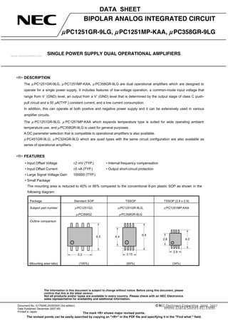
  • 1. The information in this document is subject to change without notice. Before using this document, please confirm that this is the latest version. Not all products and/or types are available in every country. Please check with an NEC Electronics sales representative for availability and additional information. SINGLE POWER SUPPLY DUAL OPERATIONAL AMPLIFIERS DATA SHEET Document No. G17929EJ3V0DS00 (3rd edition) Date Published December 2007 NS Printed in Japan 2006, 2007 The mark <R> shows major revised points. The revised points can be easily searched by copying an "<R>" in the PDF file and specifying it in the "Find what:" field. BIPOLAR ANALOG INTEGRATED CIRCUIT μPC1251GR-9LG, μPC1251MP-KAA, μPC358GR-9LG DESCRIPTION The μ PC1251GR-9LG, μ PC1251MP-KAA, μ PC358GR-9LG are dual operational amplifiers which are designed to operate for a single power supply. It includes features of low-voltage operation, a common-mode input voltage that range from V− (GND) level, an output from a V− (GND) level that is determined by the output stage of class C push- pull circuit and a 50 μA(TYP.) constant current, and a low current consumption. In addition, this can operate at both positive and negative power supply and it can be extensively used in various amplifier circuits. The μ PC1251GR-9LG, μ PC1251MP-KAA which expands temperature type is suited for wide operating ambient temperature use, and μPC358GR-9LG is used for general purposes. A DC parameter selection that is compatible to operational amplifiers is also available. μ PC451GR-9LG, μ PC324GR-9LG which are quad types with the same circuit configuration are also available as series of operational amplifiers. FEATURES • Input Offset Voltage ±2 mV (TYP.) • Internal frequency compensation • Input Offset Current ±5 nA (TYP.) • Output short-circuit protection • Large Signal Voltage Gain 100000 (TYP.) • Small Package The mounting area is reduced to 40% or 66% compared to the conventional 8-pin plastic SOP as shown in the following diagram. Package Standard SOP TSSOP TSSOP (2.8 x 2.9) Subject part number μ PC1251G2, μ PC358G2 μ PC1251GR-9LG, μ PC358GR-9LG μ PC1251MP-KAA Outline comparison 5.2 6.5 4.4 6.4 3.15 4.02.8 2.9 (Mounting area ratio) (100%) (60%) (34%) <R> <R> www.datasheet4u.com
  • 2. Data Sheet G17929EJ3V0DS2 μPC1251GR-9LG, μPC1251MP-KAA, μPC358GR-9LG ORDERING INFORMATION Part Number Selected Grade Package Package Type μ PC1251GR-9LG-E1-A Note Standard 8-pin plastic TSSOP (5.72 mm(225)) • 12 mm wide embossed taping • Pin 1 on draw-out side μ PC1251GR-9LG-E2-A Note Standard 8-pin plastic TSSOP (5.72 mm(225)) • 12 mm wide embossed taping • Pin 1 at take-up side μ PC1251GR(5)-9LG-E1-A Note DC parameter selection 8-pin plastic TSSOP (5.72 mm(225)) • 12 mm wide embossed taping • Pin 1 on draw-out side μ PC1251GR(5)-9LG-E2-A Note DC parameter selection 8-pin plastic TSSOP (5.72 mm(225)) • 12 mm wide embossed taping • Pin 1 at take-up side μ PC1251MP-KAA-E1-A Note Standard 8-pin plastic TSSOP (2.8 x 2.9) • 12 mm wide embossed taping • Pin 1 on draw-out side μ PC1251MP-KAA-E2-A Note Standard 8-pin plastic TSSOP (2.8 x 2.9) • 12 mm wide embossed taping • Pin 1 at take-up side μ PC1251MP(5)-KAA-E1-A Note DC parameter selection 8-pin plastic TSSOP (2.8 x 2.9) • 12 mm wide embossed taping • Pin 1 on draw-out side μ PC1251MP(5)-KAA-E2-A Note DC parameter selection 8-pin plastic TSSOP (2.8 x 2.9) • 12 mm wide embossed taping • Pin 1 at take-up side μ PC358GR-9LG-E1-A Note Standard 8-pin plastic TSSOP(5.72 mm(225)) • 12 mm wide embossed taping • Pin 1 on draw-out side μ PC358GR-9LG-E2-A Note Standard 8-pin plastic TSSOP(5.72 mm(225)) • 12 mm wide embossed taping • Pin 1 at take-up side μ PC358GR(5)-9LG-E1-A Note DC parameter selection 8-pin plastic TSSOP(5.72 mm(225)) • 12 mm wide embossed taping • Pin 1 on draw-out side μ PC358GR(5)-9LG-E2-A Note DC parameter selection 8-pin plastic TSSOP(5.72 mm(225)) • 12 mm wide embossed taping • Pin 1 at take-up side Note Pb-free (This product does not contain Pb in the external electrode and other parts.) <R> www.datasheet4u.com
  • 3. Data Sheet G17929EJ3V0DS 3 μPC1251GR-9LG, μPC1251MP-KAA, μPC358GR-9LG EQUIVALENT CIRCUIT (1/2 Circuit) PIN CONFIGURATION (Marking side) Q6 Q5 Q7 Q13 OUT V− V+ 6 A CC Q4 Q3Q2 Q1 Q8 Q9 Q12 Q11 Q10 IN II RSC 6 A 100 A 50 A μ μ μ μ + − OUT1 IN1 V− V+ OUT2 II2 IN2 1 2 3 4 8 7 6 5 II1 1 +− 2 −+ ABSOLUTE MAXIMUM RATINGS (TA = 25°C) Parameter Symbol μ PC1251GR-9LG, μ PC1251GR(5)-9LG μ PC1251MP-KAA, μ PC1251MP(5)-KAA μ PC358GR-9LG, μ PC358GR(5)-9LG Unit Voltage between V + and V − Note1 V + − V − −0.3 to +32 V Differential Input Voltage VID ±32 V Input Voltage Note2 VI V − − 0.3 to V − + 32 V Output applied Voltage Note3 VO V − − 0.3 to V + + 0.3 V Total Power Dissipation Note4 PT 440 mW Output Short Circuit Duration Note5 tS Indefinite s Operating Ambient Temperature TA −40 to +125 −40 to +85 °C Storage Temperature Tstg −55 to +150 −55 to +125 °C Note1. Note that reverse connections of the power supply may damage ICs. 2. The input voltage is allowed to input without damage or destruction independent of the magnitude of V + . Either input signal is not allowed to go negative by more than 0.3 V. In addition, the input voltage that operates normally as an operational amplifier is within the Common Mode Input Voltage range of an electrical characteristic. 3. A range where input voltage can be applied to an output pin externally with no deterioration or damage to the feature (characteristic). The input voltage can be applied regardless of the electric supply voltage. This specification which includes the transition state such as electric power ON/OFF must be kept. 4. This is the value of when the glass epoxy substrate (size: 100 mm x 100 mm, thickness: 1 mm, 15% of the substrate area where only one side is copper foiled is filling wired) is mounted. Note that restrictions will be made to the following conditions for each product, and the derating ratio depending on the operating ambient temperature. μPC1251GR-9LG: Derate at −5.5 mW/°C when TA > 69°C. (Junction − ambient thermal resistance Rth(J-A) = 183°C/W) μPC1251MP-KAA: Derate at −4.8 mW/°C when TA > 58°C. (Junction − ambient thermal resistance Rth(J-A) = 208°C/W) μPC358GR-9LG: Derate at −5.5 mW/°C when TA > 44°C. (Junction − ambient thermal resistance Rth(J-A) = 183°C/W) 5. Short circuits from the output to V + can cause destruction. Pay careful attention to the total power dissipation not to exceed the absolute maximum ratings, Note 4. <R> <R> www.datasheet4u.com
  • 4. Data Sheet G17929EJ3V0DS4 μPC1251GR-9LG, μPC1251MP-KAA, μPC358GR-9LG RECOMMENDED OPERATING CONDITIONS Parameter Symbol MIN. TYP. MAX. Unit Power Supply Voltage (Split) V ± ±1.5 ±15 V Power Supply Voltage (V − = GND) V + +3 +30 V ELECTRICAL CHARACTERISTICS μPC1251GR-9LG, μPC1251MP-KAA, μPC358GR-9LG (TA = 25°C, V+ = +5 V, V− = GND) Parameter Symbol Conditions MIN. TYP. MAX. Unit Input Offset Voltage VIO RS = 0 Ω ±2 ±7 mV Input Offset Current IIO ±5 ±50 nA Input Bias Current Note1 IB 14 250 nA Large Signal Voltage Gain AV RL ≥ 2 kΩ 25000 100000 Circuit Current Note2 ICC RL = ∞, IO = 0 A 0.7 1.2 mA Common Mode Rejection Ratio CMR 65 70 dB Supply Voltage Rejection Ratio SVR 65 100 dB Output Voltage Swing VO RL = 2 kΩ (Connect to GND) 0 V + − 1.5 V Common Mode lnput Voltage Range VICM 0 V + − 1.5 V Output Source Current IO SOURCE VIN (+) = +1 V, VIN (−) = 0 V 20 40 mA Output Sink Current IO SINK1 VIN (−) = +1 V, VIN (+) = 0 V 10 20 mA IO SINK2 VIN (−) = +1 V, VIN (+) = 0 V, VO = 200 mV 12 50 μA Channel Separation f = 1 to 20 kHz 120 dB μPC1251GR(5)-9LG, μPC1251MP(5)-KAA, μPC358GR(5)-9LG (TA = 25°C, V+ = +5 V, V− = GND) Parameter Symbol Conditions MIN. TYP. MAX. Unit Input Offset Voltage VIO RS = 0 Ω ±2 ±3 mV Input Offset Current IIO ±5 ±50 nA Input Bias Current Note1 IB 14 60 nA Large Signal Voltage Gain AV RL ≥ 2 kΩ 50000 100000 Circuit Current Note2 ICC RL = ∞, IO = 0 A 0.7 0.9 mA Common Mode Rejection Ratio CMR 65 70 dB Supply Voltage Rejection Ratio SVR 65 100 dB Output Voltage Swing VO RL = 2 kΩ (Connect to GND) 0 V + − 1.5 V Common Mode lnput Voltage Range VICM 0 V + − 1.4 V Output Source Current IO SOURCE VIN (+) = +1 V, VIN (−) = 0 V 30 40 mA Output Sink Current IO SINK1 VIN (−) = +1 V, VIN (+) = 0 V 15 20 mA IO SINK2 VIN (−) = +1 V, VIN (+) = 0 V, VO = 200 mV 30 50 70 μA Channel Separation f = 1 to 20 kHz 120 dB Notes1. The input bias current flows in the direction where the IC flows out because the first stage is configured with a PNP transistor. 2. This is a current that flows in the internal circuit. This current will flow irrespective of the channel used. <R>www.datasheet4u.com
  • 5. Data Sheet G17929EJ3V0DS 5 μPC1251GR-9LG, μPC1251MP-KAA, μPC358GR-9LG TYPICAL PERFORMANCE CHARACTERISTICS (TA = 25°C, TYP.) (Reference value) PT vs. TA ICC vs. V+ PT-TotalPowerDissipation-mW 600 500 400 300 200 100 0 0 20 40 60 80 100 120 140 μPC358G R-9LG μ PC 1251G R -9LG μPC1251M P-KAAWith 100 mm x 100 mm, thickness 1 mm glass epoxy substrate (refer to "ABSOLUTE MAXIMUM RATINGS Note 4" ) TA - Operating Ambient Temperature - °C ICC-SupplyCurrent-mA 0 0.5 1 1.5 2 0 10 20 30 40 RL = ∞ IO = 0 A TA = 25°C 125°C −40°C V+ - Power Supply Voltage - V (V− = GND) VIO vs. V+ VIO vs. TA VIO-InputOffsetVoltage-mV 0 10 20 30 40 3 2 1 0 -1 -2 -3 V+ - Power Supply Voltage - V (V− = GND) VIO-InputOffsetVoltage-mV -3 -2 -1 0 1 2 3 -50 0 50 100 150 V+ = +5 V, V− = GND each 5 samples data TA - Operating Ambient Temperature - °C IB vs. V+ IB vs. TA IB-InputBiasCurrent-nA 0 10 20 30 0 10 20 30 40 V+ - Power Supply Voltage - V (V− = GND) IB-InputBiasCurrent-nA 0 10 20 30 -50 0 50 100 150 V+ = +15 V V− = GND TA - Operating Ambient Temperature - °C <R> www.datasheet4u.com
  • 6. Data Sheet G17929EJ3V0DS6 μPC1251GR-9LG, μPC1251MP-KAA, μPC358GR-9LG IO SHORT vs. TA AV vs. V+IOSHORT-OutputShortCurrent-mA -20 0 20 40 60 80 30 40 50 60 70 − + IO SHORT TA - Operating Ambient Temperature - °C AV-VoltageGain-dB 160 0 40 120 80 40 0 302010 RL = 20 kΩ 2 kΩ V+ - Power Supply Voltage - V (V− = GND) AV, φ vs. f AV-VoltageGain-dB,φ-PhaseMargin-deg. 140 120 100 80 60 40 20 0 V = ±15 V± ±7.5 V ±2.5 V ±15 V ±7.5 V ±2.5 V AV φ f - Frequency - Hz VO vs. f CMR vs. f VO-OutputVoltageSignal-Vp-p 20 1 k 15 10 5 0 3 5 10 k 30 50 100 k 3005001 M − + +15 V VO VIN 100 kΩ 1 kΩ +7 V 2 kΩ f - Frequency - Hz CMR-CommonModeRejectionRatio-dB 120 100 1 k 1 M 100 80 60 40 20 10 k 100 k 0 f - Frequency - Hz 0.1 1 10 100 1 k 10 k 100 k 1 M www.datasheet4u.com
  • 7. Data Sheet G17929EJ3V0DS 7 μPC1251GR-9LG, μPC1251MP-KAA, μPC358GR-9LG PULSE RESPONSE SR - TA VIN-InputVoltage-VVO-OutputVoltage-V 4 0 3 2 1 0 3 2 1 20 40 60 80 RL ≥ 2 kΩ V = +15 V+ t - time - μs SR-SlewRate-V/μs -50 0 50 100 V = ±15 V± VO = ±10 V 0.4 0.3 0.2 0.1 0 SR− SR+ TA - Operating Ambient Temperature - °C VO vs. IO SINK ΔVO vs. IO SOURCE VO-OutputVoltage-V 0.01 0.1 1 10 0.01 0.1 1 10 100 V+ = +15 V V /2+ V+ VO IO SINK − + TA = −40°C 25°C 125°C IO SINK - Output Sink Current - mA ΔVO-OutputVoltagetoV+ -V 0 1 2 3 4 5 0.01 0.1 1 10 100 TA = −40°C 25°C 125°C V /2+ V+ ΔVO IO SOURCE + − IO SOURCE - Output Source Current - mA www.datasheet4u.com
  • 8. Data Sheet G17929EJ3V0DS8 μPC1251GR-9LG, μPC1251MP-KAA, μPC358GR-9LG PRECAUTIONS FOR USE O The process of unused circuits If there is an unused circuit, the following connection is recommended. Process example of unused circuits V+ V− V+ V− R R − + To potentials within the range of common-mode input voltage (VICM) Remark A midpoint potential of V+ and V− is applied to this example. O Ratings of input/output pin voltage When the voltage of input/output pin exceeds the absolute maximum rating, it may cause degradation of characteristics or damages, by a conduction of a parasitic diode within an IC. In addition, when the input pin may be lower than V− , or the output pin may exceed the power supply voltage, it is recommended to make a clump circuit by a diode whose forward voltage is low (e.g.: Schottky diode) for protection. O Range of common-mode input voltage When the supply voltage does not meet the condition of electrical characteristics, the range of common-mode input voltage is as follows. VICM (TYP.): V− to V+ − 1.5 (V) (TA = 25°C) During designing, temperature characteristics for use with allowance. O The maximum output voltage The range of the TYP. value of the maximum output voltage when the supply voltage does not meet the condition of electrical characteristics is as follows: VOm + (TYP.): V+ − 1.5 (V) (TA = 25°C), VOm − (TYP.) (IO SINK ≤ 50 μA): Approx. V− (V) (TA = 25°C) During designing, consider variations in characteristics and temperature characteristics for use with allowance. In addition, also note that the output voltage range (VOm + − VOm − ) becomes narrow when an output current increases. O Operation of output This IC consist an output level of a class C push-pull. Therefore, when a load resistance is connected to the midpoint potential of V+ , V− , a crossover distortion occurs at the transition state of output current flow direction (source, sink). O Handling of ICs When stress is added to ICs due to warpage or bending of a board, the characteristic fluctuates due to piezoelectric effect. Therefore, pay attention to warpage or bending of a board. <R> www.datasheet4u.com
  • 9. Data Sheet G17929EJ3V0DS 9 μPC1251GR-9LG, μPC1251MP-KAA, μPC358GR-9LG PACKAGE DRAWINGS (Unit: mm) Sy e Sxb M θ L c Lp D HE ZD A1 A2 A D1 E A3 S 0.145±0.055 (UNIT:mm) ITEM DIMENSIONS D D1 E HE A A1 A2 A3 3.15±0.15 3.00±0.10 4.40±0.10 6.40±0.20 1.20 MAX. 0.10±0.05 1.00±0.05 0.25 c θ e x y ZD 0.65 0.10 0.10 0.60 L Lp L1 0.50 0.60±0.15 1.00±0.20 P8GR-65-9LG 3°+5° −3° NOTE Each lead centerline is located within 0.10mm of its true position at maximum material condition. detail of lead end 8-PIN PLASTIC TSSOP (5.72mm (225)) 0.24b 4 5 1 8 L1 +0.06 −0.05 www.datasheet4u.com
  • 10. Data Sheet G17929EJ3V0DS10 μPC1251GR-9LG, μPC1251MP-KAA, μPC358GR-9LG 58 1 M S S S 8-PIN PLASTIC TSSOP(2.8x2.9) detail of lead end ITEM DIMENSIONS D D1 E e A1 A A2 L1 ZD c x y b 2.80 0.08 + + 1.03 MAX. 0.85 4.00 ± ±0.60 0.525 0.20 0.05 0.03 0.05 ±0.10 ± ± ± ± 0.05 0.145 0.10 0.10 0.22 0.05 Lp 0.37 A3 3° 5° 3° (UNIT:mm) P8MP-65-KAA D D1 L1 A A2 A1 ZD e b y Lp θ HE c A3 x 2.90 3.00 0.20 0.20 4 NEC Electronics Corporation 2006 S 0.65 0.25 HE E NOTE Each lead centerline is located within 0.10 mm of its true position at maximum material condition. <R> www.datasheet4u.com
  • 11. Data Sheet G17929EJ3V0DS 11 μPC1251GR-9LG, μPC1251MP-KAA, μPC358GR-9LG RECOMMENDED SOLDERING CONDITIONS The μ PC1251GR-9LG, μ PC1251MP-KAA, μ PC358GR-9LG should be soldered and mounted under the following recommended conditions. For soldering methods and conditions other than those recommended below, contact an NEC Electronics sales representative. For technical information, see the following website. Semiconductor Device Mount Manual (http://www.necel.com/pkg/en/mount/index.html) Type of Surface Mount Device μPC1251GR-9LG-A Note , μPC1251GR(5)-9LG-A Note , μPC358GR-9LG-A Note , μPC358GR(5)-9LG-A Note : 8-pin plastic TSSOP (5.72 mm (225)) μPC1251MP-KAA-A Note , μPC1251MP(5)-KAA-A Note : 8-pin plastic TSSOP (2.8 x 2.9) Process Conditions Symbol Infrared ray reflow Peak temperature: 260°C, Reflow time: 60 seconds or less (at 220°C or higher), Maximum number of reflow processes: 3 times. IR60-00-3 Wave soldering Solder temperature: 260°C or below, Flow time: 10 seconds or less, Maximum number of flow processes: 1 time, Pre-heating temperature: 120°C or below (Package surface temperature). WS60-00-1 Partial heating method Pin temperature: 350°C or below, Heat time: 3 seconds or less (Per each side of the device). P350 Note Pb-free (This product does not contain Pb in external electrode and other parts.) Caution Apply only one kind of soldering condition to a device, except for “partial heating method”, or the device will be damaged by heat stress. Remark Flux: Rosin flux with low chlorine (0.2 Wt% or below) recommended. REFERENCE DOCUMENTS Document Name Document No. QUALITY GRADES ON NEC SEMICONDUCTOR DEVICES C11531E SEMICONDUCTOR DEVICE MOUNT MANUAL http://www.necel.com/pkg/en/mount/index.html NEC SEMICONDUCTOR DEVICE RELIABILITY/QUALITY CONTROL SYSTEM-STANDARD LINEAR IC IEI-1212 REVIEW OF QUALITY AND RELIABILITY HANDBOOK C12769E NEC SEMICONDUCTOR DEVICE RELIBIALITY/QUALITY CONTROL SYSTEM C10983E <R> <R> www.datasheet4u.com
  • 12. μPC1251GR-9LG, μPC1251MP-KAA, μPC358GR-9LG The information in this document is current as of December, 2007. The information is subject to change without notice. For actual design-in, refer to the latest publications of NEC Electronics data sheets or data books, etc., for the most up-to-date specifications of NEC Electronics products. Not all products and/or types are available in every country. Please check with an NEC Electronics sales representative for availability and additional information. No part of this document may be copied or reproduced in any form or by any means without the prior written consent of NEC Electronics. NEC Electronics assumes no responsibility for any errors that may appear in this document. NEC Electronics does not assume any liability for infringement of patents, copyrights or other intellectual property rights of third parties by or arising from the use of NEC Electronics products listed in this document or any other liability arising from the use of such products. No license, express, implied or otherwise, is granted under any patents, copyrights or other intellectual property rights of NEC Electronics or others. Descriptions of circuits, software and other related information in this document are provided for illustrative purposes in semiconductor product operation and application examples. The incorporation of these circuits, software and information in the design of a customer's equipment shall be done under the full responsibility of the customer. NEC Electronics assumes no responsibility for any losses incurred by customers or third parties arising from the use of these circuits, software and information. While NEC Electronics endeavors to enhance the quality, reliability and safety of NEC Electronics products, customers agree and acknowledge that the possibility of defects thereof cannot be eliminated entirely. To minimize risks of damage to property or injury (including death) to persons arising from defects in NEC Electronics products, customers must incorporate sufficient safety measures in their design, such as redundancy, fire-containment and anti-failure features. NEC Electronics products are classified into the following three quality grades: "Standard", "Special" and "Specific". The "Specific" quality grade applies only to NEC Electronics products developed based on a customer- designated "quality assurance program" for a specific application. The recommended applications of an NEC Electronics product depend on its quality grade, as indicated below. Customers must check the quality grade of each NEC Electronics product before using it in a particular application. The quality grade of NEC Electronics products is "Standard" unless otherwise expressly specified in NEC Electronics data sheets or data books, etc. If customers wish to use NEC Electronics products in applications not intended by NEC Electronics, they must contact an NEC Electronics sales representative in advance to determine NEC Electronics' willingness to support a given application. (Note) • • • • • • M8E 02. 11-1 (1) (2) "NEC Electronics" as used in this statement means NEC Electronics Corporation and also includes its majority-owned subsidiaries. "NEC Electronics products" means any product developed or manufactured by or for NEC Electronics (as defined above). Computers, office equipment, communications equipment, test and measurement equipment, audio and visual equipment, home electronic appliances, machine tools, personal electronic equipment and industrial robots. Transportation equipment (automobiles, trains, ships, etc.), traffic control systems, anti-disaster systems, anti-crime systems, safety equipment and medical equipment (not specifically designed for life support). Aircraft, aerospace equipment, submersible repeaters, nuclear reactor control systems, life support systems and medical equipment for life support, etc. "Standard": "Special": "Specific": www.datasheet4u.com