IRJET- Selection & Design Procedure of Steering System of Formula Student (FS...
CPP_HPVC_2015_DESIGN_REPORT
1. 1
California State Polytechnic University, Pomona
2015 ASME HPVC Challenge
The Cal Poly Pomona Human Powered Vehicle Team
Presents
The Spirit of Randy
Team Officers
Jordan Jarnagin
Isaac Gower
Andrew Simpson
Team Members
Jonathan Tam
Melanie Bailey
Edward Huang
Randy Ballat
Cindy Lin
Thomas Gross
Wendy Chen
Julie Keong
Calvin Iba
Bruno Haesbaert
Martin Cabal
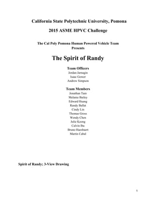
Spirit of Randy; 3-View Drawing
2. Abstrac
A
Competit
ct
Although it is
tions in the p
s true that Ca
past, there ha
al Poly Pom
as never bee
mona has com
en an ongoin
mpeted in Hu
ng organizati
uman Powere
ion set up at
ed Vehicle
the universi
2
ity to
3. 3
facilitate annual competition. During the 2014-2015 academic year, the current HPV team at Cal
Poly Pomona made it their primary goal to establish an organization made specifically to deal
with engineering human powered vehicles.
From initial conception to product completion of this year’s vehicle, CPP HPV has built
a team that has chartered an organization, acquired sponsors and shop space, dealt with insurance
and risk management issues, and then designed and fabricated a competition vehicle.
Our vehicle, the Spirit of Randy, is an un-faired front wheel drive recumbent that is
designed to be a practical and efficient vehicle for both competitive and everyday use.
Table of Contents
1. Design
1.1. Background
1.2. Objectives
1.3. Prior Work
1.4. Design Specifications
1.5. Concept Development and Evaluation of Alternatives
4. 4
1.5.1. Alternative Steering Mechanisms
1.6. Innovation:
1.7. Final Design
1.7.1. Ergonomics
1.7.2. Frame
1.7.3. Drivetrain
2. Analysis
2.1. Roll Protection System
2.2. Material Selection
2.3. Vehicle Dynamics
2.4. Cost Analysis
3. Safety
3.1. Design for Safety
3.2. Landing Gear
3.3. Safety Harness
3.4. Safety Accessories
3.5. Safety in Manufacturing
4. Conclusions
4.1. Evaluations
4.2. Recommendations
4.3. Conclusion
6. References
Appendix A
1. Design
1.1. Background
Mission Statement:
The CPP Human Powered Vehicle Team strives to create an environment that allows its
members to gain valuable experience in engineering design, project management, industry
relations, manufacturing, business, and performance testing.
1.2. Objectives
5. 5
Long Term Objective:
To design, fabricate, and compete with human powered vehicles collegiately on an annual basis.
2014-2015 Season Objective:
To set up the foundation of an organization with the purpose of annually competing in human
powered vehicle competitions by officially chartering, creating a diverse team of engineering
students, and building lasting relationships with the Cal Poly Pomona Department of Mechanical
Engineering and businesses that see the importance of investing in the education of tomorrow's
engineers.
Gantt Chart
Figure 1: 2015 Gantt Chart
1.3. Prior Work
Because this is the first year that Cal Poly Pomona has competed as an organization, there
is no prior work to draw from.
1.4. Design Specifications
The goals of our design this year were to build a vehicle conducive to the specifications
outlined in the 2015 HPVC rules. these are:
● 15 ft minimum vehicle turning radius
● Vehicle braking from 15 to 0 mph in less than 20 ft
6. 6
● Vehicle cargo area large enough to accommodate parcels of dimension 15x13x8 inches
● Rider safety harness
● Roll protection system that can support a 600 lbf topload with deflection of less than 2
inches
● Roll protection system that can support a 300 lbf side load with elastic deflection of less
than 1.5 inches
1.5. Concept Development and Evaluation of Alternatives
In the decision making process for what concept to base our vehicle off of, our team
came to five main possibilities: a bicycle with either front or rear wheel drive, a tadpole style
tricycle with rear wheel steering, or a delta style tricycle with either the front wheel driven or the
back wheels driven. As a first year team considering the lack of experience of its members, it
was decided to seek out a design that was feasible for the teams skill level. The team
implemented a decision matrix to come to this result (Figure 2).
The front wheel drive bicycle was chosen as the concept to model mainly due to its
having the most similarities to a standard bicycle in terms of mechanics. Our team viewed its
concept as a standard bicycle that was essentially cut in half and reversed so that the rear drive
mechanism could be placed in the front of the bike, while the undriven front wheel was moved to
the rear. A second main concern was building a two wheeled vehicle that could not be ridden.
Consulting an article featured in the book Bicycle Science called The Stability of the Bicycle, it
was concluded that not only would the design be a reasonably familiar concept to the team, but
also, from the article on stability, that while it is possible to construct bicycles that are more
difficult to ride than others, building a bicycle that is unrideable is very difficult, even for
someone with that as their design intent.
Tricycle
Bicycle Delta Tadpole
Category
Rear
Wheel
Drive
Front
Wheel
Drive
Rear Wheel
Drive
Front Wheel
Drive
Rear Wheel
Drive
Time
Allotment
Design 3 1 2 3 4
Fabrication 2 2 3 3 3
Design/
Fabrication
Stability 3 3 2 2 2
Drivetrain 3 1 3 4 4
Ergonomics 2 2 3 3 3
7. 7
Frame 2 2 3 3 4
Steering 3 4 2 4 3
Total 18 15 18 22 23
Figure 2: Decision Matrix
1.6. Innovation
Although the Spirit of Randy was designed primarily as a competition vehicle,
recreational use was considered in the ergonomic setup. Often with racing bicycles, designers
sacrifice rider comfort for efficiency. What makes our design innovative is its capacity to
accommodate both race and recreation situations. The seat position of the vehicle was decided
not only by evaluating efficiency parameters such as speed and visibility, but also taking into
account ergonomics and ability to be used by different riders. The steering system of the vehicle
allows for unique steering maneuvers such as steering with your feet or pulling on the handlebars
in a rowing motion to add power to the pedal stroke. Our goal in design was to create a vehicle
that could be used to compete in racing, but was also able to provide a comfortable and enjoyable
riding experience for recreational users of various ages.
1.7. Final Design
Our final design is an unfaired front wheel drive recumbent bicycle with a moving
bottom bracket (drivetrain turns with handlebars). As mentioned before, the drivetrain setup is
essentially that of a conventional bicycle, but with modified orientation and cable routing. The
roll protection system completely surrounds our tallest rider to prevent injury in the case of a
crash.
1.7.1 Ergonomics
Because the rider of the vehicle is such an important component in human powered
applications, it is necessary to incorporate ergonomics analysis into the design in order to create
a system that optimizes the power output of the rider while simultaneously offering a
comfortable riding experience.
8. 8
In order to accomplish this task, an ergometer was constructed in order to test various
rider speeds, positions, and experiences (Figure3). pictured below is the solid model of the
ergometer and the actual ergometer. Initially, during the design of the ergometer 5 axis of
freedom were deemed necessary to provide adequate adjustment for testing. Once built it became
aware that a design change would need to be made. To allow for finer height adjustment a scissor
lift was thought up and fabricated.
Figure 3 : Left: Solid model of ergometer, Right: Fabricated ergometer
Potential rider measurements were taken prior to designing the ergometer to get an idea
of required dimensions for seat distance from pedals and handlebars from seat back (Figure 4).
Shoulder width was also another important measurement not for the ergometer but for design of
the rollover protection system.
Height
(in)
Weight
(lb)
Inseam
(in)
Arm
Length (in)
Torso
(in)
Shoulder
Width (in)
Knee to
Foot (in)
Male Rider 1 73.5 190 33.5 31 23.5 19 22
Male Rider 2 71 290 30 32 24 21 21
Male Rider 3 71.5 155 32 31 19.5 18 20
Male Rider 4 67 152 28.5 31 19 18.5 20
Male Rider 5 69 160 31 32 19 17 20.5
Male Rider 6 71 165 32 28.8 23.3 17.8 20.5
Female Rider 1 71.5 195 33 33 21.5 19 21
Female Rider 2 65 170 27 27 19 16 18
Female Rider 3 65 140 30 27 19 17 19
Female Rider 4 62 140 29 26 17 17 19.5
Figure 4 : Potential rider measurements
9. T
one and f
was mad
1.7.2. Fr
T
which piv
chosen fo
D
inspiratio
as oppose
is difficu
Vendetta
extended
but prove
addressed
To test for rid
five minutes
e for each ri
rame
The frame wa
vot about a p
or its feasibi
During the de
on (Figure 6)
ed to turning
ult due to the
a in near-full
d pedalling m
es disadvant
d in the Spir
der comfort t
s in each pos
ider and then
F
as designed t
point just in
lity.
esign proces
). This recum
g the front w
e riders legs o
ly reclined p
motion. This
ageous when
rit of Randy’
three differe
ition multipl
n combined t
Figure 5: Ride
to incorpora
front of the
s, the comm
mbents desig
wheel. This a
operating in
osition whic
rider config
n maneuvera
’s design.
ent rider conf
le times to te
to get an ove
e Time vs. Aver
ate two struct
rider’s seat.
mercially avai
gn relies on t
aspect is cruc
the plane of
ch maximize
guration is w
ability in tigh
figurations w
est for comf
erall average
rage Speed
tures (a fron
As previous
ilable Cruzb
turning the b
cial since tur
f the front w
es their pow
well suited for
ht spaces is
were used. R
fort and spee
e (Figure 5).
nt portion and
sly stated, th
bike Vendett
bike by leani
rning the fro
wheel. Riders
wer output du
r fast rides w
desired. Thi
Riders road f
ed. An averag
d a rear port
his design wa
a was used f
ing into the t
ont wheel sha
s operate the
ue to the fully
with wide tur
is issue was
9
for
ge
tion)
as
for
turns
arply
y
rns,
10. T
vehicle fe
gives a sh
by reduci
it makes
turning a
In
first year
reasonab
T
the comm
be though
(with the
back-mo
(the steer
which att
from 0.5
total calc
The final desi
features a ste
horter wheel
ing the lag a
the vehicle m
and the abilit
n designing t
r designing a
le to fabrica
The front tria
mon point be
ht of simply
e seat stays c
st side of ou
r tube) is a se
taches to a p
inch steel tu
culated weigh
ign was very
eeper 35 degr
lbase for the
associated wi
more roundl
ty to mount a
the frame th
a recumbent
ate and safe t
angle pivots a
etween the fr
as the rear t
hanged to a
ur front triang
egment f 1.3
pin connectio
ubing. The b
ht of the fron
Figure 6: C
(courtesy
y similar to t
ree seat back
e vehicle, ma
ith the dragg
ly suitable fo
and dismoun
e main conc
vehicle we w
to use.
about a stand
ront and rear
triangle of a
fork). To ac
gle is a 135m
375 inch out
on at the top
ottom brack
nt frame wa
Cruzbike Vende
y of cruzbike.c
the Vendetta
k to put the r
aking its stee
ging of the re
or the events
nt the vehicle
cerns were si
wanted to be
dard 1-⅛” th
r of the fram
conventiona
ccommodate
mm wide fat
ter diameter,
of the head
ket occupies
s 9.14 lbs.
etta V20
com)
a in terms of
rider in a mo
ering more re
ear wheel. W
s at competit
e quickly as
implicity and
e sure that w
hreadless, no
me. The front
al bike transp
the cassette
t bike fork. T
, 0.028 inch
tube. A fron
the front mo
f operation, h
ore upright p
esponsive th
While this red
tion which re
well as recr
d strength. S
what was desi
on tapered he
t triangle of o
posed about
e on our fron
The top side
thick, 4130
nt chainstay
ost corner of
however our
position. Thi
han the Vend
duces top sp
equire tight
reational ridi
Since this is o
igned was
ead tube. Th
our vehicle c
t the seat stay
nt wheel, the
of the triang
steel tubing
is constructe
f the triangle
10
r
s
detta
peed,
ing.
our
his is
can
ys
gle
g
ed
e. The
11. T
roughly 4
tube and
relatively
clean we
welding.
heat affec
works an
of the rea
T
around 4
weight, a
bent to th
build a 3
figure 8)
The rear porti
43 feet of 1 i
dropouts the
y thin walled
ld joints. In
Care was ta
cted zones. T
nd welded di
ar frame is 1
The seat was
lbs when co
and strength.
he desired an
piece, wood
.
ion of the fra
inch outer di
e entirety of
d the initial p
the end the f
aken to ensur
The machine
rectly onto t
5 lbs.
made out of
ompleted. W
. Initially a 1
ngles. This s
den seat con
Figure 7: Fr
ame compris
iameter, 0.03
f the rear fram
plans were to
frame was m
re the joints
ed, 1018 stee
the ends of th
f 6061-T6 al
When designin
12”x33” rect
eat proved to
sisting of a h
ront Triangle A
ses the bulk
35 inch thick
me was mad
o tig weld th
mig welded d
were solid w
el dropouts w
he two rear-
uminum she
ng the seat t
tangle was cu
o be uncomf
headrest, bac
Assembly
of the vehic
k, 4130 steel
de in house. S
he frame whi
due to a lack
while minim
were purcha
most tubes.
eet of 0.10 in
the main con
ut from the a
fortable and
ckrest, and s
cle’s weight.
l tubing. Asi
Since the tub
ich would ha
k of experien
mizing excess
ased from Pa
The total ca
nch thicknes
ncerns were
aluminum sh
ultimately w
seat bottom (
It consists o
ide from the
bes were
ave produce
nce with tig
sive creation
aragon machi
alculated wei
ss weighing i
slimplicity,
heet stock an
we decided t
(as shown in
11
of
head
n of
ine
ight
in
nd
to
n
12. 12
Figure 8: Left: Seat Dimensions, Right: Aluminum Seat
1.7.3. Drivetrain
The drivetrain of the Spirit of Randy utilized a traditional road bicycle setup, but in a
modified orientation. because of the standard setup, it was unnecessary to custom design or
fabricate parts. The components used (Listed in Appendix A), are all in a standard road bicycle
configuration except for the cable routing throughout the vehicle. due to the change in frame
geometry from a traditional road bicycle, the routing of the cables for braking and gear shifting
had to be placed in a way that allowed full functionality while not inhibiting rider experience or
performance. because the Spirit of Randy is a moving bottom bracket type vehicle, the
possibility of a rider hitting a brake or shifting cable with their legs while riding can cause
unwanted braking or shifting and therefore is a major concern when determining a proper cable
routing scheme. The Spirit of Randy’s cable routing is as minimalist as possible in order to avoid
unwanted rider cable contact.
When choosing components for the Spirit of Randy’s drivetrain, the following was
considered.
FSA Gossamer cranksets offer good strength for a relatively low price. The chainrings
are 50/34t, also known as a compact crankset. This allows a wider gear range needed to
accelerate a heavy recumbent bicycle and still have high enough gears for higher speeds. Its
24mm axle fits the threaded bottom bracket that is specified. The Driven 11-28t cassette has
durable steel cogs riveted to an aluminum spider to reduce rotating weight. This gear
combination allows a wider gear range needed to accelerate a heavy recumbent bicycle and still
have high enough gears for higher speeds. Connecting the two is a KMC X10.93 chain. It is 10
speed compatible, and shifts well due to the shaping and champers on each link. The crankset
spins on a standard BSA threaded bottom bracket because of the ease of maintenance and
13. 13
availability. It measures 68mm wide to fit standard road cranksets, and has a 1.370”-24 thread
with the right side being left hand thread.
Shimano’s Tiagra rear derailleur is 10 speed compatible and can shift up to a 30t cog on
the cassette. The cage is also long enough to accept the wide tooth difference from the front
chainrings. The Shimano 105 band clamp front derailleur because is easy to mount to a round
tube and doesn’t require any complex hardware. Shimano 105 components are cost effective and
reliable. Shimano 105 brake and shifter hoods control the brakes and shifting. Although the left
shifter is made for 11 speed drivetrains, it will work with 10 speed front derailleurs because the
pull ratio is the same. They have indexing for easy and reliable gear changes, and also has trims
for the front derailleur. Connecting the shifters to the derailleurs is shimano SP41 4mm shifter
housing and cables. These are standard bike cables that are very smooth and dependable with
little friction. The inner cables are stainless steel to prevent corrosion
Tektro dual pivot brakes were chosen because they offer more power than conventional
single pivot brakes. The extra power will help decelerate the heavier recumbent bike in a
controlled and acceptable manner. M-system 5mm brake housing connects the brakes to the
hoods.
Since the Moonlander fat bike fork by Surly uses a 1 ⅛” non-tapered steerer tube, a 1 ⅛”
headset must be used. The DK headset has sealed cartridge bearings making it easy to assemble
and very reliable.
The first priority for the wheelset is strength. This bike will weigh more than typical
bikes and will have to withstand uneven surfaces in the endurance competition. Typical strong
wheelsets have 32 spokes with a three cross lacing. Mavic rims laced with straight gauge spokes
in a three cross pattern offer tons of strength. Shimano hubs are very reliable and roll on
rebuildable cup and cone bearings. Bontrager T1 25c tires have an all weather tread pattern and
the slightly larger volume absorbs more road imperfections than skinnier tires.
Recumbent bikes don’t need drop bars because there is no advantage in changing hand
positions. Pursuit handlebars offer good ergonomics, accept road brake and shifter levers, and are
available at bicycle retailers.
2. Analysis
2.1. Roll Protection System
14. 14
The roll protection system was designed to protect the rider in the event of a crash,
ensuring that the rider would not contact the ground if the vehicle were to completely roll-over.
The design parameters were those stated in section 1.4 (Design Specifications) and are
reproduced here.
● Roll protection system that can support a 600 lbf topload with deflection of less than 2
inches
● Roll protection system that can support a 300 lbf side load with elastic deflection of less
than 1.5 inches
Figure 9: FEA of the frame with a static 1440 lbf load oriented at the top of the roll protection system oriented at a
12 degree angle. Stress is shown on the left and deflection is shown on the right.
Theoretical stress analysis was performed using SolidWorks Finite Element Analysis
(FEA) tools. Solidworks allowed the team to quickly and easily analyze the frame under multiple
production situations by applying custom weldment profiles that reflected commercially
available tubeing. The roll protection system joins to the frame in many locations and essentially
is one with the frame. The selection of the fixed geometry to be used during the stress analysis
was based on the ASME HPVC west challenge criteria as well as how the frame would be tested
in real life. The rear drop-outs and the bottom of the front part of the RPS were constrained
During the FEA analysis, as seen by the green arrows in figures 9 and 10. The material studied
was AISI 4130 normalized which was the selected frame material. A design factor of 2.4 was
applied and so a 1440 ldf (~6.4 kN) load was applied to the top of the roll protection system at an
angle of 12 degrees with respect to the vertical. A 300 lbf load was also distributed across the
seat rails in order to simulate the pressure induced by the operator during operation. Under this
static condition, with the effects of gravity considered, the maximum induced stress was found to
be along the rear vertical rails concentrating at the drop-outs with a magnitude of approximately
15. 15
150 MPa and the maximum deflection was found to be at the top of the roll protection system
with a magnitude of approximately 0.79 mm
(~ 0.031 inches) as seen in Figure 9.
Figure 10: FEA of the frame with a static 600 lbf load oriented at the side of the roll protection system. Stress is
shown on the right and deflection is shown on the left.
A 300 ldf (~1335N) side load was applied to the two member joint of the roll protection system,
which is approximately shoulder high of the operator, as seen above in figure 10. Again taking
into account the effects of the riders distributed load (300lbf) and the effects of gravity, the
maximum induced stress was found in the midsection of the frame with a magnitude of
approximately 330 MPa and the maximum deflection was found to be at the top of the roll
protection system with a magnitude of approximately 10 mm (~0.39 inches) as seen in Figure 10.
According to MatWeb, the tensile yield strength of AISI 4130 is 435 Mpa in which case
the stress produced from FEA is well within the safe range with a maximum theoretical factor of
safety with respect to yielding of 1.32. Throughout the FEA analysis the Spirit of Randy never
showed signs of plastic deformation and was determined to have a maximum factor of safety
with respect to allowable elastic deflection of 3.75.
Initial simulations showed that 1in. x 0.028in. tubing, the thinnest gauge tubing available
to the team, would satisfy the design criteria and keep the frame weight to a minimum. However,
due to issues with material availability this tubing was not used in production and the team
increased the wall thickness up to the next available size of 0.035in. The frame passed the initial
design criteria and was cleared for fabrication
2.2. Material Selection
Material selection for the frame was based off the current popular bike frame materials
such as alloy steel and aluminum. With a small budget in mind and a skillset as mentioned
16. 16
before, an affordable yet competitive material was sought after. The two materials selected for
researched and comparison were 6061 aluminum due to its weight and 4130 steel due to its
strength. Aluminum, which has a density approximately a third of that of the steel was initially
chosen for its lighter characteristics. However, after conducting both cost and fabrication
analysis, AISI 4130 was chosen for its known weldability and (how much less than aluminum?)
reduced cost of nearly ___ that of aluminum.
4130 Steel, commonly referred to as Chromoly, is one of the lightest steels capable of
supporting a considerable amount of weight and is commonly used to manufacture bike frames.
It can also withstand a significant beating without damaging it’s integrity. The pros for picking
steel 4130 are its flexibility, durability, and cost efficiency.
4130 Steel has more give than aluminum and can handle stress up to 63,000 psi, which is
higher than that of aluminum, which is 31,000 psi. In addition, steel 4130 is cheaper than
aluminum. However, the primary con of 4130 steel is its weight. To combat this, thinner gauged
tubing was used which cut down weight while still maintaining the integrity of the bike's
structure.
2.3. Cost Analysis
The following cost analysis compares the cost of the Spirit of Randy as a prototype, the
cost to produce ten vehicles in one month, and the production cost to produce ten per month for
three years.
Category
Spirit of Randy as
presented
Monthly Production
Run (10 per month)
Three Year
Production Run
Capital Investment $0.00 $3,800.00 $136,800.00
Tooling $35.00 $35.00 $1,260.00
Parts and
Materials $1,662.64 $14,153.83 $509,537.88
Labor $0.00 $2,000.00 $72,000.00
Overhead $0.00 $1,728.47 $62,224.92
Total $1,697.64 $21,717.30 $781,822.80
Figure 11: Cost Analysis Summary
The above cost summary includes only the costs associated with the construction of the
vehicle, with expenses such as travel are not reflected in the analysis. For the Spirit of Randy as
presented, costs including capital investment, labor and overhead are noted as $0.00 due to the
17. 17
fact that no students were paid to work on the project and that the Cal Poly Pomona Department
of engineering provided the project with rent free space to work in. For more detailed cost
analysis refer to appendix A.
3. Safety
3.1. Design for Safety
The Spirit of Randy incorporates a roll protection system, 4-point harness, reflectors,
Brakes, and a padded seat (for long rides).
3.2. Safety Harness
The Spec D Tuning JDM Style four point universal racing harness seat belt was selected
as the vehicles primary and only safety harness. Weighing in around three and a half pounds this
harness will minimize the overall weight of the vehicle. The Spec D Tuning harness features 2
in. nylon webbing straps with 80 inches of arm strap, a quick release buckle and extra wide pads
located at the waist. The four point seat belt design applies pressure to the riders chest and waist
securely harnessing them to the seat. When applied correctly the Spec D Tuning harness will
keep the rider's torso secure and in place allowing their legs and arms to move freely. In the
event that the rider should put the vehicle through a complete roll-over, the Spec D Tuning
harness will keep the rider safely inside the vehicle. This component couples nicely with the
Spirit of Randy’s roll protection system. The 2 in. width of the strap allows more tension to be
produced and adds to the durability of the strap increasing its lifetime. The quick release buckle
makes entry and exit quick and simple for riders of various discipline and age. The extra wider
pads increase rider comfort by distributing the pressure across a larger area of the riders body.
These reasons make the selected harness a safe and long lasting component of the vehicle.
3.3. Safety Accessories
The Spirit of Randy is equipped with front lights, rear lights, and reflective stickers to
increase visibility during all hours of operation. The rider will not be encased in a vehicle shell
and therefore standard hand turn signals are to be used in the event of traffic maneuvers.
3.4. Safety in Manufacturing
Safety was a top priority during the manufacturing process of the ergometer, the frame
jig, the frame, and during vehicle assembly. The two shops used both required their own separate
safety certifications that were completed by each individual team member. While working in the
shop the team wore safety glasses, noted proper emergency procedures and filed the MSDS
18. 18
paperwork for all chemical products used. The members notching the frame tubes also used both
ear muffs and ear plugs to prevent damage to their hearing.
4. Conclusions
4.1. Evaluations
In its first organized competition effort, the 2015 Cal Poly Pomona Human Powered
Vehicle Team developed and constructed a vehicle that meets safety criteria and that offers a
unique rider experience. The Spirit of Randy was designed to achieve the team’s objective of
competing in the HPVC, and while the vehicle’s fabrication is not yet fully complete, the team is
confident that there is adequate time to finish manufacturing, complete the frame and component
testing and assemble the vehicle prior to the competition date.
4.2. Recommendations
While the Cal Poly Pomona Human Powered Vehicle Team will strive towards
improvement in design and manufacture in the coming years, the focus of this year was kept
simple to encourage feasibility in practice. While the practice of feasibility driven design kept
our team from being overly ambitious, in future design competitions the establishment of HPV
as an organization at Cal Poly Pomona will undoubtedly lead the team to pursue more complex
designs due both to having a running start with shop space and sponsors, and to having a
reasonably sized team at the beginning of the project.
The Cal Poly Pomona Human Powered Vehicle Team dedicated its effort for countless
hours of time this year to accomplish its main goal of organizing a lasting program. Having a
solid foundation is essential for any project that is reoccurring. After experiencing the lengthy,
up and down process of chartering an organization this year, the team still recommends
chartering as a means to not only obtain a fuller experience of what real world project
development is like in terms of management, documentation, money handling and external
relations, but to also establish the opportunity for future engineering students to take advantage
of what has been done and improve on it rather than starting from absolutely nothing every year
and working hard to accomplish things that have little to do with design and fabrication.
4.3. Conclusion
At this point in the Spirit of Randy’s development, the team has been successful in
achieving its main goal of building an organization, and is well on its way to competition. As the
design process progresses, the team continues to learn new things in various areas such as design
practice, manufacturing, business relations, and most importantly, slack and lead times. As the
competition approaches team is confident it will perform well at its first competition.
19. 19
5. References
Wilson, David Gordon, Jim Papadopoulos, and Frank Rowland. Whitt. Bicycling Science.
Cambridge, MA: MIT, 2004. Print.
"MatWeb - The Online Materials Information Resource." MatWeb - The Online Materials
Information Resource. N.p., n.d. Web. 01 Apr. 2015.
Appendix A: Cost Analysis
The following is cost information for the production of one Spirit of Randy vehicle.
Capital Investment
TIg Welder $1,000.00
Tube Notcher $2,500.00
Cut-Off saw $200.00
Assorted Small Tools $100.00
total $3,800.00
tooling
angle grinder $15.00
hole saws $20.00
Total $35.00
21. 21
4130 steel tubing (1-3/8x.035) $29.33
4130 steel sheet (.1 thick) $12.33
Wood for Ergometer/jig $3.00
Total $274.73
Labor Per Month
Per Hour $25
Hours per week 40
Number of workers 2
total $2,000
Overhead
Facility Per Month 1000 Sq ft. area
Rent $600.00
Utilities $1,000.00
Website Maintenance $25.00
New Tools/Repair $50.00
Consumables Per Month
Welding Filler Rod $20.00
Hole Saws $23.47
Spray Adhesive $10.00
Total $1,728.47