Recommended

Recommended
More Related Content
What's hot
What's hot (20)
Similar to Precision structure build and analysis
Similar to Precision structure build and analysis (20)
Recently uploaded
Recently uploaded (20)
Precision structure build and analysis
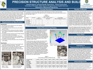
- 1. PRECISION STRUCTURE ANALYSIS AND BUILD Gabriela Alatorre, Leonardo Bonilla, Garret Dunn, Johann Franco-Ortiz University of Rochester, Hajim School of Engineering and Applied Sciences Department of Mechanical Engineering Problem Statement The build and analysis of a simple truss structure was required in order to obtain information on locked-in strain of a simple truss structure made of acrylic members. In order to calculate the locked-in strain, masses were loaded and unloaded in various patterns while measuring the strain when the structure was upright and flipped 180 degrees. Data was collected in order to calculate the locked-in strain by subtracting the downward strain from the upward strain. Requirements and Specifications Requirements: ● The structure must be made out of low cost materials. ● Strain gauges must be utilized. ● The masses must mount to the structure with at least 3 points of contact. ● The structure must be modular and be able to support at least 3 different configurations of loading and unloading the masses. ● The structure and test procedure must be made/ executed such that the process can be repeated. ● The structure must be able to be rotated 180 degrees, while maintaining the same boundary conditions, in order to average out the strain readings. ● The structure must have some way to lock in the strain due to the masses. Specifications: ● The material used for the structure must be rigid but still easily deformed (Modulus between 1-200 GPa). ● Deformations must stay within linear region of material but be large enough to get significant results with strain gauges. Strain Levels must be at least in the microstrain regime for strain gauge to read results. A rectangular truss structure design was chosen mostly because of its ability to meet the desired requirements, its simple design that helped with ease of manufacturing, and several others reasons shown in the Pugh Matrix (Table 1). Results/ Challenges Evaluation of Requirements and Specifications The current design has satisfied the established requirements and specifications. Acrylic was selected as the construction material due its low modulus (2 GPa). Acrylic also produced strain results within the microstrain regime. The support structure for the truss was constructed with a rotating bar in order to sustain 180 degree rotation. This allowed for the truss structure to maintain the same boundary conditions once it was rotated. 4 loading locations exceeded the requirement of 3 loading configurations. Spherical bearings between the masses and horizontal beams allowed for multiple points of contact even when the structure was rotated. Analysis/Manufacturing/Testing Concept Description Acknowledgements Future Work There has been a minimal amounts of research looking into locked-in strain. Future tests with various modifications could be done to investigate locked-in strain further, including; different shaped truss structures, structures made from different materials, use of more than three masses during testing, and different methodologies to replicate the locked-in strain. Design Strength* Ease of Manufacturing Ability to easily be mounted and rotated Customizability (Different loading pattern options) Triangular -1 +1 -1 -1 Rectangular - - - - Hexagonal -1 -1 -1 +1 Hexagonal(2) -1 -2 -1 +2 TABLE 1 PUGH MATRIX *In this case a less resilient structure is preferred. This project would not have been possible without the initial proposal and continued guidance of Leslie Johnson, the counsel of Professor Muir, and the advice of Scott Russell. The manufacturing portion of the project, which was pertinent to the project’s completion,was made possible by the ordering assistance of Tal Haring and the fabrication assistance of Jim Alkins and John Miller. Professor Ellis, Professor Genberg and Mike Pomerantz also provided initial advice on alternative strain measurement methods which was crucial in determining which method was used. Figure 2. Truss Structure Rotated 180 degrees Figure 1. Truss Structure Upright Locked-In Strain Gauge 1 Gauge 2 Gauge 3 Gauge 4 Gauge 5 Gauge 6 Gauge 7 Gauge 8 Loading One Weight 0.000192 -0.000382 0.000122 0.000386 -0.000113 -0.000432 -0.000009 -0.000066 Two Weight 0.000693 -0.000502 0.000593 0.000585 -0.000257 -0.000611 -0.000002 -0.000097 Three Weights 0.000747 -0.000555 0.000740 0.000675 -0.000377 -0.000707 0.000008 -0.000076 Unloading One Weight -0.065484 -0.060015 -0.063757 0.000384 0.000000 -0.000178 0.000056 0.000123 Two Weights -0.065484 -0.060015 -0.063758 0.000549 0.000000 -0.000406 0.000052 0.000089 Three Weights n/a n/a n/a n/a n/a n/a n/a n/a TABLE 3 CALCULATED LOCKED-IN STRAIN VALUES All eight strain gauges were wired into an eight channel data acquisition device. This device was plugged into a computer that was running a LABVIEW program. Using the program, 100 data points were taken three times for each test configuration. The structure was tested using 1-3 weights, in an up orientation and down, and in different loading sequences. The resulting data files were manipulated in MATLAB which outputted figures of the data as well as average values for the eight channels. These average values were taken and manipulated further in excel. In particular baselines were subtracted out from the data to help zero the channels. From there, the Up configurations were subtracted from the Down configurations for the Loading and Unloading patterns. The locked-in strain was the calculated in Table 3. Only minor changes occurred during testing. The ends of the vertical legs experienced some minor cracking which was easily remedied. One of the strain gauges also seemed to fail during testing as the data was inconsistent. This was unfortunate but not viewed as an issue since six gauges were required and the team placed eight. The structure which was fitted with eight uni-axial strain gauges was designed such that deflections when the structure was loaded were easily measured by the gauges. The structure was loaded with ~1 lb weights in different locations and loading patterns both upright and flipped 180 degrees down. By obtaining this strain data, gravity could be “averaged out” and a correlation between the FEA model and the physical model could hopefully be made which would help the aerospace industry better understand locked-in strain. The test structure, seen to the right, was made entirely out of acrylic. This material was chosen for its low modulus of elasticity and ease of manufacturing. Rod end bearings were used at the ends of all the vertical legs to make the forces in the legs be more axial and more easily read by the gauges. The two side support structures seen in Figures 1 and 2 had a main pivot pin and a clamping bar in order to rotate the structure. The clamping bar rotated on the main pivot pin and two locking pins were put into it at either end. The base plate would be inserted onto all three pins on both sides and clamps would be added to hold it from rotating. By clamping in the direction normal to gravity, no external forces would be added to the structure in the desired direction. Figure 1. Linear Buckling FEA Analysis Figure 1. Three masses loaded