
Recommended
More Related Content
What's hot
What's hot (20)
Viewers also liked
Similar to Final Image Evaluation - AP Ankle
Similar to Final Image Evaluation - AP Ankle (20)
Recently uploaded
Recently uploaded (20)
Final Image Evaluation - AP Ankle
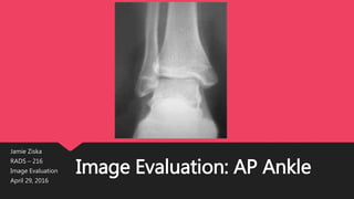
- 1. Image Evaluation: AP Ankle Jamie Ziska RADS – 216 Image Evaluation April 29, 2016
- 2. HIPAA Compliance This image is HIPAA compliant. It does not include any information that would violate patient confidentiality.
- 3. Marker & Patient ID The image does not have an anatomical side marker included. An anatomical side marker should be included in the image with technologist ID. An AP marker to indicate the position/projection could also be added. This marker does not superimpose any pertinent anatomy. Based on this marker placement, the image is displayed correctly. R 123
- 4. Radiation Hygiene Three sides of beam restriction should be seen in an image, including the side closest to the patient’s gonads. If the gonads are within 5 centimeters of the primary beam, secondary shielding should be used. This image does not show any evidence of any collimation or gonadal shielding. This image does not adhere to proper beam restriction/shielding rules. Red lines show proper collimation.
- 5. Completeness of Positions/Projections The AP position/projection is routine. Other positions/projections include: Mediolateral Lateral AP Internal Oblique AP External Oblique All pertinent anatomy is visualized in this image.
- 6. Artifact Identification This image does not include any of the following artifacts that would interfere with this study: 1. No physical artifacts 2. No patient clothing/belongings 3. No hospital paraphernalia 4. No superimposing body parts over the area of interest 5. No indwelling objects or foreign bodies 6. No excess fog or any CR/DR artifacts
- 7. Image Sharpness There is no gross voluntary motion visible in the image. The image shows no evidence of excessive quantum mottle. There is no evidence of a double or previous exposure. Grid lines, artifacts, or cut-off cannot be seen. Ankles are imaged table top and do not require a grid.
- 8. Image Sharpness Size distortion in this image does not appear to be greater than expected. There does not appear to be any shape distortion caused by CR/part/IR alignment.
- 9. Accurate Part Positioning The part is aligned correctly to the image media with the joint in the center of exposure area. The midpoint of the IR should be centered to the part midway between the medial and lateral malleoli.
- 10. Accurate Part Positioning The CR is centered to within 1 cm of the part, entering midway between the medial and lateral malleoli. The CR is adequately aligned, entering perpendicular to the joint space and to the IR. The CR’s alignment does conform to an acceptable exposure recognition field/template because it has no margins of collimation.
- 11. Accurate Part Positioning Place the patient in the supine or seated position with the affected limb fully extended. Adjust the ankle joint in the anatomic position (foot pointing straight up) to obtain a true AP projection. Flex the ankle and foot enough to place the long axis of the foot in the vertical position. Ball and Egbert stated that the appearance of the ankle mortise is not appreciably altered by moderate plantar flexion or dorsiflexion as long as the leg is rotated neither laterally nor medially. Shield gonads. Direct CR perpendicular through the ankle joint at a point midway between the malleoli.
- 12. Accurate Part Positioning The following should be clearly shown: Evidence of proper collimation Tibiotalar joint space Ankle joint centered to exposure area Normal overlapping of the tibiotalar articulation with the anterior tubercle slightly superimposed over the fibula Talus slightly overlapping the distal fibula No overlapping of the medial talomalleolar articulation Medial and lateral malleoli Talus with proper density Soft tissue
- 13. Accurate Part Positioning Based on the positioning and evaluation criteria, the part is correctly positioned.
- 14. Judicious Exposure Techmique The most radiolucent structures are the surrounding oft tissue and joint spaces. The most radiopaque structure is the bony cortex. Both are visible in this image. I believe the contrast (window width) and brightness (window level) are adequate for this image. I believe the EI value would be within normal range.
- 15. Accept or Reject? I believe this image meets minimal requirements and should be accepted. Corrections: Include marker with technologist ID Collimate so that 3 or more sides show adequate beam restriction
- 16. References Frank, Eugene D, Bruce W. Long, Barbara J. Smith, Vinita Merrill, and Philip W. Ballinger. Merrill's Atlas of Radiographic Positioning & Procedures. St. Louis, Mo: Mosby/Elsevier, 2007. Print. https://holyfamily9.blackboard.com/bbcswebdav/pid-577620-dt-content-rid- 1551345_1/courses/RADS-216-A-2016SP/Positioning_Criteria_16.pdf https://holyfamily9.blackboard.com/bbcswebdav/pid-577621-dt-content-rid- 1551339_1/courses/RADS-216-A-2016SP/Markers_Image_Display_16%281%29.pdf https://holyfamily9.blackboard.com/bbcswebdav/pid-576542-dt-content-rid- 1541230_1/courses/RADS-216-A-2016SP/Distortion_16.pdf https://holyfamily9.blackboard.com/bbcswebdav/pid-567096-dt-content-rid- 1493317_1/courses/RADS-216-A-2016SP/RADS-216-A- 2016SP_ImportedContent_20160111094521/Gen_Imag_Eval_Info_16.pdf http://www.dcorthoacademy.com/journal/journal_09/dec_09/diagnostic_imaging_dec09.php