Design and Drawing of Reinforced concrete structures
Example of Structural Beam Calculations
1. Project Made by Date Job No
Client Ian Lumby 16-3-16 7302
Checked Revision Page No
DB - 6.1
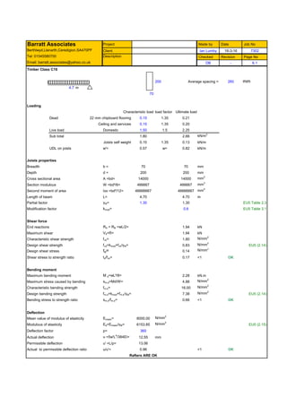
Timber Class C16
200 Average spacing = 260 mm
4.7 m
70
Loading
Characteristic load load factor Ultimate load
Dead 22 mm chipboard flooring 0.15 1.35 0.21
Ceiling and services 0.15 1.35 0.20
Live load Domestic 1.50 1.5 2.25
Sub total 1.80 2.66 kN/m2
Joists self weight 0.10 1.35 0.13 kN/m
UDL on joists w'= 0.57 w= 0.82 kN/m
Joists properties
Breadth b = 70 70 mm
Depth d = 200 200 mm
Cross sectional area A =bd= 14000 14000 mm2
Section modulous W =bd²/6= 466667 466667 mm3
Second moment of area Ixx =bd³/12= 46666667 46666667 mm4
Length of beam L= 4.70 4.70 m
Partial factor γM= 1.30 1.30 EU5 Table 2.3
Modification factor kmod= 0.6 EU5 Table 3.1
Shear force
End reactions RA = RB =wL/2= 1.94 kN
Maximum shear Vd=R= 1.94 kN
Characteristic shear strength fvk= 1.80 N/mm2
Design shear strength fvd=kmod×fvk/γM= 0.83 N/mm2
EU5 (2.14)
Design shear stress td= 0.14 N/mm2
Shear stress to strength ratio td/fvk= 0.17 <1 OK
Bending moment
Maximum bending moment M d=wL²/8= 2.28 kN.m
Maximum stress caused by bending sm,d=Md/W= 4.88 N/mm2
Characteristic bending strength fm,k= 16.00 N/mm2
Design bending strength fm,d=kmod×fm,k/γM= 7.38 N/mm2
EU5 (2.14)
Bending stress to strength ratio sm,d/fm,d= 0.66 <1 OK
Deflection
Mean value of modulus of elasticity Emean= 8000.00 N/mm2
Modulous of elasticity Ed=Emean/γM= 6153.85 N/mm2
EU5 (2.15)
Deflection factor p= 360
Actual deflection u =5w'L4
/384EI= 12.55 mm
Permissible deflection u' =L/p= 13.06
Actual to permissible deflection ratio u/u'= 0.96 <1 OK
Rafters ARE OK
Barratt Associates
Berthlwyd,Llanarth,Ceredigion.SA470PF
Tel: 01545580700 Description
Email: barratt.associates@yahoo.co.uk