Electromagnetic energy or RF energy will play a pivotal role in wireless technology and wireless communication in the impending future. The paper proposes a concept for a patch antenna based system that can harness RF energy upon triggering and can convert the harnessed RF to DC from the radio frequency of 1 GHz to 3 GHz, the design frequency is 2.4GHz. The patch antenna system contains a high gain patch antenna along with a wireless communicating module and a conversion circuit. The return loss of the antenna is approximately 27.1dB. The power gain is 30.1 dBm .The converter circuit is designed in), Multi-Sim to get an output voltage of around 5V that can be used to power a mobile-device or maybe stored in a battery. The triggering part is done with the help of a T-mote which is simulated in a network simulator, Cooja. The patch antenna is simulated in High Frequency Structural Simulator
Navigating Complexity: The Role of Trusted Partners and VIAS3D in Dassault Sy...
Designing an Antenna System That Can Perform Conditional RF to DC Harnessing To Generate Electricity
1. IOSR Journal of Electronics and Communication Engineering (IOSR-JECE)
e-ISSN: 2278-2834,p- ISSN: 2278-8735.Volume 12, Issue 1, Ver. III (Jan.-Feb. 2017), PP 18-22
www.iosrjournals.org
DOI: 10.9790/2834-1201031822 www.iosrjournals.org 18 | Page
Designing an Antenna System That Can Perform Conditional RF
to DC Harnessing To Generate Electricity
Raghunandan G. Kalibhat 1
, Arun L. Kakhandki 2
, Ramakrishna S.3
Dr.Priyatamkumar4
1
U.G. Student (Dept. of Electronics and Communication Engineering, B.V.Bhoomraddi College of Engineering
and Technology, Hubli ,India)
2
Associate Professor (Dept. of Electronics and Communication Engineering, B.V.Bhoomraddi College of
Engineering and Technology, Hubli ,India)
3
Assistant Professor (Dept. of Electronics and Communication Engineering, B.V.Bhoomraddi College of
Engineering and Technology, Hubli ,India)
4
Professor (Dept. of Electronics and Communication Engineering, B.V.Bhoomraddi College of Engineering and
Technology, Hubli ,India)
Abstract: Electromagnetic energy or RF energy will play a pivotal role in wireless technology and wireless
communication in the impending future. The paper proposes a concept for a patch antenna based system that
can harness RF energy upon triggering and can convert the harnessed RF to DC from the radio frequency of 1
GHz to 3 GHz, the design frequency is 2.4GHz. The patch antenna system contains a high gain patch antenna
along with a wireless communicating module and a conversion circuit. The return loss of the antenna is
approximately 27.1dB. The power gain is 30.1 dBm .The converter circuit is designed in), Multi-Sim to get an
output voltage of around 5V that can be used to power a mobile-device or maybe stored in a battery. The
triggering part is done with the help of a T-mote which is simulated in a network simulator, Cooja. The patch
antenna is simulated in High Frequency Structural Simulator.
Keywords: Cooja, HFSS (High Frequency Structural Simulator), Multi-Sim, Patch antenna
I. Introduction
The wireless technology has dominated its predecessor in many aspects like the ease of use, long range
accessibility. Also with the ever-growing developments it also made affordable for a common person. Wireless
technology uses radio waves to transmit information without cables or wiring. Wireless operations permit
services, such as long-range communications, that are impossible or impractical to implement with the use of
wires. Common methods of achieving wireless communications include the use of
other electromagnetic wireless technologies, such as light, magnetic, or electric fields or the use of sound. One
of the major and recent developments in the same is the use of wireless charging for mobile applications. Mobile
giant Samsung has come out with the concept of electricity and magnetism to develop a wireless charging
system. This system consists of an inductance pad. Placing the mobile phone on the pad will charge it
automatically. In electromagnetic theory, it is classified as a near-field activity. The charging pad so developed
makes use of the concept of mutual inductance to accomplish the same. A current flowing through the pad will
give rise to a magnetic flux. This magnetic flux is then linked to the mobile phone by mutual inductance. The
Lenz’s law comes into picture here. The mobile phone there-by tries to prevent the cause for this flux by
generating a current. This current is then controlled and used for charging the phone. Hence, the near-field
activity makes use of magnetism. On the contrary, far-field activity makes use of electromagnetic waves
especially the microwaves for its applications. These electromagnetic waves can be easily generated using an
oscillator or some other source and then be transmitted with the help of an antenna. At the receiving end, a
receiver antenna captures these waves and then passes it for the further processing. Since these waves carry both
electrical and magnetic energy, both or either of these can be extracted and used for different applications.
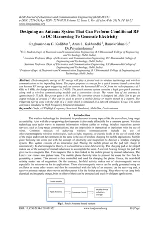
Fig 1. Patch Antenna based system
2. Designing an antenna system that can perform conditional RF to DC harnessing to generate ..
DOI: 10.9790/2834-1201031822 www.iosrjournals.org 19 | Page
II. Methodology
Fig 2. Flowchart
2.1 Antenna Modeling
The antenna modeled and simulated with the help of simulation software by Ansys. The antenna
designed is a patch antenna with the operation range of 1-3GHz. The desired frequency of operation of the patch
antenna simulated in High Frequency Structural Software is 2.4GHz. The substrate used for the patch antenna is
FR4 or Fire Resistant epoxy which has a very good mechanical strength also with an efficiency of 99.6%. It also
helps in size reduction. FR4 provides a relatively high bandwidth when compared to other materials used for
substrate like Roger-4350, Benzocyclobutane etc. The specification of the FR4 substrate used in this concept is
as shown in the table.
Table 1. Antenna material specification
Fig 3. Antenna modeling using HFSS
2.2 Circuit Simulation
The circuit simulation is done using the Multi-Sim software by National Instruments. The RF-DC
converter circuit is a Cockcroft-Walton multipier circuit. The peculiarity of this circuit is that it not only
converts the AC to DC, but also elevates the level of output obtained. Since the operation involves dealing with
the micro-waves traditional diodes cannot be used. Schottky diodes 10BQ015 along with diodes 1BH62 here act
as the rectifiers. The first part of the circuit elevates the AC level which is rectified by the second part of the
circuit. The RF wave received by the antenna is converted to voltage. Here, for the frequency of 2.4 GHz an
alternating voltage of 7.19 V is given as input to the converter circuit. The first part of the circuit elevates it to
9.617V which is later brought down 5.4V.
Table 2. Descripton of circuit components
Description Notation Ratings
Capacitors C1,C2,C3,C4,C5 1nF, 10V
Diodes(Fast-recovery) D6,D7,D8,D9 100V, 1A
Schottky diodes D2,D3,D4,D5 3 GHz
Resistors R2,R3,R4 1K ohm and 2.5K ohm
Description Value
Material Used FR4 epoxy
Frequency of operation 2.4 GHz
Width 38.03 mm
Height 29.46 mm
Dielectric Constant 4.4
3. Designing an antenna system that can perform conditional RF to DC harnessing to generate ..
DOI: 10.9790/2834-1201031822 www.iosrjournals.org 20 | Page
Fig 4. Cockroft-Walton circuit simulation using Multi-Sim
2.3 Contiki Module
The contiki module is used for the purpose of communication between the transmitter and receiver
systems. Contiki 2.7 OS is used here.The module consists of a T-mote. The T-mote is simulated in the Cooja
network simulator and the results obtained are shown in the figure. Communication between the two motes is
simulated under two conditions once when they are in range and when they are out of range and is shown below.
Fig 5. Mote simulation in Cooja
III. Procedure
The design of patch antenna was done on a substrate with the dimensions 38mm X 29mm. The antenna
is a high gain antenna with a frequency of operation from 1-3GHz. The power gain curve shows that the antenna
has a gain of 30.15 dBm. This is equivalent to an rms voltage of 7.19V, 2.4GHz. This is given as the input to the
Cockcroft-Walton circuit. The circuit in turn provides an output to 9.6V that is brought down to 5.4V. Now, the
working of the system is as follows. Consider a transmitter and receiver along with their corresponding circuits
respectively. The transmitter circuit can be an oscillator that can generate desired frequencies. The research
makes an important assumption of the Contiki-communicating module being present in the transmitter antenna
as well as the receptor antenna. To begin with whenever there is a need for charges/ energy for an end device
say mobile-phone, it sends a request to the receptor Contiki T-mote. This module in turn sends a request to the
transmitter Contiki T-mote. It allows for the transmission of the microwave signals generated by the oscillator.
An actuator can be used at the receptor antenna to allow it to capture the microwave signals. The transmitting
antenna must be aimed properly to receive more power. The received power is then harnessed in to DC for
powering the load.
Table 3. Abbrevations and Acronyms
DC Direct Current
RF Radio Frequency
HFSS High Frequency Structural Software
Unit
dBm - power gain of antenna
GHz – frequency
IV. Results
The working frequency of the antenna is as shown in the figure along with its power gain. Return loss
can be imagined as the ratio of power incident on the antenna to the power lost as a result of lossy nature (due to
different types of antenna apertures that play role in heating the antenna, dissipating the power).The graph of
return loss in dB vs frequency is plotted and is shown.
4. Designing an antenna system that can perform conditional RF to DC harnessing to generate ..
DOI: 10.9790/2834-1201031822 www.iosrjournals.org 21 | Page
Fig 6. Return loss of the patch antenna
The graph shows that the antenna has a return loss of 27.1dB at the designed frequency of 2.4GHz. The power-
gain graph shown depicts a maximum power of 30.15dBm. Power gain is the graph of peak gain in dBm vs
theta.
Fig 7. Power gain of the antenna
As explained earlier the converter circuit has two stages. The first stage elevates the signal. The second stage
rectifies it. The output is shown at the end of the first stage and then the second stage respectively.
Fig 8. Output of the cockroft-walton converter circuit
Since the transmission of the microwave signals can be only triggered upon the interception of
messages by the Contiki T-mote, placing of the T-motes also plays an important role as they communicate over
the radio. The following snippets show how the efficiency varies with the distance. In the first snippet the motes
are in range and the distance is around 10m. In the second snippet the motes are out of range and the distance is
around 30m.
5. Designing an antenna system that can perform conditional RF to DC harnessing to generate ..
DOI: 10.9790/2834-1201031822 www.iosrjournals.org 22 | Page
Fig 9. Results when the motes are in range and out of range
V. Conclusion
The present research makes use of a substrate of dimensions 38mm X 29 mm. This dimension can be
reduced or be more optimised to make the system more portable. Further the communication between the
transmitter and receiver system can be made more efficient by using alternative mechanisms. This in turn may
increase the working distance enhancing the efficincy of reception also.More focus can be levied on
communication between the motes and the load in case if the system is purely used for charging application to
achieve complete automation.
References
[1]. Balanis, Constantine A. Antenna theory: analysis and design. John Wiley & Sons, 2016.
[2]. Fatthi Alsager, Ahmed. "Design and Analysis of Microstrip Patch Antenna Arrays." (2011).
[3]. Prasad, K. D., and Deepak Handa. Antenna and wave propagation. Satya Prakashan, 2003.
[4]. Kraus, John D., and Ronald J. Marhefka. "Antenna for all applications." Upper Saddle River, NJ: McGraw Hill (2002).
[5]. Reddy, M. Venkateswara, K. Sai Hemanth, and CH Venkat Mohan. "Microwave Power Transmission–A Next Generation Power
Transmission System." IOSR Journal of Electrical and Electronics Engineering (IOSRJEEE), e-ISSN (2013): 2278-1676.
[6]. Gabrillo, L. J., M. G. Galesand, and J. A. Hora. "Enhanced RF to DC converter with LC resonant circuit." IOP Conference Series:
Materials Science and Engineering. Vol. 79. No. 1. IOP Publishing, 2015.
[7]. Mane, Mrs Punita, S. A. Patil, and Mr PC Dhanawade. "Comparative Study of Microstrip Antenna for Different Subsrtate Material
at Different Frequencies."
[8]. Bouchouicha, D., et al. "Ambient RF energy harvesting." International Conference on Renewable Energies and Power Quality.
2010.
[9]. Wang, Jiang, Liang Dong, and Yuzhuo Fu. "Modeling of UHF voltage multiplier for radio‐triggered wake‐up
circuits." International Journal of Circuit Theory and Applications 39.11 (2011): 1189-1197.
[10]. Tentzeris, Manos M., and Yoshihiro Kawahara. "Novel energy harvesting technologies for ICT applications." Applications and the
Internet, 2008. SAINT 2008. International Symposium on. IEEE, 2008.
[11]. Sample, Alanson, and Joshua R. Smith. "Experimental results with two wireless power transfer systems." Radio and Wireless
Symposium, 2009. RWS'09. IEEE. IEEE, 2009.
[12]. Yan, Han, et al. "An integration scheme for RF power harvesting." Proc. STW Annual Workshop on Semiconductor Advances for
Future Electronics and Sensors. 2005.
[13]. Harrist, Daniel W. Wireless battery charging system using radio frequency energy harvesting. Diss. University of Pittsburgh, 2004.
[14]. Ganapathy, Shrikanth, et al. "Dynamic fine-grain body biasing of caches with latency and leakage 3T1D-based
monitors." Computer Design (ICCD), 2011 IEEE 29th International Conference on. IEEE, 2011.
[15]. Brown, W., J. Mims, and N. Heenan. "An experimental microwave-powered helicopter." 1958 IRE International Convention
Record. Vol. 13. IEEE, 1966.
[16]. Tesla, Nikola. "The transmission of electrical energy without wires as a means for furthering peace." Electrical World and
Engineer 7 (1905): 21.
[17]. Yoo, Tae-Whan. Experimental and theoretical study on 35 GHz RF-to-DC power conversion receiver for millimeter-wave beamed
power transmission. Diss. Texas A&M University, 1993.