

Recommended
More Related Content
Viewers also liked
Viewers also liked (17)
Similar to H012274247
Similar to H012274247 (20)
More from IOSR Journals
Recently uploaded
Recently uploaded (20)
H012274247
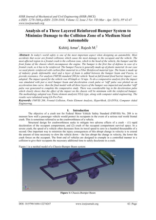
- 1. IOSR Journal of Mechanical and Civil Engineering (IOSR-JMCE) e-ISSN: 2278-1684,p-ISSN: 2320-334X, Volume 12, Issue 2 Ver. VII (Mar - Apr. 2015), PP 42-47 www.iosrjournals.org DOI: 10.9790/1684-12274247 www.iosrjournals.org 42 | Page Analysis of a Three Layered Reinforced Bumper System to Minimize Damage to the Collision Zone of a Medium Sized Automobile Kshitij Amar1 , Rajesh M.2 Abstract: In today's world safety is one of the most important aspect when designing an automobile. Most accidents that occur are frontal collisions which cause the most damage to the occupant and the vehicle. The most affected region in a frontal crash is the collision zone, which is the hood of the vehicle, the bumper and the front frame of the chassis which encompasses the engine. The bumper is the first line of defense in case of a frontal crash, so it has to be reinforced. The bumper Fascia is generally made up of plastic material. In our case we used plastic reinforced with carbon fiber material in a Fiber Reinforced material type. The beam is made up of industry grade deformable steel and a layer of foam is added between the bumper beam and Fascia, to provide resistance. For analysis FMVSS standard 208 for vehicle 'head on full frontal-fixed barrier impact', was adopted. The impact speed for the vehicle was 48 kmph or 14 mps. To do a comparative analysis first the impact was simulated with just a steel bumper beam and deceleration crash pulse or 'stiff' pulse was plotted on an acceleration time curve; then the final model with all three layers of the bumper was impacted and another 'stiff' pulse was generated to complete the comparative study. There was considerable lag in the deceleration pulse which clearly shows that the effect of the impact on the chassis will be minimum with the reinforced bumper. The methodology adopted was Finite element analysis( FEA) type, along with computer aided engineering. The results were tabulated using LS-Pre-Post. Keywords: FMVSS 208, Frontal Collision, Finite Element Analysis, HyperMesh, LS-DYNA, Computer Aided Engineering. I. Introduction The objective of a crash test for Federal Motor Vehicle Safety Standard (FMVSS) No. 208 is to measure how well a passenger vehicle would protect its occupants in the event of a serious real world frontal crash. This is sometimes referred to as the crashworthiness of a vehicle. Structural design for crashworthiness seeks to mitigate two adverse effects of a crash – (1) rapid deceleration of the occupant compartment, and (2) crush of the occupant compartment survival space. In a severe crash, the speed of a vehicle often decreases from its travel speed to zero in a hundred thousandths of a second. One important way to minimize the injury consequences of this abrupt change in velocity is to extend the amount of time necessary to slow the vehicle down – the less abrupt the change in velocity, the lower the crash forces on the occupant. The front end of vehicles are designed to crumple in a controlled manner in a collision to give their occupants the necessary additional time to safely decelerate in a crash. Figure 1 is a meshed model of a Chassis-Bumper Beam system: Figure 1: Chassis-Bumper Beam
- 2. Analysis of a Three Layered Reinforced Bumper System to Minimize Damage to the Collision… DOI: 10.9790/1684-12274247 www.iosrjournals.org 43 | Page And Figure 2 is a meshed model of a Chassis-Reinforced Bumper system: Figure 2: Chassis-Reinforced bumper system Chassis-Reinforced Bumper System: The Chassis is made up of Rigid steel i.e MATL20 (Nomenclature according to the LS-DYNA card images) and the bumper beam is made up of deformable MATL1 material. The frontal beam of the chassis is what represents the collision zone. The impact that occurs on the collision zone should be minimum whilst the bumper should absorb the maximum damage. See table 1 for detailed material properties. To create a connection between a rigid and deformable material, we created extra nodes between the connectors of the chassis and the bumper, as it is not possible to weld a rigid material to a deformable one. Reinforced Bumper: The reinforced Bumper composed of the Bumper Fascia that was made up of Carbon fiber reinforced plastic. The second layer was of Polyurethane Foam and the Bumper Beam was made up of deformable steel. The material properties are mentioned in the Table 1. Material Density (tonne/mm3 ) Modulus of Elasticity Poisson's Ratio Carbon Fiber Reinforced Plastic (MATL1) 1.8e-009 285000 0.45 Polyurethane Foam(MATL57_58) 6e-10 1 - Deformable steel(MATL1) 7.9e-009 210000 0.3 Rigid steel(MATL20) 7.8e-009 21000 0.3 Table 1: Material properties for different layers of bumper II. Methodology Rigid Wall: A rigid wall was created 50 mm from the bumper and the impact speed according to the FMVSS standard 208 for 'head on full frontal-fixed barrier impact' was to be taken at 48 kmph or 14 mps. Figure 3 clearly shows the rigid wall. Figure 3: Rigid wall at 50 mm distance from bumper
- 3. Analysis of a Three Layered Reinforced Bumper System to Minimize Damage to the Collision… DOI: 10.9790/1684-12274247 www.iosrjournals.org 44 | Page First the Bumper beam without any reinforcement was impacted on the rigid wall to see the impact damage and deceleration plots. Figure 4 shows the impact fringe levels. Figure 4: Bumper Beam crash simulation Now figure 5 shows the resultant acceleration plot of the impact pulse or 'stiff' pulse generated. The peak value stands at 4 e+06 which is very high and will have heavy impact on the collision zone of the chassis. Two nodes were selected on the chassis to study the aforementioned acceleration pulse. Figure 5: Resultant acceleration for Bumper Beam impact For the simulation to be successful, the total energy should remain constant. Figure 6 shows the Kinetic, Internal and total energy of the Chassis-Bumper System. Figure 6: Energy plot for the model
- 4. Analysis of a Three Layered Reinforced Bumper System to Minimize Damage to the Collision… DOI: 10.9790/1684-12274247 www.iosrjournals.org 45 | Page Figure 7 shows the sudden deceleration in X-direction which has to be reduced even further so that the damage on the occupant compartment is minimized. Figure 7: Deceleration pulse in X-direction for bumper beam Bumper Fascia and Foam Reinforcement If we reduce the Deceleration pulse in x direction by -1.5 e+06 to -2 e+06 and the resultant acceleration pulse by 1 e+06 to 1.5 e+06, then it will give ample time for the bumper to absorb the energy and minimum damage will occur to the occupant compartment. Figure 8 shows the reinforcement provided to the Bumper Beam. The reinforcement absorbs most of the damage due to impact and hence the deceleration is gradual, which helps in protecting the occupant compartment. Figure 8 shows the Carbon fiber reinforced plastic (in red) and Polyurethane foam (in blue). Figure 8: Carbon Fiber reinforced Bumper Fascia (in red) and Polyurethane foam reinforcement (in blue). Now, with the same impact parameters, the Chassis-Reinforced bumper system is again impacted, the simulation of which is shown in figure 9. Figure 9: Reinforced Bumper Beam crash simulation
- 5. Analysis of a Three Layered Reinforced Bumper System to Minimize Damage to the Collision… DOI: 10.9790/1684-12274247 www.iosrjournals.org 46 | Page The resultant acceleration and X-direction deceleration plots for the reinforced bumper beam crash have been plotted, which are shown by figure 10 and 12 respectively. And the energy plot for the reinforced model is given figure 11. Figure 10: Resultant acceleration for Reinforced Bumper Beam impact. Figure 11: Energy plot for the reinforced model. Figure 12: Deceleration pulse in X-direction for reinforced bumper beam III. Results As can be clearly seen from the above analysis, that the deceleration pulse has been considerably dragged and the resultant acceleration has been reduced almost by half; these values indicate that because of the drag in deceleration, the occupant compartment won't suffer sudden impact pulse, which could cause the occupant severe damage or trauma, as was the case with a non-reinforced bumper beam. The comparative results have been given in Table 2. Type Resultant Acceleration X-direction deceleration Remarks Non-Reinforced Bumper Beam 4 e+06 -1.25 (± 0.2) e+06 Occupant compartment suddenly decelerated; high chance of trauma and/or injury Reinforced Bumper Beam 2.5 (±0.25) e+06 -2.7 (±0.2) e+06 Occupant compartment deceleration slow; Low chance of occupant trauma and/or injury Table 2: Results of analysis
- 6. Analysis of a Three Layered Reinforced Bumper System to Minimize Damage to the Collision… DOI: 10.9790/1684-12274247 www.iosrjournals.org 47 | Page IV. Conclusion The current frontal impact protection that is employed in many vehicles in India and other Asian countries poses a high risk to human life. Our research clearly shows that reinforcement can be employed to the Bumper or the collision zone of the automobile can be elongated to reduce the deceleration pulse. Following the bylaws laid down by national traffic highway safety administration (NHTSA), even the slightest changes can cause huge difference and protect human life in times of road accidents. References [1]. "Shock absorbing bumper." U.S. Patent 3,666,310, issued May 30, 1972. [2]. Weisman, Morey. "Modified low-density polyurethane foam body." U.S. Patent No. 5,418,257. 23 May 1995. [3]. "Updated review of potential test procedures for FMVSS no. 208" prepared by the Office of Vehicle Safety Research [4]. Hambali, A., et al. "Material selection of polymeric composite automotive bumper beam using analytical hierarchy process." Journal of Central South University of Technology 17.2 (2010): 244-256. [5]. Balasubramaniam, R. Callister's Materials Science And Engineering: Indian Adaptation (W/Cd). John Wiley & Sons, 2009.