SlideShare a Scribd company logo
1 of 9
Download to read offline
The International Journal Of Engineering And Science (IJES)
|| Volume || 4 || Issue || 5 || Pages || PP.58-66|| 2015 ||
ISSN (e): 2319 – 1813 ISSN (p): 2319 – 1805
www.theijes.com The IJES Page 58
 Numerical Simulation of Bumper Impact Analysis and To
Improve Design for Crash Worthiness
Niketa Kankariya , Dr. F.B.Sayyad
Department of Mechanical Engineering, Genba Sopanroa Moze College of engineering pune
------------------------------------------------------------- ABSTRACT-------------------------------------------------------
The major concern in design of bumper is their potentiality to bear impact loads. Therefore, bumper impact test
is required to fulfill the safety requirement. In development of bumper systems for the automotive industry,
iterative Finite Element (FE) simulations are normally used to find a bumper design that meets the
requirements of crash performance. The crash performance of a bumper system is normally verified by results
from standardized low speed crash tests based on common crash situations. Explicit finite element method is
used to investigate stress and effective plastic strain of bumper at impact. Design modification is applied to the
bumper to improve its impact performance.
Keywords - Bumper impact, finite element analysis, effective plastic strain.
---------------------------------------------------------------------------------------------------------------------------------------
Date of Submission: 23-May-2015 Date of Accepted: 05-June-2015
--------------------------------------------------------------------------------------------------------------------------------------
I. INTRODUCTION
An automobile's bumper is the front-most or rear-most part, ostensibly designed to allow the car to
sustain an impact without damage to the vehicle's safety systems. They are not capable of reducing injury to
vehicle occupants in high-speed impacts, but are increasingly being designed to mitigate injury to pedestrians
struck by cars. Front and rear bumpers became standard equipment on all cars in 1925. What were then simple
metal beams attached to the front and rear of a car have evolved into complex, engineered components that are
integral to the protection of the vehicle in low-speed collisions. Car accidents are happening every day. Most
drivers are convinced that they can avoid such troublesome situations. Nevertheless, we must take into account
the statistics – ten thousand dead and hundreds of thousands to million wounded each year. These numbers call
for the necessity to improve the safety of automobiles during accidents. Automotive bumper system is one of the
key systems in passenger cars. Bumper systems are designed to prevent or reduce physical damage to the front
or rear ends of passenger motor vehicles in collision condition. They protect the hood, trunk, grill, fuel, exhaust
and cooling system as well as safety related equipment such as parking lights, headlamps and taillights, etc. A
good design of car bumper must provide safety for passengers and should have low weight. Different countries
have different performance standards for bumpers. Under the International safety regulations originally
developed as European standards and now adopted by most countries outside North America, a car's safety
systems must still function normally after a straight-on pendulum or moving-barrier impact of 4 km/h (2.5 mph)
to the front and the rear, and to the front and rear corners of 2.5 km/h (1.6 mph) at 45.5 cm (18 in) above the
ground with the vehicle loaded or unloaded. In North America (FMSS: Federal Motor Vehicle Safety Standards)
and Canada (CMVSS: Canadian Motor Vehicle Safety Standards), it should be meet 4KMPH pendulum and
barrier impacts.
II. IMPACT ANALYSIS BACKGROUND
In engineering practice, impacted systems present a complexity of geometry, stiffness, mass distributions,
contact areas and impact angles that are impossible to analyze and design with the traditional impact dynamics
methods. Therefore, using the knowledge of traditional method in finite element analysis will help to solve the
engineering problems. Some traditional methods are:
2.1 Stereomechanics
This method uses the conservation of energy and momentum laws along with the impulse-momentum law. For
collisions where energy is dissipated, the method uses the coefficient of restitution. The coefficient of restitution
(e) is used to relate the effect between the pre and post-impact velocities as the result of energy dissipation and
is given by
Numerical Simulation of Bumper…
www.theijes.com The IJES Page 59
V
f
e =
V
i
(1)
The coefficient of restitution is a dimensionless parameter ranging from 0 to 1 with e =0 representing a perfect
plastic and e =1 representing rigid body or perfectly-elastic impact. The COR is not a material property, but
varies with the material types impacted, impact velocities and surface geometry.
2.2 Stress-Wave Impact Approach
Stress wave theory addresses the phenomenon when a striker strikes elastic solid. At impact, a strain wave is
initiated at the contact region and transverses or radiates throughout the solid at a velocity of
1
2
E

 
 
 
, the speed
of sound in a solid where E is the Young’s modulus and ρ is the mass density of the struck material. As time
progresses, these original waves contact the boundary surfaces of the solid and reflect inward. This generates
standing or interfering strain waves, which produce the larger strains and stresses associated with impact
condition than that of ordinary static loading.
2.3 Energy Method Approach
The basis for the method is that mechanical energy is conserved. The potential and kinetic energies of the striker
are converted into strain energy, which is stored within the struck system or structure. The maximum deflections
and stresses of the impacted system occur when the velocity of the striker becomes zero when all of the striker’s
energy has transferred to the target. Equating the striker’s energy to the system’s strain energy yields the
maximum deflection of the system.
1 12 2
m v = k δ m
2 2
(2)
m
δ = vm
k
(3)
Eq. (3) indicates that the dynamic deflection m
 of the mechanical system can be determined.
III. FINITE ELEMENT ANALYSIS
A general-purpose commercial explicit finite element code, HyperMesh and LS-Dyna is applied to conduct the
dynamic impact test simulations. The FEA model of tire and wheel used in this study is constructed based on the
geometry. A full 3-D solid model consisting of six portions, namely front panel, side panel, bracket, supporting
bracket, chassis parts is constructed for the dynamic impact test simulation. The schematic of an FEA model
used in dynamic impact test simulations is shown in figure 1 and figure 2 respectively.
Table 1. Bumper Part list
Sr. no. Part/ component
name
Model
Thickness
1 Front panel 1.60mm
2 Side panel 1.60mm
3 Bracket 4.00mm
4 Supporting bracket 12.00mm
5 Chassis parts 10.00mm
Numerical Simulation of Bumper…
www.theijes.com The IJES Page 60
Figure 2. Finite Element Model of Bumper
3.1 Mesh Convergence
Figure 3. Maximum displacement at contact point for various mesh size
In order to assure the mesh model is accurate enough, a mesh convergence has been studied to ensure that the
displacement at the contact point between the striker and bumper is convergent. In figure 3 the abscissa
represents the element number of model. It shows that the maximum displacement response at the contact point
is almost convergent for mesh size 12 mm. In this study, the simulation model for bumper is constructed by
mesh size 12 mm. Bumper model is meshed with about 21068 nodes and 20382 elements.
3.2 Material Properties
The material properties of bumper that is widely used in automotive engineering industry was considered in the
FE simulation. Mechanical properties of steel are given in table 2. A nonlinear elastic–plastic material model
was used to describe the material behavior of bumper in the dynamic analyses. The true stress–strain curve of
the soft steel and hard steel is plotted in figure 4. True stress–strain material data are required for input into the
finite element model. The engineering stress–strain curve data were converted into the true stress–strain curve
data and then imported into the FEA model. Figure 4 shows true stress-strain curve.
Table 2 Material Properties of Bumper
Modulus
of
Elasticity
(N/mm2
)
Poisson’s
Ratio
Yield
Strength
(N/mm2
)
Ultimate
Strength
(N/mm2
)
Fracture
Strain
210000 0.3 350 650 0.21
σ = σ (1 + ε )en g g en g gtru e (4)
ε = ln (1 + ε )en g gtru e (5)
Equation (4) and (5) are used to calculate true stress-strain values for steel.
13.4
13.6
13.8
14
14.2
14.4
14.6
14.8
15
0 10000 20000 30000
Displacement(mm)
Element Number
Numerical Simulation of Bumper…
www.theijes.com The IJES Page 61
Figure 4. True Stress-Strain curve
3.3 Loading and Boundary Condition
To carry out impact analysis of bumper system within framework of FEA, this is low speed impact(4kmph) and
as per standards bumper should withstand it. Appropriate contacts have been defined at appropriate locations
between different parts. Fig. 5 shows loads and boundary conditions. Boundary conditions are reference for
problem solving in analysis. This deals with constraining (fixing) the model, application of loads, giving proper
contacts etc. . Here we are provided with the constrained conditions, mass of vehicle which is about 887 kg and
velocity of impact which is 10m/sec. bolt connections are given by beams and proper constraints are applied.
The constrained model appears as shown in figure 5. The velocity is given to the impactor through contacts
defined between bumper and impactor. The mass of vehicle here is considered during impact conditions.
Contacts are defined via elements as shown in figure 5.
Figure 5. Constrained Bumper Model
The failure criterion to assess the bumper impact characteristics for the FEA simulation is on the basis of a
fracture strain criterion. Such a criterion considers the failure of bumper when the calculated equivalent plastic
strain exceeds the critical plastic strain of the material.
2 2 2 2
ε = (ε - ε ) + (ε - ε ) + (ε - ε )p p 1 p 2 p 2 p 3 p 3 p 1
3
(6)
Where, subscripts (1, 2, 3) indicate the three axes corresponding to the three principal directions. The critical
plastic strain is assumed to be the percent elongation, that is, the fracture strain. The critical value is
ε = 0.21 m m / m mc (7)
IV. RESULT AND DISCUSSION
4.1 Existing Bumper Model:
Explicit finite element analysis carried out for 100 millisecond and the results were recorded at 5
millisecond time interval. For the FE model of bumper makes instant contact with the impactor at a velocity of
10 mm/ms. The plastic strain results for bumper original model are as shown below
0
0.1
0.2
0.3
0.4
0.5
0.6
0 0.05 0.1 0.15 0.2 0.25
Stress(GPa)
Strain
Soft_Mat
Hard_Mat
Numerical Simulation of Bumper…
www.theijes.com The IJES Page 62
4.1.1 Bumper Front Panel:
Figure 6. Contour plot of effective plastic strain values for Bumper Front panel.
From figure 6 the maximum effective plastic strain value for bumper front panel is 0.54 which is more than
permissible limit hence the design for Bumper frontal panel is not safe.
4.1.2. Bumper Side Panel:
Figure 7. Contour plot of effective plastic strain values for Bumper Side panel.
From figure 7 the maximum plastic strain value for bumper Side panel is 0.18 which is less than permissible
limit hence the design for Bumper side panel is safe.
4.1.3. Bumper Bracket:
Figure 8. Contour plot of effective plastic strain values for Bumper Bracket
From figure 8 the maximum plastic strain value for bumper bracket is 0.34 which is more than permissible limit
hence the design for Bumper side panel is not safe and the effective plastic strain value need to be brought
within permissible range.
Numerical Simulation of Bumper…
www.theijes.com The IJES Page 63
4.1.4 Bumper Supporting Bracket:
Figure 9. Contour plot of effective plastic strain values for supporting Bracket
From figure 9 the maximum plastic strain value for bumper supporting Bracket is 0.19 which is less than (0.22)
permissible limit hence the design for Bumper supporting Bracket is safe.
4.1.5 Chassis Section:
Figure 10. Contour plot of effective plastic strain values Chassis section
From figure 10 the maximum plastic strain value for bumper Chassis section is 0.0032 which is less than
permissible limit hence the design for Bumper Chassis section is safe.
From above plots it has to conclude that Bumper bracket exceeds the effective permissible strain value hence
some necessary changes should be made in assembly to bring the plastic strain values in the permissible limit so
that design is safe.
Possible solutions
1] Change in design of components-: we can change the design of components to get the required results. This
leads to redesigning the components by addition of ribs or change the geometry.
2] Change of material-: We can change the material of the components for proper stress distribution. We can go
for some additional composite materials to avoid the design failure.
3] Change in thickness-: we can change the thickness of components to achieve the effective plastic strain
values for the respective components. It is cost effective and time consuming way of modification.
From above we choose the first possible solution to achieve the plastic strain values and make the design safe.
Numerical Simulation of Bumper…
www.theijes.com The IJES Page 64
4.2 Modified Bumper Model:
4.2.1 Bumper Front Panel
Figure 11. Contour plot of effective plastic strain values for Bumper Front panel
The maximum plastic strain value for bumper front panel is 0.18 which is less than permissible limit hence the
design for Bumper frontal panel is safe.
4.2.2 Bumper Side panel-:
Figure 12. Contour plot of effective plastic strain values for Bumper Side panel
The maximum plastic strain value for bumper Side panel is 0.12 which is less than permissible limit hence the
design for Bumper side panel is safe.
4.2.3 Bumper Bracket-:
Figure 13. Contour plot of effective plastic strain values for Bumper Bracket
The maximum plastic strain value for bumper bracket is 0.25 which is equal to permissible limit hence the
design for Bumper side panel is safe.
Numerical Simulation of Bumper…
www.theijes.com The IJES Page 65
4.2.4 Bumper supporting Bracket-:
Figure 14. Contour plot of effective plastic strain values for supporting Bracket
The maximum plastic strain value for bumper supporting Bracket is 0.26 which is less than 0.33 permissible
limits hence the design for Bumper supporting Bracket is safe.
4.2.5 Chassis section-:
Figure 15. Contour plot of effective plastic strain values Chassis section
The maximum plastic strain value for bumper Chassis section is 0.01 which is less than permissible limit
hence the design for Bumper Chassis section is safe.
V. CONCLUSION
From above study we come to the conclusion that the permissible strain values can be achieved by adding
the stiffener to bumper components. Adding the stiffener is one of the cost effective way to get the assembly in
safety zone as compared to others such as change of material or increase in thickness. Permissible plastic strain
value results show efficient energy absorption, thus making the component assembly safe. Hence running an
analysis on explicit solver leads to cost effective way to solve the crash related problems prior to actual
production. It is observed that more kinetic-energy transfer from impactor to vehicle and less plastic strain
energy dissipates with increasing the bumper thickness. Adding stiffener to the bumper causes a rise in bumper
rigidity increasing its strength. Consequently, it results in reduction in strain values.
REFERENCES
[1] Javad Marzbanrad , Masoud Alijanpour , Mahdi Saeid Kiasat, “Design and analysis of an automotive bumper beam in low-speed
frontal crashes”, Science Direct paper, 2009, pp.902-911.
[2] Liquan Mei and C.A. Thole , “Data analysis for parallel car-crash simulation results and model optimization”, Science Direct
paper, 2007, pp. 329-337.
[3] Nader Abedrabbo and Robert Mayer, “Crash response of advanced high-strength steel tubes: Experiment and model”, Science
Direct paper, 2009, pp.1044-1057.
[4] F.Ince, H.S. Turkmen, Z. Mecitoglu, N. Uludag, I. Durgun, E. Altınok and H. Orenel , “A numerical and experimental study on
the impact behavior of box structures”, Science Direct paper , 2011, pp.1736-1741.
[5] Bryan C. Baker, Joseph M. Nolan, Brian O’Neill and Alexander P. Genetos , “Crash compatibility between cars and light trucks:
Benefits of lowering front-end energy-absorbing structure in SUVs and pickups”, Science Direct paper, 2007, pp.116-125.
[6] Tso-Liang Tenga, Fwu-An Changb, Yung-Sheng Liuc and Cheng-Ping Peng , “Analysis of dynamic response of vehicle
occupant in frontal crash using multibody dynamics method”, Science Direct paper, 2007, pp.1724-1736.
Numerical Simulation of Bumper…
www.theijes.com The IJES Page 66
[7] O.G. Lademo, T. Berstad, M. Eriksson, T. Trylan, T. Furu, O.S. Hopperstad and M. Langseth , “A model for process-based crash
simulation”, Science Direct paper, 2007, pp.376-388.
[8] Jovan Obradovic, Simonetta Boria and Giovanni Belingardi, “Lightweight design and crash analysis of composite frontal impact
energy absorbing structures”, Science Direct paper, 2011, pp.423-430.
[9] Ping Zhu, Yu Zhang, Guanlong Chen, “Metamodeling development for reliability-based design optimization of automotive body
structure”, Science Direct paper, 2011, pp.729-741.
[10] Xin Yang, Yong Xia, Qing Zhou, Pei-ChungWang and KathyWang , “ Modeling of high strength steel joints bonded with
toughened adhesive for vehicle crash simulations”, Science Direct paper, 2012, pp.21-32.

More Related Content

Viewers also liked

The Role of Artificial Intelligence and Expert Systems in the Implementation ...
The Role of Artificial Intelligence and Expert Systems in the Implementation ...The Role of Artificial Intelligence and Expert Systems in the Implementation ...
The Role of Artificial Intelligence and Expert Systems in the Implementation ...theijes
 
Smart City
Smart CitySmart City
Smart Citytheijes
 
Power Generation through the Wind Energy Using Convergent Nozzle
Power Generation through the Wind Energy Using Convergent NozzlePower Generation through the Wind Energy Using Convergent Nozzle
Power Generation through the Wind Energy Using Convergent Nozzletheijes
 
Basian-Markovian Principle in Fitting of Linear Curve
Basian-Markovian Principle in Fitting of Linear CurveBasian-Markovian Principle in Fitting of Linear Curve
Basian-Markovian Principle in Fitting of Linear Curvetheijes
 
Secure and efficient management of confidential data in the decentralized dis...
Secure and efficient management of confidential data in the decentralized dis...Secure and efficient management of confidential data in the decentralized dis...
Secure and efficient management of confidential data in the decentralized dis...theijes
 
Onto-Ethological Studies: How an Environmental Imaginary Envisions a Shared H...
Onto-Ethological Studies: How an Environmental Imaginary Envisions a Shared H...Onto-Ethological Studies: How an Environmental Imaginary Envisions a Shared H...
Onto-Ethological Studies: How an Environmental Imaginary Envisions a Shared H...theijes
 
Application of Mobile Computing In Tertiary Institutions: Case Study of Midla...
Application of Mobile Computing In Tertiary Institutions: Case Study of Midla...Application of Mobile Computing In Tertiary Institutions: Case Study of Midla...
Application of Mobile Computing In Tertiary Institutions: Case Study of Midla...theijes
 
The International Journal of Engineering and Science (The IJES)
 The International Journal of Engineering and Science (The IJES) The International Journal of Engineering and Science (The IJES)
The International Journal of Engineering and Science (The IJES)theijes
 
H021203048056
H021203048056H021203048056
H021203048056theijes
 
Study of Incidence and Etiology of Prolapse at Rural Based Teaching Hospital
Study of Incidence and Etiology of Prolapse at Rural Based Teaching HospitalStudy of Incidence and Etiology of Prolapse at Rural Based Teaching Hospital
Study of Incidence and Etiology of Prolapse at Rural Based Teaching Hospitaltheijes
 
Combinatorial Identities Related To Root Supermultiplicities In Some Borcherd...
Combinatorial Identities Related To Root Supermultiplicities In Some Borcherd...Combinatorial Identities Related To Root Supermultiplicities In Some Borcherd...
Combinatorial Identities Related To Root Supermultiplicities In Some Borcherd...theijes
 
Photocatalytic Converter
Photocatalytic ConverterPhotocatalytic Converter
Photocatalytic Convertertheijes
 
APPLYING CONCENTRATED SOLUTION OF PALM SUGAR + 5% NaCl PRIOR TO EXERCISING AN...
APPLYING CONCENTRATED SOLUTION OF PALM SUGAR + 5% NaCl PRIOR TO EXERCISING AN...APPLYING CONCENTRATED SOLUTION OF PALM SUGAR + 5% NaCl PRIOR TO EXERCISING AN...
APPLYING CONCENTRATED SOLUTION OF PALM SUGAR + 5% NaCl PRIOR TO EXERCISING AN...theijes
 
Challenges to the Implementation of It Governace in Zimbabwean Parastatals
Challenges to the Implementation of It Governace in Zimbabwean ParastatalsChallenges to the Implementation of It Governace in Zimbabwean Parastatals
Challenges to the Implementation of It Governace in Zimbabwean Parastatalstheijes
 

Viewers also liked (14)

The Role of Artificial Intelligence and Expert Systems in the Implementation ...
The Role of Artificial Intelligence and Expert Systems in the Implementation ...The Role of Artificial Intelligence and Expert Systems in the Implementation ...
The Role of Artificial Intelligence and Expert Systems in the Implementation ...
 
Smart City
Smart CitySmart City
Smart City
 
Power Generation through the Wind Energy Using Convergent Nozzle
Power Generation through the Wind Energy Using Convergent NozzlePower Generation through the Wind Energy Using Convergent Nozzle
Power Generation through the Wind Energy Using Convergent Nozzle
 
Basian-Markovian Principle in Fitting of Linear Curve
Basian-Markovian Principle in Fitting of Linear CurveBasian-Markovian Principle in Fitting of Linear Curve
Basian-Markovian Principle in Fitting of Linear Curve
 
Secure and efficient management of confidential data in the decentralized dis...
Secure and efficient management of confidential data in the decentralized dis...Secure and efficient management of confidential data in the decentralized dis...
Secure and efficient management of confidential data in the decentralized dis...
 
Onto-Ethological Studies: How an Environmental Imaginary Envisions a Shared H...
Onto-Ethological Studies: How an Environmental Imaginary Envisions a Shared H...Onto-Ethological Studies: How an Environmental Imaginary Envisions a Shared H...
Onto-Ethological Studies: How an Environmental Imaginary Envisions a Shared H...
 
Application of Mobile Computing In Tertiary Institutions: Case Study of Midla...
Application of Mobile Computing In Tertiary Institutions: Case Study of Midla...Application of Mobile Computing In Tertiary Institutions: Case Study of Midla...
Application of Mobile Computing In Tertiary Institutions: Case Study of Midla...
 
The International Journal of Engineering and Science (The IJES)
 The International Journal of Engineering and Science (The IJES) The International Journal of Engineering and Science (The IJES)
The International Journal of Engineering and Science (The IJES)
 
H021203048056
H021203048056H021203048056
H021203048056
 
Study of Incidence and Etiology of Prolapse at Rural Based Teaching Hospital
Study of Incidence and Etiology of Prolapse at Rural Based Teaching HospitalStudy of Incidence and Etiology of Prolapse at Rural Based Teaching Hospital
Study of Incidence and Etiology of Prolapse at Rural Based Teaching Hospital
 
Combinatorial Identities Related To Root Supermultiplicities In Some Borcherd...
Combinatorial Identities Related To Root Supermultiplicities In Some Borcherd...Combinatorial Identities Related To Root Supermultiplicities In Some Borcherd...
Combinatorial Identities Related To Root Supermultiplicities In Some Borcherd...
 
Photocatalytic Converter
Photocatalytic ConverterPhotocatalytic Converter
Photocatalytic Converter
 
APPLYING CONCENTRATED SOLUTION OF PALM SUGAR + 5% NaCl PRIOR TO EXERCISING AN...
APPLYING CONCENTRATED SOLUTION OF PALM SUGAR + 5% NaCl PRIOR TO EXERCISING AN...APPLYING CONCENTRATED SOLUTION OF PALM SUGAR + 5% NaCl PRIOR TO EXERCISING AN...
APPLYING CONCENTRATED SOLUTION OF PALM SUGAR + 5% NaCl PRIOR TO EXERCISING AN...
 
Challenges to the Implementation of It Governace in Zimbabwean Parastatals
Challenges to the Implementation of It Governace in Zimbabwean ParastatalsChallenges to the Implementation of It Governace in Zimbabwean Parastatals
Challenges to the Implementation of It Governace in Zimbabwean Parastatals
 

Similar to Numerical Simulation of Bumper Impact Analysis and To Improve Design for Crash Worthiness

DESIGN ANDDEVELOPMENT OF AUTOMATIC PNEUMATIC BUMPER
DESIGN ANDDEVELOPMENT OF AUTOMATIC PNEUMATIC BUMPERDESIGN ANDDEVELOPMENT OF AUTOMATIC PNEUMATIC BUMPER
DESIGN ANDDEVELOPMENT OF AUTOMATIC PNEUMATIC BUMPERIRJET Journal
 
Numerical and Theoretical Analysis for Investigation of Shear strength of A J...
Numerical and Theoretical Analysis for Investigation of Shear strength of A J...Numerical and Theoretical Analysis for Investigation of Shear strength of A J...
Numerical and Theoretical Analysis for Investigation of Shear strength of A J...ijsrd.com
 
Impact Analysis and Material Optimization of a Front Bumper in a Heavy Vehicle
Impact Analysis and Material Optimization of a Front Bumper in a Heavy VehicleImpact Analysis and Material Optimization of a Front Bumper in a Heavy Vehicle
Impact Analysis and Material Optimization of a Front Bumper in a Heavy VehicleIRJET Journal
 
IRJET-A New Approach of using Foundry Sand for Enhancing Concrete Mechanical...
IRJET-A New Approach of  using Foundry Sand for Enhancing Concrete Mechanical...IRJET-A New Approach of  using Foundry Sand for Enhancing Concrete Mechanical...
IRJET-A New Approach of using Foundry Sand for Enhancing Concrete Mechanical...IRJET Journal
 
Comparative Analysis of Behaviour of Engineering Composite Materials & their ...
Comparative Analysis of Behaviour of Engineering Composite Materials & their ...Comparative Analysis of Behaviour of Engineering Composite Materials & their ...
Comparative Analysis of Behaviour of Engineering Composite Materials & their ...paperpublications3
 
IRJET- Design and Analysis of Chassis for Solar Electric Vehicle
IRJET- Design and Analysis of Chassis for Solar Electric VehicleIRJET- Design and Analysis of Chassis for Solar Electric Vehicle
IRJET- Design and Analysis of Chassis for Solar Electric VehicleIRJET Journal
 
IRJET- Vibro Acoustic Analysis of Laminated Composite Plate Roof of Car Body
IRJET- Vibro Acoustic Analysis of Laminated Composite Plate Roof of Car BodyIRJET- Vibro Acoustic Analysis of Laminated Composite Plate Roof of Car Body
IRJET- Vibro Acoustic Analysis of Laminated Composite Plate Roof of Car BodyIRJET Journal
 
TRANSIENT ANALYSIS OF IMPACT LOADS ON BUMPER BEAM AT DIFFERENT OFFSETS
TRANSIENT ANALYSIS OF IMPACT LOADS ON BUMPER BEAM AT DIFFERENT OFFSETSTRANSIENT ANALYSIS OF IMPACT LOADS ON BUMPER BEAM AT DIFFERENT OFFSETS
TRANSIENT ANALYSIS OF IMPACT LOADS ON BUMPER BEAM AT DIFFERENT OFFSETSIAEME Publication
 
Dynamic Response Analysis of Compressor Mounting Bracket of an Automobile Veh...
Dynamic Response Analysis of Compressor Mounting Bracket of an Automobile Veh...Dynamic Response Analysis of Compressor Mounting Bracket of an Automobile Veh...
Dynamic Response Analysis of Compressor Mounting Bracket of an Automobile Veh...IRJET Journal
 
Design Optimization of Front Suspension System of a Heavy Truck using Finite ...
Design Optimization of Front Suspension System of a Heavy Truck using Finite ...Design Optimization of Front Suspension System of a Heavy Truck using Finite ...
Design Optimization of Front Suspension System of a Heavy Truck using Finite ...IRJET Journal
 
Design and Validation of a Light Vehicle Tubular Space Frame Chassis
Design and Validation of a Light Vehicle Tubular Space Frame ChassisDesign and Validation of a Light Vehicle Tubular Space Frame Chassis
Design and Validation of a Light Vehicle Tubular Space Frame ChassisIRJET Journal
 
IRJET- Design and Analysis of Bumper using Carbon Fibre 395
IRJET-  	  Design and Analysis of Bumper using Carbon Fibre 395IRJET-  	  Design and Analysis of Bumper using Carbon Fibre 395
IRJET- Design and Analysis of Bumper using Carbon Fibre 395IRJET Journal
 
IRJET- Design Analysis of a Automotive Shock Absorber Assembly
IRJET- Design Analysis of a Automotive Shock Absorber AssemblyIRJET- Design Analysis of a Automotive Shock Absorber Assembly
IRJET- Design Analysis of a Automotive Shock Absorber AssemblyIRJET Journal
 
Nonlinear static simulation of automotive bumper of a passenger car in low sp...
Nonlinear static simulation of automotive bumper of a passenger car in low sp...Nonlinear static simulation of automotive bumper of a passenger car in low sp...
Nonlinear static simulation of automotive bumper of a passenger car in low sp...eSAT Journals
 
IRJET- Side Impact Glass Fiber Composite Beam and Enhanced Passenger Car ...
IRJET-  	  Side Impact Glass Fiber Composite Beam and Enhanced Passenger Car ...IRJET-  	  Side Impact Glass Fiber Composite Beam and Enhanced Passenger Car ...
IRJET- Side Impact Glass Fiber Composite Beam and Enhanced Passenger Car ...IRJET Journal
 
IRJET- Fatigue and Static Thermal Analysis of Brake Disc for SAE based Cars
IRJET- Fatigue and Static Thermal Analysis of Brake Disc for SAE based CarsIRJET- Fatigue and Static Thermal Analysis of Brake Disc for SAE based Cars
IRJET- Fatigue and Static Thermal Analysis of Brake Disc for SAE based CarsIRJET Journal
 
IRJET- Evaluation of Fatigue Life of Suspension Knuckle using Multibody Simul...
IRJET- Evaluation of Fatigue Life of Suspension Knuckle using Multibody Simul...IRJET- Evaluation of Fatigue Life of Suspension Knuckle using Multibody Simul...
IRJET- Evaluation of Fatigue Life of Suspension Knuckle using Multibody Simul...IRJET Journal
 
Design analysis of bumper beam subjected to offset impact loading for automot...
Design analysis of bumper beam subjected to offset impact loading for automot...Design analysis of bumper beam subjected to offset impact loading for automot...
Design analysis of bumper beam subjected to offset impact loading for automot...IAEME Publication
 

Similar to Numerical Simulation of Bumper Impact Analysis and To Improve Design for Crash Worthiness (20)

H012274247
H012274247H012274247
H012274247
 
DESIGN ANDDEVELOPMENT OF AUTOMATIC PNEUMATIC BUMPER
DESIGN ANDDEVELOPMENT OF AUTOMATIC PNEUMATIC BUMPERDESIGN ANDDEVELOPMENT OF AUTOMATIC PNEUMATIC BUMPER
DESIGN ANDDEVELOPMENT OF AUTOMATIC PNEUMATIC BUMPER
 
Numerical and Theoretical Analysis for Investigation of Shear strength of A J...
Numerical and Theoretical Analysis for Investigation of Shear strength of A J...Numerical and Theoretical Analysis for Investigation of Shear strength of A J...
Numerical and Theoretical Analysis for Investigation of Shear strength of A J...
 
Impact Analysis and Material Optimization of a Front Bumper in a Heavy Vehicle
Impact Analysis and Material Optimization of a Front Bumper in a Heavy VehicleImpact Analysis and Material Optimization of a Front Bumper in a Heavy Vehicle
Impact Analysis and Material Optimization of a Front Bumper in a Heavy Vehicle
 
IRJET-A New Approach of using Foundry Sand for Enhancing Concrete Mechanical...
IRJET-A New Approach of  using Foundry Sand for Enhancing Concrete Mechanical...IRJET-A New Approach of  using Foundry Sand for Enhancing Concrete Mechanical...
IRJET-A New Approach of using Foundry Sand for Enhancing Concrete Mechanical...
 
Comparative Analysis of Behaviour of Engineering Composite Materials & their ...
Comparative Analysis of Behaviour of Engineering Composite Materials & their ...Comparative Analysis of Behaviour of Engineering Composite Materials & their ...
Comparative Analysis of Behaviour of Engineering Composite Materials & their ...
 
IRJET- Design and Analysis of Chassis for Solar Electric Vehicle
IRJET- Design and Analysis of Chassis for Solar Electric VehicleIRJET- Design and Analysis of Chassis for Solar Electric Vehicle
IRJET- Design and Analysis of Chassis for Solar Electric Vehicle
 
IRJET- Vibro Acoustic Analysis of Laminated Composite Plate Roof of Car Body
IRJET- Vibro Acoustic Analysis of Laminated Composite Plate Roof of Car BodyIRJET- Vibro Acoustic Analysis of Laminated Composite Plate Roof of Car Body
IRJET- Vibro Acoustic Analysis of Laminated Composite Plate Roof of Car Body
 
TRANSIENT ANALYSIS OF IMPACT LOADS ON BUMPER BEAM AT DIFFERENT OFFSETS
TRANSIENT ANALYSIS OF IMPACT LOADS ON BUMPER BEAM AT DIFFERENT OFFSETSTRANSIENT ANALYSIS OF IMPACT LOADS ON BUMPER BEAM AT DIFFERENT OFFSETS
TRANSIENT ANALYSIS OF IMPACT LOADS ON BUMPER BEAM AT DIFFERENT OFFSETS
 
Dynamic Response Analysis of Compressor Mounting Bracket of an Automobile Veh...
Dynamic Response Analysis of Compressor Mounting Bracket of an Automobile Veh...Dynamic Response Analysis of Compressor Mounting Bracket of an Automobile Veh...
Dynamic Response Analysis of Compressor Mounting Bracket of an Automobile Veh...
 
Design Optimization of Front Suspension System of a Heavy Truck using Finite ...
Design Optimization of Front Suspension System of a Heavy Truck using Finite ...Design Optimization of Front Suspension System of a Heavy Truck using Finite ...
Design Optimization of Front Suspension System of a Heavy Truck using Finite ...
 
Design and Validation of a Light Vehicle Tubular Space Frame Chassis
Design and Validation of a Light Vehicle Tubular Space Frame ChassisDesign and Validation of a Light Vehicle Tubular Space Frame Chassis
Design and Validation of a Light Vehicle Tubular Space Frame Chassis
 
IRJET- Design and Analysis of Bumper using Carbon Fibre 395
IRJET-  	  Design and Analysis of Bumper using Carbon Fibre 395IRJET-  	  Design and Analysis of Bumper using Carbon Fibre 395
IRJET- Design and Analysis of Bumper using Carbon Fibre 395
 
IRJET- Design Analysis of a Automotive Shock Absorber Assembly
IRJET- Design Analysis of a Automotive Shock Absorber AssemblyIRJET- Design Analysis of a Automotive Shock Absorber Assembly
IRJET- Design Analysis of a Automotive Shock Absorber Assembly
 
Nonlinear static simulation of automotive bumper of a passenger car in low sp...
Nonlinear static simulation of automotive bumper of a passenger car in low sp...Nonlinear static simulation of automotive bumper of a passenger car in low sp...
Nonlinear static simulation of automotive bumper of a passenger car in low sp...
 
IRJET- Side Impact Glass Fiber Composite Beam and Enhanced Passenger Car ...
IRJET-  	  Side Impact Glass Fiber Composite Beam and Enhanced Passenger Car ...IRJET-  	  Side Impact Glass Fiber Composite Beam and Enhanced Passenger Car ...
IRJET- Side Impact Glass Fiber Composite Beam and Enhanced Passenger Car ...
 
IRJET- Fatigue and Static Thermal Analysis of Brake Disc for SAE based Cars
IRJET- Fatigue and Static Thermal Analysis of Brake Disc for SAE based CarsIRJET- Fatigue and Static Thermal Analysis of Brake Disc for SAE based Cars
IRJET- Fatigue and Static Thermal Analysis of Brake Disc for SAE based Cars
 
IRJET- Evaluation of Fatigue Life of Suspension Knuckle using Multibody Simul...
IRJET- Evaluation of Fatigue Life of Suspension Knuckle using Multibody Simul...IRJET- Evaluation of Fatigue Life of Suspension Knuckle using Multibody Simul...
IRJET- Evaluation of Fatigue Life of Suspension Knuckle using Multibody Simul...
 
Design analysis of bumper beam subjected to offset impact loading for automot...
Design analysis of bumper beam subjected to offset impact loading for automot...Design analysis of bumper beam subjected to offset impact loading for automot...
Design analysis of bumper beam subjected to offset impact loading for automot...
 
Design analysis of bumper beam subjected to offset impact loading for automot...
Design analysis of bumper beam subjected to offset impact loading for automot...Design analysis of bumper beam subjected to offset impact loading for automot...
Design analysis of bumper beam subjected to offset impact loading for automot...
 

Recently uploaded

Gfe Mayur Vihar Call Girls Service WhatsApp -> 9999965857 Available 24x7 ^ De...
Gfe Mayur Vihar Call Girls Service WhatsApp -> 9999965857 Available 24x7 ^ De...Gfe Mayur Vihar Call Girls Service WhatsApp -> 9999965857 Available 24x7 ^ De...
Gfe Mayur Vihar Call Girls Service WhatsApp -> 9999965857 Available 24x7 ^ De...srsj9000
 
Biology for Computer Engineers Course Handout.pptx
Biology for Computer Engineers Course Handout.pptxBiology for Computer Engineers Course Handout.pptx
Biology for Computer Engineers Course Handout.pptxDeepakSakkari2
 
ZXCTN 5804 / ZTE PTN / ZTE POTN / ZTE 5804 PTN / ZTE POTN 5804 ( 100/200 GE Z...
ZXCTN 5804 / ZTE PTN / ZTE POTN / ZTE 5804 PTN / ZTE POTN 5804 ( 100/200 GE Z...ZXCTN 5804 / ZTE PTN / ZTE POTN / ZTE 5804 PTN / ZTE POTN 5804 ( 100/200 GE Z...
ZXCTN 5804 / ZTE PTN / ZTE POTN / ZTE 5804 PTN / ZTE POTN 5804 ( 100/200 GE Z...ZTE
 
OSVC_Meta-Data based Simulation Automation to overcome Verification Challenge...
OSVC_Meta-Data based Simulation Automation to overcome Verification Challenge...OSVC_Meta-Data based Simulation Automation to overcome Verification Challenge...
OSVC_Meta-Data based Simulation Automation to overcome Verification Challenge...Soham Mondal
 
Current Transformer Drawing and GTP for MSETCL
Current Transformer Drawing and GTP for MSETCLCurrent Transformer Drawing and GTP for MSETCL
Current Transformer Drawing and GTP for MSETCLDeelipZope
 
CCS355 Neural Network & Deep Learning UNIT III notes and Question bank .pdf
CCS355 Neural Network & Deep Learning UNIT III notes and Question bank .pdfCCS355 Neural Network & Deep Learning UNIT III notes and Question bank .pdf
CCS355 Neural Network & Deep Learning UNIT III notes and Question bank .pdfAsst.prof M.Gokilavani
 
HARMONY IN THE HUMAN BEING - Unit-II UHV-2
HARMONY IN THE HUMAN BEING - Unit-II UHV-2HARMONY IN THE HUMAN BEING - Unit-II UHV-2
HARMONY IN THE HUMAN BEING - Unit-II UHV-2RajaP95
 
Heart Disease Prediction using machine learning.pptx
Heart Disease Prediction using machine learning.pptxHeart Disease Prediction using machine learning.pptx
Heart Disease Prediction using machine learning.pptxPoojaBan
 
IVE Industry Focused Event - Defence Sector 2024
IVE Industry Focused Event - Defence Sector 2024IVE Industry Focused Event - Defence Sector 2024
IVE Industry Focused Event - Defence Sector 2024Mark Billinghurst
 
Internship report on mechanical engineering
Internship report on mechanical engineeringInternship report on mechanical engineering
Internship report on mechanical engineeringmalavadedarshan25
 
Software and Systems Engineering Standards: Verification and Validation of Sy...
Software and Systems Engineering Standards: Verification and Validation of Sy...Software and Systems Engineering Standards: Verification and Validation of Sy...
Software and Systems Engineering Standards: Verification and Validation of Sy...VICTOR MAESTRE RAMIREZ
 
Introduction to Microprocesso programming and interfacing.pptx
Introduction to Microprocesso programming and interfacing.pptxIntroduction to Microprocesso programming and interfacing.pptx
Introduction to Microprocesso programming and interfacing.pptxvipinkmenon1
 
Call Girls Narol 7397865700 Independent Call Girls
Call Girls Narol 7397865700 Independent Call GirlsCall Girls Narol 7397865700 Independent Call Girls
Call Girls Narol 7397865700 Independent Call Girlsssuser7cb4ff
 
Artificial-Intelligence-in-Electronics (K).pptx
Artificial-Intelligence-in-Electronics (K).pptxArtificial-Intelligence-in-Electronics (K).pptx
Artificial-Intelligence-in-Electronics (K).pptxbritheesh05
 
VIP Call Girls Service Hitech City Hyderabad Call +91-8250192130
VIP Call Girls Service Hitech City Hyderabad Call +91-8250192130VIP Call Girls Service Hitech City Hyderabad Call +91-8250192130
VIP Call Girls Service Hitech City Hyderabad Call +91-8250192130Suhani Kapoor
 
What are the advantages and disadvantages of membrane structures.pptx
What are the advantages and disadvantages of membrane structures.pptxWhat are the advantages and disadvantages of membrane structures.pptx
What are the advantages and disadvantages of membrane structures.pptxwendy cai
 
(MEERA) Dapodi Call Girls Just Call 7001035870 [ Cash on Delivery ] Pune Escorts
(MEERA) Dapodi Call Girls Just Call 7001035870 [ Cash on Delivery ] Pune Escorts(MEERA) Dapodi Call Girls Just Call 7001035870 [ Cash on Delivery ] Pune Escorts
(MEERA) Dapodi Call Girls Just Call 7001035870 [ Cash on Delivery ] Pune Escortsranjana rawat
 
Architect Hassan Khalil Portfolio for 2024
Architect Hassan Khalil Portfolio for 2024Architect Hassan Khalil Portfolio for 2024
Architect Hassan Khalil Portfolio for 2024hassan khalil
 
Sachpazis Costas: Geotechnical Engineering: A student's Perspective Introduction
Sachpazis Costas: Geotechnical Engineering: A student's Perspective IntroductionSachpazis Costas: Geotechnical Engineering: A student's Perspective Introduction
Sachpazis Costas: Geotechnical Engineering: A student's Perspective IntroductionDr.Costas Sachpazis
 

Recently uploaded (20)

Gfe Mayur Vihar Call Girls Service WhatsApp -> 9999965857 Available 24x7 ^ De...
Gfe Mayur Vihar Call Girls Service WhatsApp -> 9999965857 Available 24x7 ^ De...Gfe Mayur Vihar Call Girls Service WhatsApp -> 9999965857 Available 24x7 ^ De...
Gfe Mayur Vihar Call Girls Service WhatsApp -> 9999965857 Available 24x7 ^ De...
 
Biology for Computer Engineers Course Handout.pptx
Biology for Computer Engineers Course Handout.pptxBiology for Computer Engineers Course Handout.pptx
Biology for Computer Engineers Course Handout.pptx
 
ZXCTN 5804 / ZTE PTN / ZTE POTN / ZTE 5804 PTN / ZTE POTN 5804 ( 100/200 GE Z...
ZXCTN 5804 / ZTE PTN / ZTE POTN / ZTE 5804 PTN / ZTE POTN 5804 ( 100/200 GE Z...ZXCTN 5804 / ZTE PTN / ZTE POTN / ZTE 5804 PTN / ZTE POTN 5804 ( 100/200 GE Z...
ZXCTN 5804 / ZTE PTN / ZTE POTN / ZTE 5804 PTN / ZTE POTN 5804 ( 100/200 GE Z...
 
OSVC_Meta-Data based Simulation Automation to overcome Verification Challenge...
OSVC_Meta-Data based Simulation Automation to overcome Verification Challenge...OSVC_Meta-Data based Simulation Automation to overcome Verification Challenge...
OSVC_Meta-Data based Simulation Automation to overcome Verification Challenge...
 
Current Transformer Drawing and GTP for MSETCL
Current Transformer Drawing and GTP for MSETCLCurrent Transformer Drawing and GTP for MSETCL
Current Transformer Drawing and GTP for MSETCL
 
CCS355 Neural Network & Deep Learning UNIT III notes and Question bank .pdf
CCS355 Neural Network & Deep Learning UNIT III notes and Question bank .pdfCCS355 Neural Network & Deep Learning UNIT III notes and Question bank .pdf
CCS355 Neural Network & Deep Learning UNIT III notes and Question bank .pdf
 
HARMONY IN THE HUMAN BEING - Unit-II UHV-2
HARMONY IN THE HUMAN BEING - Unit-II UHV-2HARMONY IN THE HUMAN BEING - Unit-II UHV-2
HARMONY IN THE HUMAN BEING - Unit-II UHV-2
 
Heart Disease Prediction using machine learning.pptx
Heart Disease Prediction using machine learning.pptxHeart Disease Prediction using machine learning.pptx
Heart Disease Prediction using machine learning.pptx
 
IVE Industry Focused Event - Defence Sector 2024
IVE Industry Focused Event - Defence Sector 2024IVE Industry Focused Event - Defence Sector 2024
IVE Industry Focused Event - Defence Sector 2024
 
Internship report on mechanical engineering
Internship report on mechanical engineeringInternship report on mechanical engineering
Internship report on mechanical engineering
 
Software and Systems Engineering Standards: Verification and Validation of Sy...
Software and Systems Engineering Standards: Verification and Validation of Sy...Software and Systems Engineering Standards: Verification and Validation of Sy...
Software and Systems Engineering Standards: Verification and Validation of Sy...
 
★ CALL US 9953330565 ( HOT Young Call Girls In Badarpur delhi NCR
★ CALL US 9953330565 ( HOT Young Call Girls In Badarpur delhi NCR★ CALL US 9953330565 ( HOT Young Call Girls In Badarpur delhi NCR
★ CALL US 9953330565 ( HOT Young Call Girls In Badarpur delhi NCR
 
Introduction to Microprocesso programming and interfacing.pptx
Introduction to Microprocesso programming and interfacing.pptxIntroduction to Microprocesso programming and interfacing.pptx
Introduction to Microprocesso programming and interfacing.pptx
 
Call Girls Narol 7397865700 Independent Call Girls
Call Girls Narol 7397865700 Independent Call GirlsCall Girls Narol 7397865700 Independent Call Girls
Call Girls Narol 7397865700 Independent Call Girls
 
Artificial-Intelligence-in-Electronics (K).pptx
Artificial-Intelligence-in-Electronics (K).pptxArtificial-Intelligence-in-Electronics (K).pptx
Artificial-Intelligence-in-Electronics (K).pptx
 
VIP Call Girls Service Hitech City Hyderabad Call +91-8250192130
VIP Call Girls Service Hitech City Hyderabad Call +91-8250192130VIP Call Girls Service Hitech City Hyderabad Call +91-8250192130
VIP Call Girls Service Hitech City Hyderabad Call +91-8250192130
 
What are the advantages and disadvantages of membrane structures.pptx
What are the advantages and disadvantages of membrane structures.pptxWhat are the advantages and disadvantages of membrane structures.pptx
What are the advantages and disadvantages of membrane structures.pptx
 
(MEERA) Dapodi Call Girls Just Call 7001035870 [ Cash on Delivery ] Pune Escorts
(MEERA) Dapodi Call Girls Just Call 7001035870 [ Cash on Delivery ] Pune Escorts(MEERA) Dapodi Call Girls Just Call 7001035870 [ Cash on Delivery ] Pune Escorts
(MEERA) Dapodi Call Girls Just Call 7001035870 [ Cash on Delivery ] Pune Escorts
 
Architect Hassan Khalil Portfolio for 2024
Architect Hassan Khalil Portfolio for 2024Architect Hassan Khalil Portfolio for 2024
Architect Hassan Khalil Portfolio for 2024
 
Sachpazis Costas: Geotechnical Engineering: A student's Perspective Introduction
Sachpazis Costas: Geotechnical Engineering: A student's Perspective IntroductionSachpazis Costas: Geotechnical Engineering: A student's Perspective Introduction
Sachpazis Costas: Geotechnical Engineering: A student's Perspective Introduction
 

Numerical Simulation of Bumper Impact Analysis and To Improve Design for Crash Worthiness

  • 1. The International Journal Of Engineering And Science (IJES) || Volume || 4 || Issue || 5 || Pages || PP.58-66|| 2015 || ISSN (e): 2319 – 1813 ISSN (p): 2319 – 1805 www.theijes.com The IJES Page 58  Numerical Simulation of Bumper Impact Analysis and To Improve Design for Crash Worthiness Niketa Kankariya , Dr. F.B.Sayyad Department of Mechanical Engineering, Genba Sopanroa Moze College of engineering pune Department of Mechanical Engineering, Genba Sopanroa Moze College of engineering pune ------------------------------------------------------------- ABSTRACT------------------------------------------------------- The major concern in design of bumper is their potentiality to bear impact loads. Therefore, bumper impact test is required to fulfill the safety requirement. In development of bumper systems for the automotive industry, iterative Finite Element (FE) simulations are normally used to find a bumper design that meets the requirements of crash performance. The crash performance of a bumper system is normally verified by results from standardized low speed crash tests based on common crash situations. Explicit finite element method is used to investigate stress and effective plastic strain of bumper at impact. Design modification is applied to the bumper to improve its impact performance. Keywords - Bumper impact, finite element analysis, effective plastic strain. --------------------------------------------------------------------------------------------------------------------------------------- Date of Submission: 23-May-2015 Date of Accepted: 05-June-2015 -------------------------------------------------------------------------------------------------------------------------------------- I. INTRODUCTION An automobile's bumper is the front-most or rear-most part, ostensibly designed to allow the car to sustain an impact without damage to the vehicle's safety systems. They are not capable of reducing injury to vehicle occupants in high-speed impacts, but are increasingly being designed to mitigate injury to pedestrians struck by cars. Front and rear bumpers became standard equipment on all cars in 1925. What were then simple metal beams attached to the front and rear of a car have evolved into complex, engineered components that are integral to the protection of the vehicle in low-speed collisions. Car accidents are happening every day. Most drivers are convinced that they can avoid such troublesome situations. Nevertheless, we must take into account the statistics – ten thousand dead and hundreds of thousands to million wounded each year. These numbers call for the necessity to improve the safety of automobiles during accidents. Automotive bumper system is one of the key systems in passenger cars. Bumper systems are designed to prevent or reduce physical damage to the front or rear ends of passenger motor vehicles in collision condition. They protect the hood, trunk, grill, fuel, exhaust and cooling system as well as safety related equipment such as parking lights, headlamps and taillights, etc. A good design of car bumper must provide safety for passengers and should have low weight. Different countries have different performance standards for bumpers. Under the International safety regulations originally developed as European standards and now adopted by most countries outside North America, a car's safety systems must still function normally after a straight-on pendulum or moving-barrier impact of 4 km/h (2.5 mph) to the front and the rear, and to the front and rear corners of 2.5 km/h (1.6 mph) at 45.5 cm (18 in) above the ground with the vehicle loaded or unloaded. In North America (FMSS: Federal Motor Vehicle Safety Standards) and Canada (CMVSS: Canadian Motor Vehicle Safety Standards), it should be meet 4KMPH pendulum and barrier impacts. II. IMPACT ANALYSIS BACKGROUND In engineering practice, impacted systems present a complexity of geometry, stiffness, mass distributions, contact areas and impact angles that are impossible to analyze and design with the traditional impact dynamics methods. Therefore, using the knowledge of traditional method in finite element analysis will help to solve the engineering problems. Some traditional methods are: 2.1 Stereomechanics This method uses the conservation of energy and momentum laws along with the impulse-momentum law. For collisions where energy is dissipated, the method uses the coefficient of restitution. The coefficient of restitution (e) is used to relate the effect between the pre and post-impact velocities as the result of energy dissipation and is given by
  • 2. Numerical Simulation of Bumper… www.theijes.com The IJES Page 59 V f e = V i (1) The coefficient of restitution is a dimensionless parameter ranging from 0 to 1 with e =0 representing a perfect plastic and e =1 representing rigid body or perfectly-elastic impact. The COR is not a material property, but varies with the material types impacted, impact velocities and surface geometry. 2.2 Stress-Wave Impact Approach Stress wave theory addresses the phenomenon when a striker strikes elastic solid. At impact, a strain wave is initiated at the contact region and transverses or radiates throughout the solid at a velocity of 1 2 E        , the speed of sound in a solid where E is the Young’s modulus and ρ is the mass density of the struck material. As time progresses, these original waves contact the boundary surfaces of the solid and reflect inward. This generates standing or interfering strain waves, which produce the larger strains and stresses associated with impact condition than that of ordinary static loading. 2.3 Energy Method Approach The basis for the method is that mechanical energy is conserved. The potential and kinetic energies of the striker are converted into strain energy, which is stored within the struck system or structure. The maximum deflections and stresses of the impacted system occur when the velocity of the striker becomes zero when all of the striker’s energy has transferred to the target. Equating the striker’s energy to the system’s strain energy yields the maximum deflection of the system. 1 12 2 m v = k δ m 2 2 (2) m δ = vm k (3) Eq. (3) indicates that the dynamic deflection m  of the mechanical system can be determined. III. FINITE ELEMENT ANALYSIS A general-purpose commercial explicit finite element code, HyperMesh and LS-Dyna is applied to conduct the dynamic impact test simulations. The FEA model of tire and wheel used in this study is constructed based on the geometry. A full 3-D solid model consisting of six portions, namely front panel, side panel, bracket, supporting bracket, chassis parts is constructed for the dynamic impact test simulation. The schematic of an FEA model used in dynamic impact test simulations is shown in figure 1 and figure 2 respectively. Table 1. Bumper Part list Sr. no. Part/ component name Model Thickness 1 Front panel 1.60mm 2 Side panel 1.60mm 3 Bracket 4.00mm 4 Supporting bracket 12.00mm 5 Chassis parts 10.00mm
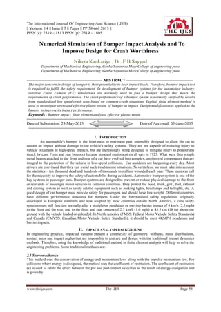
  • 3. Numerical Simulation of Bumper… www.theijes.com The IJES Page 60 Figure 2. Finite Element Model of Bumper 3.1 Mesh Convergence Figure 3. Maximum displacement at contact point for various mesh size In order to assure the mesh model is accurate enough, a mesh convergence has been studied to ensure that the displacement at the contact point between the striker and bumper is convergent. In figure 3 the abscissa represents the element number of model. It shows that the maximum displacement response at the contact point is almost convergent for mesh size 12 mm. In this study, the simulation model for bumper is constructed by mesh size 12 mm. Bumper model is meshed with about 21068 nodes and 20382 elements. 3.2 Material Properties The material properties of bumper that is widely used in automotive engineering industry was considered in the FE simulation. Mechanical properties of steel are given in table 2. A nonlinear elastic–plastic material model was used to describe the material behavior of bumper in the dynamic analyses. The true stress–strain curve of the soft steel and hard steel is plotted in figure 4. True stress–strain material data are required for input into the finite element model. The engineering stress–strain curve data were converted into the true stress–strain curve data and then imported into the FEA model. Figure 4 shows true stress-strain curve. Table 2 Material Properties of Bumper Modulus of Elasticity (N/mm2 ) Poisson’s Ratio Yield Strength (N/mm2 ) Ultimate Strength (N/mm2 ) Fracture Strain 210000 0.3 350 650 0.21 σ = σ (1 + ε )en g g en g gtru e (4) ε = ln (1 + ε )en g gtru e (5) Equation (4) and (5) are used to calculate true stress-strain values for steel. 13.4 13.6 13.8 14 14.2 14.4 14.6 14.8 15 0 10000 20000 30000 Displacement(mm) Element Number
  • 4. Numerical Simulation of Bumper… www.theijes.com The IJES Page 61 Figure 4. True Stress-Strain curve 3.3 Loading and Boundary Condition To carry out impact analysis of bumper system within framework of FEA, this is low speed impact(4kmph) and as per standards bumper should withstand it. Appropriate contacts have been defined at appropriate locations between different parts. Fig. 5 shows loads and boundary conditions. Boundary conditions are reference for problem solving in analysis. This deals with constraining (fixing) the model, application of loads, giving proper contacts etc. . Here we are provided with the constrained conditions, mass of vehicle which is about 887 kg and velocity of impact which is 10m/sec. bolt connections are given by beams and proper constraints are applied. The constrained model appears as shown in figure 5. The velocity is given to the impactor through contacts defined between bumper and impactor. The mass of vehicle here is considered during impact conditions. Contacts are defined via elements as shown in figure 5. Figure 5. Constrained Bumper Model The failure criterion to assess the bumper impact characteristics for the FEA simulation is on the basis of a fracture strain criterion. Such a criterion considers the failure of bumper when the calculated equivalent plastic strain exceeds the critical plastic strain of the material. 2 2 2 2 ε = (ε - ε ) + (ε - ε ) + (ε - ε )p p 1 p 2 p 2 p 3 p 3 p 1 3 (6) Where, subscripts (1, 2, 3) indicate the three axes corresponding to the three principal directions. The critical plastic strain is assumed to be the percent elongation, that is, the fracture strain. The critical value is ε = 0.21 m m / m mc (7) IV. RESULT AND DISCUSSION 4.1 Existing Bumper Model: Explicit finite element analysis carried out for 100 millisecond and the results were recorded at 5 millisecond time interval. For the FE model of bumper makes instant contact with the impactor at a velocity of 10 mm/ms. The plastic strain results for bumper original model are as shown below 0 0.1 0.2 0.3 0.4 0.5 0.6 0 0.05 0.1 0.15 0.2 0.25 Stress(GPa) Strain Soft_Mat Hard_Mat
  • 5. Numerical Simulation of Bumper… www.theijes.com The IJES Page 62 4.1.1 Bumper Front Panel: Figure 6. Contour plot of effective plastic strain values for Bumper Front panel. From figure 6 the maximum effective plastic strain value for bumper front panel is 0.54 which is more than permissible limit hence the design for Bumper frontal panel is not safe. 4.1.2. Bumper Side Panel: Figure 7. Contour plot of effective plastic strain values for Bumper Side panel. From figure 7 the maximum plastic strain value for bumper Side panel is 0.18 which is less than permissible limit hence the design for Bumper side panel is safe. 4.1.3. Bumper Bracket: Figure 8. Contour plot of effective plastic strain values for Bumper Bracket From figure 8 the maximum plastic strain value for bumper bracket is 0.34 which is more than permissible limit hence the design for Bumper side panel is not safe and the effective plastic strain value need to be brought within permissible range.
  • 6. Numerical Simulation of Bumper… www.theijes.com The IJES Page 63 4.1.4 Bumper Supporting Bracket: Figure 9. Contour plot of effective plastic strain values for supporting Bracket From figure 9 the maximum plastic strain value for bumper supporting Bracket is 0.19 which is less than (0.22) permissible limit hence the design for Bumper supporting Bracket is safe. 4.1.5 Chassis Section: Figure 10. Contour plot of effective plastic strain values Chassis section From figure 10 the maximum plastic strain value for bumper Chassis section is 0.0032 which is less than permissible limit hence the design for Bumper Chassis section is safe. From above plots it has to conclude that Bumper bracket exceeds the effective permissible strain value hence some necessary changes should be made in assembly to bring the plastic strain values in the permissible limit so that design is safe. Possible solutions 1] Change in design of components-: we can change the design of components to get the required results. This leads to redesigning the components by addition of ribs or change the geometry. 2] Change of material-: We can change the material of the components for proper stress distribution. We can go for some additional composite materials to avoid the design failure. 3] Change in thickness-: we can change the thickness of components to achieve the effective plastic strain values for the respective components. It is cost effective and time consuming way of modification. From above we choose the first possible solution to achieve the plastic strain values and make the design safe.
  • 7. Numerical Simulation of Bumper… www.theijes.com The IJES Page 64 4.2 Modified Bumper Model: 4.2.1 Bumper Front Panel Figure 11. Contour plot of effective plastic strain values for Bumper Front panel The maximum plastic strain value for bumper front panel is 0.18 which is less than permissible limit hence the design for Bumper frontal panel is safe. 4.2.2 Bumper Side panel-: Figure 12. Contour plot of effective plastic strain values for Bumper Side panel The maximum plastic strain value for bumper Side panel is 0.12 which is less than permissible limit hence the design for Bumper side panel is safe. 4.2.3 Bumper Bracket-: Figure 13. Contour plot of effective plastic strain values for Bumper Bracket The maximum plastic strain value for bumper bracket is 0.25 which is equal to permissible limit hence the design for Bumper side panel is safe.
  • 8. Numerical Simulation of Bumper… www.theijes.com The IJES Page 65 4.2.4 Bumper supporting Bracket-: Figure 14. Contour plot of effective plastic strain values for supporting Bracket The maximum plastic strain value for bumper supporting Bracket is 0.26 which is less than 0.33 permissible limits hence the design for Bumper supporting Bracket is safe. 4.2.5 Chassis section-: Figure 15. Contour plot of effective plastic strain values Chassis section The maximum plastic strain value for bumper Chassis section is 0.01 which is less than permissible limit hence the design for Bumper Chassis section is safe. V. CONCLUSION From above study we come to the conclusion that the permissible strain values can be achieved by adding the stiffener to bumper components. Adding the stiffener is one of the cost effective way to get the assembly in safety zone as compared to others such as change of material or increase in thickness. Permissible plastic strain value results show efficient energy absorption, thus making the component assembly safe. Hence running an analysis on explicit solver leads to cost effective way to solve the crash related problems prior to actual production. It is observed that more kinetic-energy transfer from impactor to vehicle and less plastic strain energy dissipates with increasing the bumper thickness. Adding stiffener to the bumper causes a rise in bumper rigidity increasing its strength. Consequently, it results in reduction in strain values. REFERENCES [1] Javad Marzbanrad , Masoud Alijanpour , Mahdi Saeid Kiasat, “Design and analysis of an automotive bumper beam in low-speed frontal crashes”, Science Direct paper, 2009, pp.902-911. [2] Liquan Mei and C.A. Thole , “Data analysis for parallel car-crash simulation results and model optimization”, Science Direct paper, 2007, pp. 329-337. [3] Nader Abedrabbo and Robert Mayer, “Crash response of advanced high-strength steel tubes: Experiment and model”, Science Direct paper, 2009, pp.1044-1057. [4] F.Ince, H.S. Turkmen, Z. Mecitoglu, N. Uludag, I. Durgun, E. Altınok and H. Orenel , “A numerical and experimental study on the impact behavior of box structures”, Science Direct paper , 2011, pp.1736-1741. [5] Bryan C. Baker, Joseph M. Nolan, Brian O’Neill and Alexander P. Genetos , “Crash compatibility between cars and light trucks: Benefits of lowering front-end energy-absorbing structure in SUVs and pickups”, Science Direct paper, 2007, pp.116-125. [6] Tso-Liang Tenga, Fwu-An Changb, Yung-Sheng Liuc and Cheng-Ping Peng , “Analysis of dynamic response of vehicle occupant in frontal crash using multibody dynamics method”, Science Direct paper, 2007, pp.1724-1736.
  • 9. Numerical Simulation of Bumper… www.theijes.com The IJES Page 66 [7] O.G. Lademo, T. Berstad, M. Eriksson, T. Trylan, T. Furu, O.S. Hopperstad and M. Langseth , “A model for process-based crash simulation”, Science Direct paper, 2007, pp.376-388. [8] Jovan Obradovic, Simonetta Boria and Giovanni Belingardi, “Lightweight design and crash analysis of composite frontal impact energy absorbing structures”, Science Direct paper, 2011, pp.423-430. [9] Ping Zhu, Yu Zhang, Guanlong Chen, “Metamodeling development for reliability-based design optimization of automotive body structure”, Science Direct paper, 2011, pp.729-741. [10] Xin Yang, Yong Xia, Qing Zhou, Pei-ChungWang and KathyWang , “ Modeling of high strength steel joints bonded with toughened adhesive for vehicle crash simulations”, Science Direct paper, 2012, pp.21-32.