Improvement in the Design of the Fixture and Pattern
Internship_Report
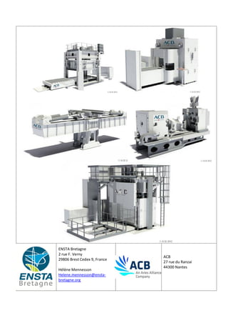
1. ENSTA Bretagne
2 rue F. Verny
29806 Brest Cedex 9, France
Hélène Mennesson
Helene.mennesson@ensta-
bretagne.org
ACB
27 rue du Ranzai
44300 Nantes
2. Internship at ACB, July 2016
Hélène Mennesson 2
Acknowledgements
The internship opportunity I had with ACB was a great chance for learning and for professional
development. I am grateful for having a warm welcome in this company thought professionals who led me
through this internship period.
I especially would like to express my deepest gratitude and special thanks to my tutor. He took time for
teaching me things. Thanks to his patience and clear explanations I had a great professional experience at the
Design Office of ACB.
3. Internship at ACB, July 2016
Hélène Mennesson 3
Sommaire
Acknowledgements............................................................................................................................................ 2
Introduction ....................................................................................................................................................... 4
1. Presentation of ACB ................................................................................................................................... 5
1.1. Aries Alliance...................................................................................................................................... 5
1.2. Main activities of ACB......................................................................................................................... 5
2. Projects and accomplishments during my internship............................................................................... 10
2.1. Conception of a protecting system in a Superplastic Forming Press (FSP) ....................................... 10
2.2. Conception of a ladder for a Longitudinal Stretch Forming Press (FEL)............................................ 13
2.3. Conception of an insulation blanket................................................................................................. 14
2.4. Additional tasks ................................................................................................................................ 15
3. Overall experience.................................................................................................................................... 17
Conclusion........................................................................................................................................................ 18
Bibliographic References.................................................................................................................................. 19
Table of figures................................................................................................................................................. 19
4. Internship at ACB, July 2016
Hélène Mennesson 4
Introduction
A la suite du stage « opérateur et découverte de l’entreprise », le stage « Assistant ingénieur», dont
ce rapport fait ici l’objet, s’inscrit dans la formation d’ingénieur. Situé entre la 2ème
année et la 3ème
année, ce
stage a pour principal objectif de « permettre à l’étudiant de confronter ses connaissances aux activités de
secteurs industriels et technologiques internationalisés correspondant aux débouchés de la formation et de
mettre en perspective ces connaissances pour la dernière phase de la professionnalisation que constitue
l’option de 3ème
année » (Stage Assistant ingénieur, Cahier des Charges, ENSTA Bretagne). Ce stage invite
aussi à la réflexion quant au projet professionnel et personnel de l’étudiant.
Ce rapport présente le stage que j’ai effectué dans le Bureau d’Etude de ACB à Nantes. Pour des
raisons de poursuite d’étude aux Etats-Unis, ce stage n’a pu être que d’une durée de 6 semaines. Néanmoins,
il a été très intense grâce à la diversité des activités qui m’ont été confiées. De nature concise, le présent
rapport recense les activités menées au cours de ces semaines. Ces activités sont essentiellement un travail
de conception 3D réalisé à l’aide du logiciel SolidWork®.
Ce rapport est composé de trois parties distinctes. La première partie est consacrée à la présentation
d’ACB, la seconde énumère mes différentes activités et enfin la dernière partie apporte une réflexion sur
mon expérience au sein d’ACB.
La rédaction de ce rapport a été faite en anglais d’une par puisque l’entreprise ACB évolue dans un
contexte internationale et d’autre part à titre d’exercice personnel en vue de mon double diplôme dans une
université Américaine.
5. Internship at ACB, July 2016
Hélène Mennesson 5
1. Presentation of ACB
1.1.Aries Alliance
Aries Alliance is a worldwide alliance of companies that include companies with acknowledge expertise in
the field of metal shaping machines and in aerospace part production.
The group is composed by four companies worldwide: ACB, Cyril Bath, Dufieux and Aries Manufacturing.
ACB, France, was created on 1st
February 2000 by the “Pressure Equipment”
Department of ALSTOM. This company is a leader in aerospace metal solutions thanks to its long experience
in the field of hydraulic presses and metal forming. ACB clients are mainly companies involved in parts for
aeronautical structures, engines aircrafts, etc.
Cyril Bath, USA, builds custom stretch forming presses for both
commercial and military aerospace applications. Through active research and development programs, the
company continues to develop innovative forming processes.
Dufieux, France, designs and builds large capacity machine-tools for milling,
pocketing and High-Speed applications. Dufieux Industrie’s sales are focused to export within the Aeronautic,
Energy and Rail-tracks sectors.
Aries Manufacturing is dedicated to the production of complex parts for the
aerospace industry. For all forming process, Aries Manufacturing is able to control the entire process, from
simulation, developments of dies, up to delivery of finished parts to its partners.
1.2.Main activities of ACB
The products and services offered to customers by ABC are the construction and installation of machines
for metal forming and turnkey workshops. Additionally it involves after-sales services and support. All the
machines are design by the Design Office of ACB and the forming process of metal are strongly studied.
1.2.1.Sheet Stretch Forming
Sheet stretch forming is a fast, economical and accurate way to form a large panel from a metal sheet. The
process consists in stretching the sheet in its plastic area and wrap it on a tool. Process simulation gives the
expected kinematic and optimizes springback.
6. Internship at ACB, July 2016
Hélène Mennesson 6
Figure 1 : Sheet Stretch Forming Principle
The two machines that allow this forming process are the Transversal Stretch Forming Press (FET) and the
Longitudinal Stretch Forming Press (FEL)
Figure 2 : Transversal Stretch Forming Press
Figure 3 : Longitudinal Stretch Forming Press
Figure 4 : Steel sheet after stretch forming process
7. Internship at ACB, July 2016
Hélène Mennesson 7
1.2.2.Profile Stretch Forming
The Swing Arm Profile Stretch Forming Press (FEV) is a machine that aims to stretch and form a profile in 2D
or 3D.
Figure 5: Swing Arm Profile Stretch Forming Press
1.2.3.Elasto-Forming
Elastoforming is an economical and high productivity forming technique to stamp shallow parts. The process
uses high pressure to press a blank into a die using flexible, high strength elastomer pads. This process is
realized by the Elastomer Matrix Forming Press (EMC).
Figure 6 : Elastomer Matrix Forming Press
8. Internship at ACB, July 2016
Hélène Mennesson 8
1.2.4.Hot Forming
Hot Forming is a forming technique with a short cycle time using medium-high temperature to increase the
formability of the material being formed. This process results in low thickness dispersion and involves
punching a sheet, followed by forming at a controlled temperature. This forming process is realized by a Hot
Forming Press (FCC)
Figure 7: Hot Forming Press
1.2.5.Super-Plastic Forming
In Superplastic Forming, a sheet of metal is clamped between a die cavity and a plate which are kept at the
convenient temperature. Gas pressure is applied to deform the sheet by forcing it against the walls of the die
cavity, under suitable stress and deformation rate. The Superplastic Forming Press (FSP) allows this type of
forming.
Figure 8: Superplatic Forming Press
9. Internship at ACB, July 2016
Hélène Mennesson 9
1.2.6.Linear Friction Welding
Linear Friction Welding is a solid state welding at forging temperature. The heat is generated by the linear
friction. Near net shape manufacturing improves buy-to-fly ratio and reduces machining costs.
Figure 9: Linear Friction Welding Machine (LFW)
10. Internship at ACB, July 2016
Hélène Mennesson 10
2. Projects and accomplishments during my internship
2.1.Conception of a protecting system in a Superplastic Forming Press (FSP)
Main Problem:
The issue concerns a FSP machine. The thermocouple box and cables carrying gas from the top of the press
ram to the tool should be protected against furnace radiation. But currently they are not. This is why the
customer asks for a design and manufacturing of a solution. Of course the design should takes into account
the environment of the machine, such as dimension, access and typical use.
The first proposition was the creation of a box made by folded steel sheet. This box, if manufactured, will be
fixed on the press ram where a free space allows a room for it. Because worker need to access to the TC box
sometimes, a door with two big handles has been design. In fact, it is important to quote that worker wear
protection clothes which are extremely cumbersome. So, the two handles have to be adapted for being
grabbed by gloves.
Figure 10 : Safety gloves
However, due to the bend radius of the gas flexible tube, we are looking for a box as deep as possible.
Therefore the two big handles are not appropriate. Thus, the primary door was modify from it first design.
The two handle are positioned in the door’s extension.
In addition, thanks to three screws and a proper clamp system, the worker could easily remove the door
without unscrewing the screws entirely.
11. Internship at ACB, July 2016
Hélène Mennesson 11
Figure 11 : Screws and Nuts - Particular attachment system
ry e
k
This new design inspires two configurations. In the first configuration, the bulkhead adapters are located on
the back of the box, thus they are totally protected from radiation. However, the bend radius of the gas tube
is quite small.
Figure 12 : Protective box-Configuration 1
In the second configuration, the bulkhead adapters are located on the left side of the box. In this case, the
door and the roof are both expanded in order to be used as deflector.
Figure 13 : Protective box- Configuration 2
These two configurations have been submit to the customer, however the « box solution » has been
refused.
12. Internship at ACB, July 2016
Hélène Mennesson 12
The other suggestion involves a sort of gutter fixed on the press ram. All gas cables will be align and carry by
the gutter form the press ram to the tool through the outside of the lateral door, hence they will be
protected from radiation.
Figure 14 : Protective Gutter system explanation
In order to attach the gutter on the press ram, we consider using screws that are already used on the press
ram. In fact, it will be easier to work on existing screws than to drill on some other place.
Figure 15 : Press Ram
For simplicity reasons during the assembly on the machine, the gutter is made in two body parts. In addition,
the fastening element will be drill during the assembly process to avoid faulty measured values.
The body of the gutter is design and optimize in accordance with the up and down movement of the press
ram.
13. Internship at ACB, July 2016
Hélène Mennesson 13
Figure 16 : Protective Gutter
2.2.Conception of a ladder for a Longitudinal Stretch Forming Press (FEL)
Main problem:
This issue focuses on a FEL machine. Due to machine maintenance, the customer would like to be able to go
inside of the machine. However the machine is about 2m deep. In addition the proposed solution should be
easily removable. In fact, technician will take care of the machine only during maintenance period.
One solution based on a ladder system has been developped but the solution was too heavy and
cumbersome. However a ladder seems appropriate for this king of application. The main subject is to find a
different geometry that could be lighter. Thus, we search for information and find a supplier who could send
us a well-suited ladder. Nevertheless, the ladder has to be fixed on the main frame of the machine. So, a
connection between the ladder and the main frame is drawn. This connection is shape according to the
frame’s geometry. As a result, the ladder is light (less than 21kg) and can be fixed and removed by only one
man. Additionally a handrail is added to the ladder for increase the safety during the ascend and descend
towards the ladder.
Figure 17 : Fastening element for the ladder
14. Internship at ACB, July 2016
Hélène Mennesson 14
Figure 18 : Ladder
2.3.Conception of an insulation blanket
Main problem:
The issue mentions a machining center composed by two machines. The customer would like to reduce the
heat loss of the warmth tool and protect the bridge cranes from radiation during the tool-changing process.
A solution with a blanket that covers the tool during the process has been considered. But the main problem
is that the tool’s dimensions could vary with the type of tool used.
The promoted solution here takes into account both big and small tools. In fact, the insulation blanket is
composed by a welded framework that supports the blanket. From the top, this support is attached to the
bridge crane by four slinging points; form below, four other slinging hold the tool. The length of these last
slinging is choosing according to the tool’s dimensions.
Figure 19 : Insulation Blancket explanation
15. Internship at ACB, July 2016
Hélène Mennesson 15
Figure 20 : Insulation Blancket
Because the eight lift loops are fix by hand, lock washer are placed between the framework and the loops.
The technology employed here is a Nord-Lock washer.
Figure 21 : Nord-Lock washer
2.4.Additional tasks
In addition to the design and conception of few systems I also perform various tasks including Translation,
update of Excel document, screws storage...
Translation
As an international company, all products are translated from French into English for all customers and
providers to understand. Thus I learnt technical vocabulary such as:
French English
usinage milling
manutention handling
soudure weld
taraudage thread
chanfrein chamfer
rondelle washer
Rainure en T T-slot
fraisage grinding
pliage bending
16. Internship at ACB, July 2016
Hélène Mennesson 16
Screws Storage
At ACB, in the Design Office, parts and assemblies are classified in a database, which is EPDM.
All screw parts are stored into different files according to its name, standards… However a lot of screws are
not well documented. This problem could create conflict in the storage, and some duplication.
That is why we firstly chose to store each screw in a proper file. However, it causes few tracking problem in
some machines. Secondly we decided to write a “technical specificity” about how to create and well-
documented a screw part. Thus I started to write a “technical specificity” about screw designation.
17. Internship at ACB, July 2016
Hélène Mennesson 17
3. Overall experience
During this internship I learnt new things.
The main thing I discover in the industry is that the most important after graduate from an engineering
school is not the ability to know theoretical formula. In fact, the most essential part is to know how to use
them in “concrete life”. For instance, I had to study an Excel table about heat transfer. Every formula about
convection, heat dissipation and radiation sound to me. Nevertheless I did not understand how these
formulae could help engineers in the mechanical dimensioning.
During this internship period, I found very interesting to be close to the assembly area. Seeing products
designed by the Design Office make it more “real”. Engineers should not be sitting behind a screen but also
be in the assembly area in order to understand how parts are assembled and how machines works for real.
Thus, I discover how concrete the engineer’s work is! Going to the assembly area helped me mastering order
of magnitude too.
As I designed few elements presented above I learnt how to master CAD software, SolidWorks®. Each
drawing tool is used for specific design. Each element is shaped according to the manufacturing process. I
learn that nothing is left to chance: each detail is analyzed in terms of conception, milling, welding, cost,
weight… Conception and design require thought.
My general knowledge has been increased too. In fact, I improved my knowledge in mechanical area. For
instance I discover specific lock washer (Nord-Lock), rules about ladder and handling system such as slinging.
Finally, this internship gives me the opportunity to live the every-day life of Design Office engineer. During six
weeks, from 8:30am to approximately 5:30pm, I leaved an engineering experience. I also learn to quickly
adopt the habit of the company. For example, everybody use the familiar “tu” form of address. Even if it was
not easy for me I finally used it.
18. Internship at ACB, July 2016
Hélène Mennesson 18
Conclusion
As a conclusion, this internship gave me the opportunity to be involved in the Design Office at ACB. It
allows me to understand how engineering training courses are applied in the industry. Thanks to this
internship, I am more familiarized with the industry and the professional world.
This internship reinforces my choice to work in the industry as a mechanical engineer. As I plan my future
career, I would say that I would firstly work in a Design Office to master every mechanical detail and then I
would go to a more managing job.