Electromagnetic relays used for power system .pptx
LEC - 2 (SUBSTATIONS).pdf
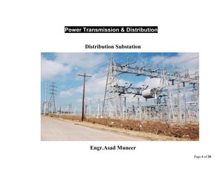
1. Page 1 of 20
Power Transmission & Distribution
Distribution Substation
Engr.Asad Muneer
2. Page 2 of 20
Learning Objectives
Distribution Substation
Substation Location
Types of Substations
Substation Equipment
3. Page 3 of 20
Distribution Substation
Substation is the assembly of apparatus used to change some characteristics of
electric power like voltage, ac to dc, frequency, P.F. etc.
4. Page 4 of 20
Substation may include following equipment: Substation transformers, Circuit
breakers, Disconnecting switches, Shunt reactors, Current transformers, Potential
transformers, Current limiting reactors, Series Capacitors, Shunt capacitors,
Grounding systems, Lighting arresters, Protective relays, Bus-bars, Insulators,
Fuses, Batteries, etc.
Functions of Substations
1. Reduce HV to low voltage.
2. Supply low voltage to local areas of distribution in which these are located.
3. Switching is done b / w different transmission lines in case of maintenance or fault.
4. Protective devices installed at substations disconnect equipment in case of fault.
5. Voltage on outgoing feeders is regulated at substation.
6. Capacitors installed at substation improve P.F. of incoming transmission line.
5. Page 5 of 20
Substation Location
• Locate S/S near to load center of its service area to provide max. Voltage due to less
distance.
• Locate S/S such that proper voltage regulation can be obtainable.
• Easy access for incoming sub-transmission lines and outgoing primary feeders.
• Enough space for future substation expansion.
• Involve minimum capital cost.
• Easily operated and maintained.
• For safety, easy access in case of abnormal occurrences.
• For reliability, good design and construction.
Types of substations
1. Generating S/S:
6. Page 6 of 20
• Associated with generating station.
• Step up (3.3 to 33 KV) to 220 or 500 KV.
• Known as UHV S/S if voltage above 400 KV.
• Known as EHV S/S if voltage between 132 KV & 400 KV.
• Reduced conductor size due to high voltage and less current.
• Less line losses (I2
R) due to less current.
2. Primary Grid S/S:
• Located at suitable load centers along the primary transmission lines.
• Step down primary transmission voltage (220-500 KV) to secondary
transmission voltage (132/66 KV).
3. Distribution S/S:
• Located at load centers.
• Step down primary dist. voltage to secondary dist. voltage (11 KV / 400 V).
7. Page 7 of 20
4. Transformer Substations:
• Change voltage from one level to other level as per needs.
• Transformer major component.
• Tapping’s may be used.
• Commonly used.
5. Switching Substations:
• Do not change voltage level.
• Perform switching operations of power lines.
6. Power Factor Correction substations:
• Improve P.F. of power system.
• Located at receiving end of transmission lines.
• Synchronous motor used to improve P.F.
8. Page 8 of 20
7. Frequency Change Substations:
• Change supply frequency.
• Frequency change required for industrial utilization.
8. Converting substations:
• Change ac power to dc power.
• Ignitron (rectifier) used.
• Traction, electroplating, electric welding, etc.
9. Industrial Substation:
• Provides supply to industrial consumers.
10. Indoor Substations:
• For 11KV & 66 KV.
• Less space required.
9. Page 9 of 20
• More time required for erection.
• Difficult future expansion.
• Difficult fault location.
• High capital cost.
• Easier operation.
• Less clearance between conductors and space.
11. Outdoor Substations:
• For voltage beyond 66 KV.
• More space required.
• Less time required for erection.
• Easy future expansion.
10. Page 10 of 20
• Easy fault location.
• Low capital cost.
• Difficult operation.
• Less possibility of fault due to greater clearance between conductors and space.
12. Underground Substation:
• In populated areas, High land cost, Security point of view, etc.
11. Page 11 of 20
13. Pole Mounted Substations:
• Installed on H-pole or 4-pole structure.
• 11 KV / 230 V, 3-phase, 4-wire.
• 11 KV line connected to transformer through gang isolator and fuses.
• Lightning arresters on H.T. side to protect substation from lightning strokes.
12. Page 12 of 20
• Oil circuit breakers installed on L.T. side automatically isolates transformer from
consumer in case of any fault.
Substation Equipment & Their Functions
1. Power Transformer: Used to step up or step down the voltages.
13. Page 13 of 20
2. Bus-Bars: Connect incoming and outgoing circuits.
3. Circuit Breaker: Automatic switching device that makes and breaks an electric
circuit under normal and abnormal circuit conditions.
4. Isolators: Disconnecting switch that disconnects circuit under no-load condition.
14. Page 14 of 20
5. Current Transformer: Used to step down currents for measurement, protection and
control purpose.
6. Potential Transformer: Used to step down voltage for measurement, protection and
control purpose.
7. Lightning Arrester (Surge Arrester): Connected between phase and ground at
substation to discharge lightning over-voltages and switching over-voltages to earth.
15. Page 15 of 20
8. Earthing Switch: Connected between line conductor and earth. Under normal
condition it is open. When line is disconnected, the earthing switch is closed to
discharge the voltages on deadlines to earth.
17. Page 17 of 20
Series Reactor:
• In order to limit the short-circuit current to a value which the circuit breakers can
handle, additional reactances known as Reactors are connected in series with the
system at suitable point.
• A reactor is a coil of number of turns designed to have a large inductance as
compared to its ohmic resistance.
• Reactors permit installation of circuit breakers of lower rating.
18. Page 18 of 20
• If fault occurs on any feeder, the voltage drop in reactor will not affect the voltage
of bus-bar and other feeders.
9. Shunt Reactor: Used to control voltage during low load periods and compensate
shunt capacitance of transmission line. It is used in EHV substations.
10. Neutral–Grounding Resistor:
• Neutral point of a 3-phase system (e.g., generator, transformer, etc) is connected
earth through a resistor, called resistance grounding.
19. Page 19 of 20
• Used to limit the earth fault current.
11. Shunt Capacitors:
• Connected in parallel with lines to supply reactive power or current required by
inductive loads to improve power factor.
• Shunt capacitors draw leading current which balances the lagging current of
inductive load current at the point of installation.
12. Series Capacitors:
• As inductance occurs in transmission lines, therefore when current flows in the
lines, voltage drop occurs.
• To compensate voltage drop, series capacitors are used for compensation of
series reactance of long lines (XL – XC).
20. Page 20 of 20
13. PLCC System (Power Line Carrier Current System):
• Used for communication, telemetry, tele-control power line carrier protection,
etc.
14. DC Batteries Sets and Battery Charges:
• Used to provide auxiliary low voltage DC supply for protective devices.