Global ereload services pvt ltd - dth tv
•
0 likes•496 views

Global eReload Services Pvt Ltd - DTH TV -Transmission and Reception - Global eReload Services Pvt Ltd is the most reliable online mobile & DTH recharge service provider in India. You can join us and start recharging all service providers' mobiles and all DTH services using a single mobile number.

Recommended
More Related Content
What's hot
What's hot (20)
Viewers also liked
Viewers also liked (17)
Similar to Global ereload services pvt ltd - dth tv
Similar to Global ereload services pvt ltd - dth tv (20)
Recently uploaded
Recently uploaded (20)
Global ereload services pvt ltd - dth tv
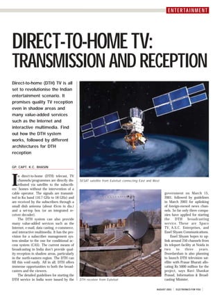
- 1. CMYK E N T E N TTEA I NIMM EN T ER RTA N E NT DIRECT-TO-HOME TV: TRANSMISSION AND RECEPTION Direct-to-home (DTH) TV is all set to revolutionise the Indian entertainment scenario. It promises quality TV reception even in shadow areas and many value-added services such as the Internet and interactive multimedia. Find out how the DTH system works, followed by different architectures for DTH reception GP. CAPT. K.C. BHASIN I n direct-to-home (DTH) telecast, TV channels/programmes are directly dis- SESAT satellite from Eutelsat connecting East and West tributed via satellite to the subscrib- ers’ homes without the intervention of a cable operator. The signals are transmit- government on March 15, ted in Ku band (10.7 GHz to 18 GHz) and 2001, followed by guidelines are received by the subscribers through a in March 2003 for uplinking small dish antenna (about 45cm in dia.) of foreign-owned news chan- and a set-top box (or an integrated re- nels. So far only three compa- ceiver decoder). nies have applied for starting The DTH system can also provide the DTH broadcasting many value-added services such as the service. These are Space Internet, e-mail, data casting, e-commerce, TV, A.S.C. Enterprises, and and interactive multimedia. It has the pro- Essel Shyam Communications. vision for a subscriber management sys- Essel Shyam hopes to up- tem similar to the one for conditional ac- link around 250 channels from cess system (CAS). The current means of its teleport facility at Noida in broadcasting in India don’t provide qual- two to three years. ity reception in shadow areas, particularly Doordarshan is also planning in the north-eastern region. The DTH can to launch DTH television sat- fill this void easily. All in all, DTH offers ellite with Prasar Bharati allo- immense opportunities to both the broad- cating Rs 5000 million for the casters and the viewers. project, says Ravi Shankar The detailed guidelines for starting the Prasad, Information & Broad- DTH service in India were issued by the DTH receiver from Eutelsat casting Minister. AUGUST 2003 ELECTRONICS FOR YOU
- 2. CMYK ENTERTAINMENT Fig. 1: Functional block diagram of a DVB-S channel varied depending on the channel environ- decoder. The DVB core system ment, it can provide this QEF rate to chan- Inner code. The data is then Generally, a digital video broadcasting nels with non-corrected error rates of 10-1 convolutionally coded depending on the (DVB) system valid for all media carries a to 10-2. The functional block diagram of a transponder size and channel quality de- flexible combination of MPEG-2 video, au- DVB-S channel is shown in Fig. 1. sired. (Increasing the code rate reduces dio, and data using the common MPEG-2 The MPEG encoder unit can take in the redundancy from the base rate. In- transport stream multiplex. The common several compressed video channels (in- creasing the code rate increases the infor- service information system gives details cluding the programme audio and other mation rate and hence the error rate but of the programmes. Modulation and addi- digital data). All the data is compressed to reduces Eb/N0 requirements.) The basic tional channel coding system, if any, are produce a single MPEG data block of 188 code rate is ½ with K=7. But this rate chosen to meet the requirements of differ- bytes. Latest MPEG encoders can compress can be increased by puncturing the code ent transmission media. A common scram- together up to ten regular video channels. at code rates of 2/3, 3/4, 5/6, 7/8, and bling system and a common conditional The whole DVB-S system operates in the others. Each code rate is tried and then access interface are available. time-division multiplexing (TDM) mode. locked using the sync data. On the re- DVB-S is the DVB standard for satel- The input data must be in 188-byte blocks ceive side, the convolutional decoder can lite delivery. It is an extension of MPEG-2 with 1-byte sync word at the beginning. take in a service quality of 10-2 and im- standard with specific instructions for Energy dispersal. The MPEG blocks prove it to an error rate of 10-4. implementing the satellite links. This stan- are shuffled to improve the output spec- Baseband pulse shaping. Baseband dard is widely adopted. trum. pulses are then gray-coded and root-raised Data coding. A Reed Solomon code cosine filtered. The roll-off rate is 0.35. (204/188) is applied to the data. This cod- QPSK modulation. This single carrier DVB-S transmission ing can correct up to eight errors. In it, 16 is now quaternary phase shift keying Many of the formats and transmission as- bytes of overhead are added to the 188 (QPSK) modulated. pects of satellite DVB services are bytes from the MPEG encoder. On the re- The table shown below provides data standardised by international bodies such ceive side, the Reed Solomon decoder can rates and transponder sizes. This is an as the International Organisation for take in data coming at a BER of approxi- example, and the parameters for individual Standardisation (ISO) and the International mately 10-4 and convert it into a BER of systems may vary. The code rate is dy- Telecommunications Union (ITU). 10-10 or lower. namically variable. So when the link is The standard developed by the Euro- Interleaving. The data is then option- clean, the transmitter may be transmitting pean Telecommunication Standard ally Fornay interleaved (convolutional in- at a high code rate (less overhead). But if Organisation (part of ITU) applies to Ku- terleaving with depth 12). It is delimited the link deteriorates, say, due to rainfall, band satellites operating at 11/12 GHz. It by occasional sync packets. On the re- the transmitter switches to a higher coder is designed to provide quasi error-free ceive side, the interleaver provides a gain rate to provide the same BER. This means (QEF) service at bit error rates (BERs) of of approximately 3 dB. This enhances the that the system must be designed to oper- 10-10 to 10-11. By using a fairly robust ability to correct burst errors that have ate in the worst condition. To guarantee a error-prevention scheme, which can be been missed by the inner convolutional certain link quality, the system must pro- vide the highest Eb/N0 listed in the table. Data Rates and Transponder Sizes Transponder QPSK Coded Convolutional Reed Information Eb/N0 Characteristics of DVB-S bandwidth symbol rate bitrate code rate Solomon bitrate (dB) carriers (MHz) (MS/s) (Mbps) code rate (Mbps) Satellite access modes. The multiple-chan- 24-27 19.5 39 5/11=0.45 188/204 16.30 4.00 nel per carrier (MCPC) mode of operation 1/2=0.50 (=0.922) 18.00 4.00 is used for transmission of a high-rate mul- 3/5=0.60 21.60 4.50 tiplex (typically, 38Mbps) comprising four 2/3=0.67 24.40 4.80 to eight standard definition digital televi- 3/4=0.75 27.00 5.00 sion programmes. Usually, such transmis- 4/5=0.80 28.80 5.60 sions use a dedicated (single-carrier) tran- 5/6=0.83 30.00 6.20 sponder. 7/8=0.88 31.40 7.00 The single-channel per carrier (SCPC) ELECTRONICS FOR YOU AUGUST 2003
- 3. CMYK ENTERTAINMENT mode of operation is used for transmis- can have a symbol rate as low as 3 MS/s, sion of a medium-rate multiplex (typically, depending upon the amount of informa- 4-8Mbps), which usually comprises a tion carried, for example, one or more single digital television programme. Such digital TV programmes. The upper limit transmissions use part of the satellite on the symbol rate extends beyond the transponder’s bandwidth and power. In lower limit for MCPC, which means that other words, the transponder is accessed the equipment capable of receiving both in the multi-carrier mode, i.e. the tran- SCPC and MCPC carriers would need to sponder resources are shared amongst sev- be able to process symbol rates over the eral users (uplink carriers). full 3-30MS/s range. The modulation, coding, and multiplex- Radiated power levels. Effective iso- ing structures of MCPC and SCPC carriers tropic radiated power (EIRP) is a measure are identical and are as specified in the of the signal strength that a satellite trans- DVB-S standard. However, SCPC and MCPC mits towards the earth below. The EIRP is transmissions differ in transmission (sym- highest at the centre of the beam and de- The Bandwidth Available and the Symbol Rate The carrier on the satellite is made up of a sequence of pulses joined together to make a continuous signal. Each pulse is a symbol. According to the modulation method, each symbol represents 1, 2, 3, etc bits of transmission rate data. In phase shift keying (PSK) modulation, each pulse is a burst of carrier signal with its sinewave-zero crossing point timing adjusted forwards or backwards in time to constitute a phase shift. Phase shifts of 180° apply in BPSK and 90° in QPSK. A phase shift of 90° represents a time shift of 1/4 of a full cycle of the sine wave. The closer the spacing phase shifts, the more difficult the distinction between them at the receive end. So for each higher-order PSK scheme, a higher carrier-to-noise ratio is required. As a general rule, if you have bandwidth to spare, use a lower-order modulation or a low- rate FEC (like 1/2 or 2/3) to spread out the signal. If you have power to spare, use a higher- order modulation and/or a higher-rate FEC (like 3/4 or 7/8). Ideally, you would want to use all of the available bandwidth and power simultaneously. If you use larger receive dishes, you will always be able to increase the system capacity. If you are doing a point-to-point link, it is worth using larger dishes. If you have thousands of receive dishes, the aggregate cost of these is significant and you will want to allow smaller sizes even though this reduces system capacity and increases space segment costs. FEC is applied to the customer’s information data at the transmit end, so transmission data rate = customer information rate x 1/FEC rate FEC rate is typically 0.5 to 0.9, so the transmission data rate is always significantly higher than the customer information rate. The symbol rate is related to other quantities as per the following relationship: SR = DR m x CRv x CRrs where SR is the symbol rate, DR is the data rate (or the customer information rate), CRv is the Viterbi FEC code rate (typically, 1/2, 2/3, 3/4, 5/6, or 7/8), CRrs is the Reed Soloman FEC code rate (typically, 168/204), and ‘m’ is the modulation factor or transmission rate bits per symbol (BPSK=1, QPSK=2, 8PSK=3, etc). On a spectrum analyser, the 3dB bandwidth is approximately the same as the symbol rate. bol) rates; radiated power levels; frequency creases at angles away from the bore-sight. accuracy, frequency stability, and phase MCPC transmissions essentially em- noise performance of reception equipment; ploy all of the available satellite tran- and ‘channel hopping’ response times. sponder power with little or no transpon- These may also employ different degrees of der ‘back-off’. (Transponder back-off forward error correction (FEC). means operation of the satellite’s high- Symbol rates (refer the box). Typi- power amplifier below its maximum out- cally, MCPC transmissions have a symbol put level in order to reduce the adverse rate of 20 to 30 symbols per second (S/ effects of channel non-linearities on the s), depending upon the bandwidth avail- transmission quality.) able for transmission. A symbol rate of SCPC transmissions share the satellite 27.5 MS/s is compatible with 33MHz sat- transponder with other SCPC transmissions ellite transponder bandwidth and is the and consequently the EIRP assigned to most commonly used. A symbol rate of each carrier is significantly less than the 30 MS/s is compatible with 36MHz tran- transponder’s maximum EIRP capability. sponder bandwidth. SCPC transmissions The back-off per carrier is at least 5 dB AUGUST 2003 ELECTRONICS FOR YOU
- 4. CMYK ENTERTAINMENT Fig. 2: Functional block diagram of a typical Ku-band satellite transmit terminal (2/3 or 1/2) in order to ture stability (<±1 to ±2 MHz over the minimise the size of the an- operating temperature range). tenna needed for service recep- Channel hopping considerations. The tion. response time during channel hopping can Frequency stability and be acceptably short with MCPC access, so phase noise considerations. long as the service information is deliv- The frequency stability and ered at an adequate rate. The maximum phase noise performance of delay is likely to occur when switching outdoor reception systems de- from one multiplex to another multiplex, signed for FM TV services may which requires retuning of the receiver to be adequate for reception of the new carrier frequency. MCPC digital TV transmissions. With SCPC access, the response time However, use of a digital-ready can be as high as 5 seconds. This is partly low-noise block converter because the data transmission rate is much (LNB) will guarantee reception lower than for MCPC transmissions, lead- of all MCPC transmissions. ing to a lower rate of service information Fig. 3: Antenna for the transmit terminal When choosing a digital-ready transfer for the same degree of overhead LNB for SCPC reception, the (percentage of the capacity allocated to and is frequently much higher, depending most important parameters to be consid- the service information). Switching be- upon the number of SCPC transmissions ered are the initial frequency accuracy and tween different multiplexes, and hence re- that share the transponder. Consequently, the temperature stability. The device ceiver retuning, will also occur more fre- for a given satellite coverage (EIRP), a should be selected for the best initial fre- quently, as SCPC transmissions will gen- larger antenna may be required to receive quency precision and the best tempera- erally carry only one or very few digital an SCPC transmission than TV programmes. is required to receive a Spectrum inversion. The MCPC transmission. It is DVB-S standard specifies the for this reason that MCPC use of QPSK for transmission access is preferred for DTH via satellite and stipulates applications. the correct way to map bits Forward error correc- from the in-phase (I) and tion. Both MCPC and SCPC quadrature (Q) baseband transmissions employ the bitstreams onto the four full range of FEC rates phase states. Whilst most specified in the DVB-S transmissions comply with standard (1/2, 2/3, 3/4, 5/ this mapping, some trans- 6, and 7/8). MCPC trans- missions are made with the missions frequently employ I and Q data streams inter- an FEC rate of 3/4 but are changed. The result is ‘spec- not constrained to do so. trum inversion’, which af- SCPC signals are transmit- fects both broadcasters and ted with a lower power and receiver manufacturers. consequently these often Spectrum inversion can be employ a higher FEC rate PanAmSat’s Castle Rock Teleport ground facility present regardless of the ac- ELECTRONICS FOR YOU AUGUST 2003
- 5. CMYK ENTERTAINMENT (a) Single-feed system (c) Switched dual-feed system (e) Mono-block system pose. Their architecture differs in cabling and signalling requirements for the con- nection between the IRD and the antenna sub-system. In Fig. 4(b), two dual-band LNBs share a common reflector. The system is intended for simultaneous reception from the satellites’ normal orbital location and a closeby orbital location (typically within ±6°). Frequency band switching and polarisation switching are performed independently within the LNB for each orbital position. Two cables are required for connection to the IRD (indoor unit), (b) Dual-feed system (d) Loop-through dual-feed system which must be equipped with two LNB inputs that can be independently Fig. 4: DTH receiver architecture controlled. Fig. 4(c) shows an alternative dual- cess mode (MCPC or SCPC). should be capable of receiving the tele- feed architecture that additionally allows Fig. 2 shows the functional block dia- cast from at least two orbital positions of switching between the two LNBs (orbital gram of a typical Ku-band satellite trans- the satellites telecasting the TV positions) to be performed at the antenna mit terminal. The antenna for the trans- programmes. Various possible architectures under the control of the IRD. Only one mit terminal is shown in Fig. 3. are discussed below. cable is required for interconnecting the Fig. 4(a) shows a single-feed system antenna sub-system and the IRD, and the for reception. It utilises a single ‘univer- IRD needs to be equipped with only a DVB-S reception sal’ LNB to receive all signals in the 10.7- single LNB input. Reception system architecture. In general, 12.75GHz range on any one of the two Fig. 4(d) shows a dual-feed architec- reception systems are of two types, namely, linear polarisations. Frequency band ture that is logically and functionally simi- individual reception systems and collec- switching and polarisation switching are lar to the architecture in Fig. 4(c), but tive reception systems. Individual recep- performed within the LNB. uses internal switching in one of the LNBs tion systems are simply referred to as DTH Figs 4(b)-(e) show systems for recep- to provide an LNB loop-through facility. It systems, while collective reception systems tion from two orbital positions via a dual- also requires a single cable for intercon- are often referred to as satellite master feed assembly. Single-antenna architec- necting the antenna sub-system and the antenna television (SMATV) systems. The tures such as these are recommended for IRD. Switching within the LNB eliminates installed reception systems should have DTH systems receiving from two orbital the need for a separate switchbox, lead- the maximum configuration flexibility, re- positions in order to avoid the cost and ing to potential cost and weight savings gardless of their architecture. environmental impact associated with in- and reducing the number of connections Given that the television services of stalling two separate antenna sub-systems. that require waterproofing. general interest exist at more than one Systems with a single mechanically Fig. 4(e) shows a mono-block univer- orbital position of a satellite, to provide steerable antenna, though having a longer sal LNB for reception from two satellites the consumers with the maximum choice response time when switching between or- spaced 6° apart. Reception is possible of programmes, DTH reception systems bital positions, would also suit this pur- across the full 10.7-12.75GHz frequency AUGUST 2003 ELECTRONICS FOR YOU
- 6. CMYK ENTERTAINMENT communication, so that the IRD can obtain feedback on the settings of re- motely configured equipment, and as a means for signaling between the outdoor and indoor units. For the pur- pose, a proprietary communication proto- col named DiSEqC (developed for Euro- pean Telecommunications Satellite Organisation) is available. The same can be requested from the Website ‘http:// www.eutelsat.com’. The output from the LNB is brought to the IRD receiver for processing. The functional block diagram of the DVB-S IRD receiver is shown in Fig. 5. Here, after RF amplification, the signal under- goes QPSK demodulation followed by er- ror correction. The demodulated output is passed through a CAS controlled decryption stage. This stage is followed by an MPEG-2 transport stream Fig. 5: Functional block diagram of DVB-S IRD receiver demultiplexer to feed the MPEG-2 based video and audio decoders as well as a band and on both polarisations from each to be directly implemented in the LNB, data interface stage. orbital position. Such devices are simpler the channel is generally received in one The audio and video outputs from the to install than equivalent systems employ- of the two frequency bands, i.e. in the respective decoders are processed by a ing two physically separate LNBs (see Figs ‘low’ frequency band (10.7–11.7 GHz) or PAL TV encoder for connection to a TV 4(b)-(d)) to achieve the same purpose. in the ‘high’ frequency band (11.7–12.75 set, VCR, or Hi-Fi audio system, as ap- These allow existing antennae receiving GHz). The LNB is switched to receive in a propriate. The data interface is used for from a single satellite position to be easily frequency band that is appropriate for the extracting any teletext and electronic upgraded for reception from two orbital desired satellite channel. programme guide (EPG) information for positions. A single cable is required for The LNB also receives on one of the use in TV/VCR. EPG is a combination of interconnecting the LNB and the IRD. This two linear polarisations, i.e. horizontal (X) hardware and software to enable viewers is the most preferred solution. or vertical (Y). It is switched to receive in to easily navigate the large number of All the architectures shown in Figs a polarisation that is appropriate for the channels and select the desired service. 4(a)-(e) require signaling from the IRD so desired satellite channel. The data stream is also interfaced, via that the appropriate frequency band and Consequently, the simplest reception modem, to a PC for e-mail, the Internet, polarisation can be selected at the antenna architecture requires four signaling states and other applications. sub-system. Depending upon the architec- to be communicated from the IRD to the ture, this can be done using either con- antenna sub-system: Challenges ahead ventional tone signalling methods or by 1. Low-band, horizontal polarisation means of a compatible communications 2. Low-band, vertical polarisation A study by European Space Agency on protocol. 3. High-band, horizontal polarisation next-generation broadcasting satellites Conventional signalling (control) 4. High-band, vertical polarisation says, “..Today, two-way satellite Internet method. Receiving systems, regardless of The conventional solution is to use service, compared to cable or DSL, is an their architecture, should operate over the continuous-tone signaling and variation of inferior service despite being overpriced full 10.7-12.75GHz frequency range and the LNB power supply voltage for this pur- and those providing two-way satellite con- on both linear polarisations (horizontal and pose. The cable that conveys the received nections are losing money. vertical) in order to receive all of the ser- satellite signals to the IRD also carries these “The main focus for future develop- vices available from one or more orbital control signals. ments in satellite broadcasting, both positions of the programme telecasting sat- The dual-feed DTH system that re- for the home and professional user ser- ellite. The simplest form of the receiver ceives from two different orbital positions vices, should be the continuous architecture consists of an antenna needs to select the appropriate feed (LNB) reduction of the cost and improvement of equipped with a single feed (LNB) and as well as the frequency band and the quality of service of two-way interac- connected by a single cable to the IRD polarisation. Additional signaling states are tive satellite connections. The first prior- (refer the DTH reception architecture of therefore required. The number of addi- ity is to prepare the advent in the Fig. 4(a)). A single LNB should work over tional states depends upon the complexity 2005-07 time frame of service bouquets the full frequency range and on both of the receive system. In general, SMATV bundling TV and light Internet services. polarisations. systems require more complex signaling To this end, efforts should be made to As the bandwidth employed by the than single-user DTH systems. reduce the cost of low-rate interactive satellite broadcasting system is too large It is also desirable to have two-way satellite terminals.” ❑ ELECTRONICS FOR YOU AUGUST 2003