Investigation of Material Removal Rate, Surface Roughness and Surface Morphol...
Development of USB with LASER
1. DTU Mechanical Engineering
Department of Mechanical Engineering
TECHNICAL REPORT
Development of USB with LASER
Design of Plastic Parts - 41737
Spring 2016
Groub 13
Daniel Sartou s090290
Gautham Ramachandren s150906
Georgios Pitsilis s152087
Piriyankan Arudselvam s152177
Sujapragash Ramesh s152182
Wahib Abboud s113161
2. Design of Plastic Parts,
S2016
2
Table of Contents
Introduction 3
1. Methods 4
1.1 Product Concept explanation 4
1.2 Functional Analysis 5
2. Product Design 6
2.1 Product geometry requirements 6
2.2 Material Selection 7
2.2.1 Detailed Material Selection 7
2.3 Functional Features 13
2.3.1 Button 13
2.3.2 Press fit 14
2.4 Computer Aided Design 16
2.4.1 USB Cap 16
2.4.2 USB Case 16
2.4.3 Cross Section 16
2.4.4 Exploded View 17
2.4.5 Final Assembly 17
2.5 Design for Manufacturing 18
3. Process Design 19
3.1 Process Parameters 27
4. Mould Design 28
4.1 3-D Models 28
4.2 Sprue 29
4.3 Runner 30
4.4 Gate 31
4.5 Ejector Placement 33
4.6 Mould design calculations: 36
References 38
3. Design of Plastic Parts,
S2016
3
Introduction
This final project has been made during a period of 8 weeks in the course: 41737 Design of Plastic
Parts at Technical University of Denmark. The overall goal is to develop a USB with an additional
function. The overall objective is to work hands-on with the product development process of a
plastic part from idea to mould design, which amongst other include clarifying product geometry
requirements, systematic material selection, design for manufacturing, calculation of functional
features, detailed graphical representation, process design and so on.
Throughout the project, different software has been used. For the material selection, CES Edupack
and CAMPUSplastics have been used to find information about materials. Autodesk Inventor has
been used to carry out the 3D and 2D drawings. Finally, Autodesk Moldflow Adviser has been used
in order to simulate the plastic injection moulding process in order to verify product design.
During the project, the group have followed the concurrent engineering development process,
where the work throughout the project has been carried out based on the methodology of
parallelization.
4. Design of Plastic Parts,
S2016
4
1. Methods
1.1 Product Concept explanation
The first step the group had to overcome were to brainstorm over which desired addition functions
the final USB product should consist. The following section briefly summarizes the different concepts
for a multifunctional USB, which the group discussed and the final concept selected for further
development. Different ideas were proposed, but only the three best ideas are listed below:
• USB-timer: an USB containing a digital front display allowing the user always to have a clock
on him, when carrying the USB, additional the clock would charge by the USB portal.
• USB-pen: a two sided USB, one side containing a pen for writing while the other side
containing the USB.
• USB Laser Pointer: same principals as the USB-pen but the pen is substituted with a laser
pointer instead.
When choosing the final concept, following considerations were taken into account:
• Simplicity of the product
• Manufacturability
• Manufacturing process and product assembling steps
These considerations narrowed the final choice of product down to the USB laser pointer and the
USB-pen, due to the USB-timer having issues with the simplicity of the product, and implementing
the digital display would increase difficulty in manufacturing the product. In terms of simplicity and
smoother design, the USB laser pointer, made it a favourable final choice over the USB pen. The
USB laser pointer would let us operate under similar dimensions and design a traditional USB case
cover. The final product concept will consist of following parts:
• Cap
• Top Case
• Bottom Case
• PCB
• Rechargeable battery
• Laser
5. Design of Plastic Parts,
S2016
5
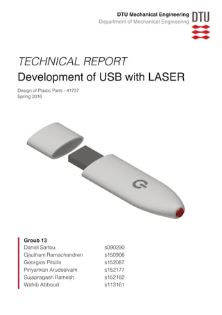
The purpose and idea behind the product is to have a compact “storage and pointing” device in one
unit. The rechargeable battery for the laser, is charged via the USB port. The button for activating
the laser is hidden beneath the top case, and only indicated by a small icon on the surface. The final
concept is presented on figure 1a.
1.2 Functional Analysis
The device consists of two functional parts; the following section will further investigate the function
of each individual part. The functional analysis will be split in two parts one concerning the laser
pointer, and the other concerning the USB storage device.
In terms of the laser pointer, following criteria is important:
• Comfort when holding the device
• Easy “one touch” laser activation option
• Clear indication of where the push button is to activate the laser
• Hidden button to limit particles to interfere with the device
• Smooth surface
• Lux rating of the laser
In terms of design choice, the lens of the laser would be set inside the cover to limit scratches and
particles interfering with the laser lens. Finally, the laser should be rechargeable by the USB storage
output.
In terms of the USB, following criteria is important:
• Dimensions predetermined for the USB
• Sweat resistance.
• Moisture resistance.
• Ability to charge the laser
Figur 1a - Final product concept
7. Design of Plastic Parts,
S2016
6
2. Product Design
2.1 Product geometry requirements
In terms of product geometry, the final product has to follow a set of criteria regarding the dimensions
of the USB; these criteria are showed on figure 2a.
In addition, following constrains must be met:
• Thickness of the green PCB: 1mm
• Largest thickness: 3.5mm
• Thickness of metal part: 4mm
Since, we have to implement an extra module containing the laser module the total length will
increase. However, it is very important to take into account the user experience of a traditional USB.
This means, it must not be too big and clumsy. Therefore, the USB must not exceed following:
• Total length: 80mm
• Total width: 8mm
Figur 2a – PCB dimension constrains
8. Design of Plastic Parts,
S2016
7
2.2 Material Selection
2.2.1 Detailed Material Selection
Having a LASER pointer attached to the USB makes it quite critical when it comes to cyclic loading
of the USB. There are numerous requirements for the product when selecting a material. But the
most important, or primary requirements for this USB design is that it should be sweat resistant,
opaque, stiff and fatigue proof. In addition, like any other USB device other requirements for the part
are biocompatibility, impact resistant, electrical insulation and have a long life cycle.
Being a handheld device, the USB will be exposed to sweat (pH of 4.5-7), so it must not degrade
over time when exposed. Also enclosing the LASER, the material must not transmit ambient light
into the chamber that interferes with the functioning and performance of the LASER. And the button
for the LASER has been designed to be concealed from being seen and underneath the surface of
one of the cases of the device. Hence the material must be stiff enough (figure 2b) that it is able to
deform elastically when pressed for more than a million cycles and yet not crack. This demands the
stiffness and fatigue strength (Appendix 1)of the part be good.
Assuming that the users will drop the device on the floor on more than 1 occasion during the life
cycle of the part, it would be safe to select a material with good impact strength(Appendix 2).
Also, when the device is used as a USB and the user detaches it from any computer, the user must
not be electrocuted. In other words, the material must be a good insulator. Another interesting feature
of the material is its operation temperature that must be up to 60o
C. Theoretically the operation
Young's modulus (GPa)
0,2 0,5 1 2 5
Yieldstrength(elasticlimit)(MPa)
10
20
50
100
Acrylonitrile butadiene styrene (ABS)
Polyoxymethylene (Acetal, POM)
Polyetheretherketone (PEEK)
Phenolics
Polypropylene (PP)
Polyethylene (PE)
Ionomer (I)
Starch-based thermoplastics (TPS)
Acrylonitrile butadiene styrene (ABS)
Figur 2b - Yield strength in function of Young’s Modulus
9. Design of Plastic Parts,
S2016
8
temperature of those devices is close to the room temperature but due to electricity consumption of
the device or of the pc, the temperature can be increased. Taking in account a normal cooling system
for a personal computer, the conducted heat can reach up to 50o
C but for safety reasons we
increased the value up to 60o
C (safety factor equal to 1.2)(figure 2c).
Figur 2c - Elongation as a function of maximum service temperature
Being held in one’s hands for long durations at a time, the material must not interfere with their health
meaning the material must also be bio compatible to an extent. Also, the material must sustain a
million cycles without significant changes in its dimensions, hence the material must also possess
good creep strength. Also, from the perspective of aesthetics, the materials must be
miscible/compatible with numerous additives for colour and other stabilisers. Also the material must
be easily injection mouldable(Appendix 3), considering the final production requirement. In addition,
it has been decided that the 2 halves of the USB case will be glued, hence the material must not
react with common adhesives.
Maximum service temperature (°C)
40 60 80 100 120 140 160 180 200 220 240 260 280
Elongation(%strain)
1
10
100
1000
Polyoxymethylene (Acetal, POM)
Cellulose polymers (CA)
Polytetrafluoroethylene (Teflon, PTFE)
Polyetheretherketone (PEEK)
Phenolics
Polystyrene (PS) Polyester
Epoxies
Polyamides (Nylons, PA)
Polycarbonate (PC)
Polypropylene (PP)
Polyethylene (PE)
Polyurethane (tpPUR)
Acrylonitrile butadiene styrene (ABS)
Ionomer (I)
Acrylonitrile butadiene styrene (ABS)
10. Design of Plastic Parts,
S2016
9
The 5 step method was used for the material selection procedure. Based on these product
requirements, numerous materials requirements were arrived and they are shown on table 2a.
Product
Requirement
Material Requirement Description
Shatter Proof Good Impact strength
So that the USB laser does not break when
dropped
Cyclic Loading Good Fatigue Strength
When the button for the LASER is repeatedly
pressed, the USB must not fail
Sweat and
water resistant
Excellent chemical
resistance
The USB when held in hand must not degrade
when exposed to the acid in perspirations
Hazard proof Biocompatibility
The laser pointer when held in hand even in the
worst case when interacting with the human
body must not harm the user’s health
Manufacturing
and assembly
flexibility
Moldability, gluing
(adhesive properties)
The material must be easily injection moldable
and easily assembled
Does not let
ambient light to
pass through
Opaque
To ensure that the ambient light does not
interfere with the operation of the LASER
Does not
conduct
electricity
Insulator
When the user handles the USB, he/she must
not be electrocuted
Stiff Optimal Young’s modulus
Due to the thickness of the product and the
desired application, the young’s modulus plays
an important role in deciding the stiffness
Long life cycle
Excellent Creep strength /
Fatigue strength
The product must retain its dimensions for at
least 3 years
Table 2a – Product requirements, material requirements and description
11. Design of Plastic Parts,
S2016
10
Based on the table 2a, the material properties were then listed into 3 categories based on the 5 step
method as:
• Category 1 – Moldability, adhesive properties, biocompatibility, chemical resistance, optical
properties, electrical conductivity
• Category 2 – Impact strength, creep strength, fatigue strength
• Category 3 – Stiffness, Cost
A number of plastic materials were available to be chosen from. But only the following amorphous
and semi crystalline plastics were chosen, for the reason that ready and reliable data was available
and also because of the fact that they are some of the commonly used polymers. And based on
categories 1 and 2, the materials were eliminated as shown on table 2b, and the materials chosen
were ABS, SB/SAN and POM, for further analysis.
Material Requirement
Amorphous Semi Crystalline
PS ABS SB/SAN PVC PMMA PC PE PP POM PA PTFE
Injection Moulding
Adhesion to glue
Additives/Colouring
Acid Resistance (10%
H₂SO₄)
Water absorption
Biocompatibility
Optical Property Tsp Op Op Tsl Tsp Tsp Tsl Tsl Op Tsl Tsl
Electrical property In In In In In In In In In In In
Strength (MPa) (Creep) 7 14 11 11 15 9 6 7 19 10 NA
Fatigue Strength (MPa at
10⁷ Cycles)
23 22 NA 26 33 31 23 17 34 66 7
Pass No Yes Yes No No No No No Yes No No
Table 2b – Comparison of polymers
Legend: Tsp – Transparent, Op – Opaque, Tsl – Translucent, In – Insulator, NA – Not Available
12. Design of Plastic Parts,
S2016
11
Most of the materials have suitable properties, but based on the optical property, creep strength and
fatigue strength desired for the part the 3 materials were chosen. The selected materials were further
filtered down based on category 3, which was based on relative cost (figure 2d) and relative stiffness
of the material.
Also the elongation must be above 2% because over this value a material can be described as non-
brittle. Here the base or reference material used was PP.
Material Requirement Amorphous Semi Crystalline
PS ABS SB/SAN PVC PMMA PC PE PP POM PA PTFE
Relative Stiffness 0.84 0.81 0.84 0.72 0.74 0.86 1.2 1 0.67 0.79 1.41
Relative Cost 11 22 14 11 19 38 9 8 26 28 NA
Passed No Yes No No No No No No No No No
Table 2c – Comparison of relative stiffness and relative cost
Using the 5 step method, it was inferred that the best material in terms of relative cost and category
3, would be ABS, as shown on table 2c. One can also argue that SB/SAN is a better choice in terms
of cost. But the creep strength (obtained by multiplying the creep modulus and the maximum
permissible deformation) of the SB/SAN is less than ABS, and that is more important on the long
run. For the simulated condition, that would yield a safety factor of almost 3. In addition, the relative
Price * density
2000 5000 10000 20000 50000 100000
Yieldstrength(elasticlimit)(MPa)
10
20
50
100
Acrylonitrile butadiene styrene (ABS)
Polytetrafluoroethylene (Teflon, PTFE)
Starch-based thermoplastics (TPS)
Polymethyl methacrylate (Acrylic, PMMA)
Phenolics
Polyethylene (PE)
Cellulose polymers (CA)
Polyamides (Nylons, PA)
Polyhydroxyalkanoates (PHA, PHB)
Polyetheretherketone (PEEK)
Ionomer (I)
Figur 2d - Yield strength in function of Density times Price
13. Design of Plastic Parts,
S2016
12
stiffness of ABS is better than SB/SAN, this would require less material for ABS for the same
stiffness, partially compensating the increased cost factor. Even though POM has better mechanical
properties than both ABS and SB/SAN, one key factor is that it is not acid resistant (sweat in this
case) as much as the others. In order to examine the cost efficiency of the materials, the Young’s
modulus compared with the embodied energy per cubic meter (Mj/kg)( energy required to produce
1 kilogram) in order to present the minimizing of the embodies energy in the polymer while providing
structural functionality, such as the Young’s modulus. Worth noticing is the comparison of the two
graphs before and after the implementation of the filters (elongation, mould ability, maximum
temperature and especially of the transparency) (Figure 2e and figure 2f).
Figur 2e – Young’s modulus as a function of embodied energy (without filters)
Figure 2f – Young’s modulus as a function of embodied energy (with filters)
Embodied energy, primary production (MJ/kg)
50 100 200
Young'smodulus(GPa)
0,2
0,5
1
2
5
Polyetheretherketone (PEEK)
Polyoxymethylene (Acetal, POM)
Acrylonitrile butadiene styrene (ABS)
Phenolics
14. Design of Plastic Parts,
S2016
13
Concerning the process, filters were used on Polymer injection moulding properties because our
process must in the most optimized way, including the mass of the USB and the maximum
thickness(Appendix 4) Thus the final processes are the following:
1. Injection blow moulding
2. Injection moulding (thermoplastics)
3. Precision glass moulding
4. Thermoforming
As it was expected the Injection moulding of the thermoplastics is located in a odd position and also
it the most widely used method to product devices like this.
2.3 Functional Features
2.3.1 Button
As mentioned earlier in the report, the button will not be visible as it is placed underneath the top
case. This means, whenever the user wants to activate the laser, a certain force is required. It must
be ensured that the force required is not higher than the strength of the material. A FEM analysis of
the USB has been performed in Autodesk Inventor to clarify whether the design will withstand a
given load condition. It has been determined to apply a force of 10N on the top case. As it can be
seen on figure 2g, maximal the Von Miss Stress is 4,78MPa, meaning the design will not fail as the
material’s strength is higher.
Figur 2g – FEM analysis
15. Design of Plastic Parts,
S2016
14
2.3.2 Press fit
In order to ensure that the protective cap does not fall off
unintendedly, small ribs are added to the design.
When the cap is squeezed onto the USB, the width of the
ribs are getting slightly deformed (compression), resulting
in a friction force.
Initially the stresses in the material are high.
σ" = E×ε (1)
While time passes, the stresses are reduced, but by lower
and lower rates. This mechanism is called relaxation.
Another similar mechanism is creep. During creep,
instead of applying a constant strain and waiting for the
stresses to decrease, a constant stress (force) is applied
and the sample will deform over time – again at slower and slower rates.
Since creep data are more commonly provided by the suppliers, it is assumed for these early
calculations that the results from the two methods are sufficiently close to one another, so that it is
safe to solve this issue as if it was creep. Furthermore it has to be assumed that neither the cap or
the USB are deflecting, as well as the ribs are not bending. A final assumption is that the data
presented, which is for tension (unless otherwise mentioned), is also applicable for compression.
Compressive Young’s Modulus and yield strength have been found for ABS[1] (unspecified grade):
E()*+ = 2,5 GPa
σ2,()*+ = 65 MPa
Inserting the values into Eq. (1) gives the highest tolerated deformation within the elastic region:
ε*56 = 2,6%
To stay within the allowed limits, a 1 % deformation during attachment of the cap is investigated.
With the earlier mentioned assumption, data of creep stress needed for a 1 % deformation to occur
after roughly 1 year (10’000 h) will be used to approximate the actual relaxation stress after the same
period of time.
Looking at isochronous stress-strain curves (aka. creep curves) for the material(figure 2i), the
deformation as a function of time and applied stress can be found. The 10’000 h curve at 1 % strain
Figur 2h – Front view(Upper) and top view(lower) of
USB inserted into the cap.
16. Design of Plastic Parts,
S2016
15
returns the stress value of 10 MPa, which
can also be expressed as the normal force
by multiplying with the area of interface
between the ribs and the USB.
F9 = σ×A (2)
Then, the friction force can be calculated
by multiplying FN with the coefficient of
friction, µs, which has the general value of
0,1-0,3 for metal against plastics.
F; = µ=×F9 or
F; = µ=×σ×A
(3)
The first simple approach of computing the area of contact involves a rib thickness of 0,15 mm, a
contact length (in the logitudinal direction) of 10 mm and 6 ribs. This results in the force required to
remove the cap:
F; =
0,1
0,3
×10 MPa×0,15 mm×10 mm×6
⇓
9 N ≤ F; ≤ 27 N
(4)
For an initial starting point, this result looks really promising, as 5 N (0,5 kg) is the lowest allowable
force.
Following is an iterative process involving customised CAD drawings of parts and moulds, injection
flow analysis, FEM simulations, DFM rules, adjustment of polymer grade and if necessary tradeoffs
in product design. Also tests to determine the actual friction coeficient between the ABS of the cap
and the metal of the USB is required to perfect the design before production of the moulds can begin.
Figur 2i – Isochronous stress-strain curves of Novodur→ P2H-
AT(23℃). Source: Campus→ 5.2 Database
17. Design of Plastic Parts,
S2016
16
2.4 Computer Aided Design
The USB design has been modelled in 3D using Autodesk Inventor. Furthermore, 2D technical
drawings has been made, which can be seen in appendix 5 and appendix 6.
2.4.1 USB Cap
2.4.2 USB Case
2.4.3 Cross Section
Figure 2j - Cap
Figure 2k - Case
Figure 2l - Vertical and horizontal cross-section view
18. Design of Plastic Parts,
S2016
17
2.4.4 Exploded View
Figure 2m - Exploded view of the USB
2.4.5 Final Assembly
Figure 2n - Final design
19. Design of Plastic Parts,
S2016
18
2.5 Design for Manufacturing
In order to ensure the USB can be manufactured easily and economically, the product design has
been designed in respect to manufacturing(DFM). Different guidelines for plastic parts, given in the
lectures, have been used as reference for designing our product [2] . Below it can be seen, which
design for manufacturing principles that has been applied for the cap and enclosure.
DFM Principle CAP Enclosure(Base + Top)
Uniform wall thickness Uniform wall thickness of 1mm has
been applied, in order to prevent
warpage.
Uniform wall thickness of 1mm
has been applied, in order to
prevent warpage.
Undercuts We have avoided undercuts as it
requires special and expensive
mould actions.
We have avoided undercuts as
it requires special and
expensive mould actions.
Draft angles Draft angles has been added on
the ribs along the demoulding
direction. The recommended
value of ≥ 0.5° has been applied.
No draft angles has been
applied as the curved profile
will generate slip angels that
will allow easy demoulding.
Corners and edges All internal and external corners
and edges have as a minimum 0.1
radius, except the front interface
surface in order to ensure a tight fit
between the cap and enclosure.
All internal and external
corners and edges have as a
minimum 0.1 radius, except
the front interface surface in
order to ensure a tight fit
between the cap and
enclosure.
Ribs Ribs, inside the cap, has been
designed with a thickness of 0.6 ∙
𝑆OPQ to avoid sink marks and
warpage.
Table 2d – Applied DFM principles
21. Design of Plastic Parts,
S2016
19
3. Process Design
Before getting to our final design and material, an iterative process with a lot of changes has been
done. Both the right design and the right commercial type of ABS plastic has been selected in the
end after a longer process with several reconsiderations. The chosen material is from Styrolution of
the type Novodur HH-106. This material has been selected based on several simulations, where
flow properties and part quality has been the main evaluation criteria. Furthermore, the final design
can be seen on Figure 3a and Figure 3b.
Figure 3a: Final Design of USB Pointer
Figure 3b: Final Design of Case and Cap
22. Design of Plastic Parts,
S2016
20
When looking on the main part, it consists of two identical halves. The gate has been placed in the
inside of the part, so the mark from the gate when the part is moulded will not affect the design.
Furthermore, the gate has been placed in the middle to obtain good flow in the part. The case was
made with a wall thickness on 0,25 mm in the beginning, which resulted in a short shot. The design
has then been changed to 1 mm thick part. This can be seen on Figure 3c and Figure 3d:
Figure 3c: Confidence of Fill for 0,25 mm Wall Thickness (Left) and 1 mm Wall Thickness (Right)
Figure 3d: Plastic Flow in 0,25 mm Wall Thickness (Left Upper) and 1 mm Wall Thickness (Other Three)
23. Design of Plastic Parts,
S2016
21
These figures from the simulations show that the case with a wall thickness of 1 mm will be filled
100% without any problems.
When looking further on the analysis, the quality of the part can be predicted. This analysis shows a
really good outcome, where only 0,79% of the part is considered to have a medium quality. The rest
is predicted to have a good quality, which means that this analysis accepts the part design. This
analysis can be seen on Figure 3e.
Figure 3e: Quality Prediction of the Case
When this part is run through the simulation software, it shows an injection pressure on 22,53 MPa,
which is the lowest pressure needed to fill the whole part. This injection pressure can be increased
as long as the shot will not create flashes.
Considering air traps and weld lines, it seems quite satisfying. There are obviously some air traps,
which have to be compensated by making air vents in the mold. The size of the air vents should be
in the manner, so the plastic cannot flow through. When looking on weld lines, we have a few ones
mostly around the cylindrical supports, which is due to that two flow fronts meet on the other side of
the injection spot. This is a normal outcome, which is not that important for this part, since it is not
exposed to high forces etc. However, there might be small visible marks at the weld lines, but this is
expected to be small enough to be accepted. See Figure 3f.
24. Design of Plastic Parts,
S2016
22
Figure 3f: Air Traps (Left) and Weld Lines (Right) on the Case
The design of the cylindrical supports has also been a process with some minor troubles because
of the sink marks, which is likely to be created on the outer side of the case. This has been
compensated by making the support small enough to not create these sink mark. A smaller diameter
of the supports will compensate for this because of the lower relative shrinkage in those specific
areas. The maximum shrink mark depth is estimated to be 0,0073 mm, which is concluded to be
acceptable. The analysis of the sink marks can be seen on Figure 3g.
Figure 3g: Estimation of Sink Marks on the Part
25. Design of Plastic Parts,
S2016
23
Last but not least, the packing of the part has been tested by analyzing the shrinkage and the
warpage. The analysis has been conducted with both 80% packing and 120% packing to see the
difference. The packing time has been set to 15 seconds to ensure that the part is packed until the
gate is frozen off. Time to reach ejection temperature has been used here, which lies within 15
seconds for both cases. The analysis can be seen on Figure 3h.
Figure 3h: Shrinkage and Warpage of the Case with 80% Packing (Left) and 120% Packing (Right)
The analysis shows that there are areas with a maximum shrinkage in the range of 6 - 7,5%.
Furthermore, the maximum deflection caused by warpage is in the range of 0,3 - 0,35 mm. As
already mentioned, the minimum needed injection pressure is 22,53 MPa, which is quite low. By
increasing this and thereby also the packing pressure, it should be possible to compensate more for
the shrinkage and the warpage. This is considered as further work.
26. Design of Plastic Parts,
S2016
24
When looking on the cap, the same wall thickness has been to the design is uniform when
assembled. The same analyses have been made for this part as well, which turned out to be less
problematic than the case. First of all, the confidence of filling and the plastic flow was analyzed,
which can be seen on Figure 3i.
Figure 3i: Confidence of Fill and Plastic Flow of the Cap
This analysis shows clearly that the whole part can be filled without any problems. This has lead to
the next step of predicting the quality of the part. This shows areas corresponding to 3,39% of the
whole part, which is expected to end up in a medium quality. This has been accepted since it mostly
appears on the ribs inside the cap. The design of the ribs has still not been completed totally, since
both more calculations, FEA, and more flow simulations have to conducted. This simulation can be
seen on Figure 3j.
27. Design of Plastic Parts,
S2016
25
Figure 3j: Quality Prediction of the Cap
When the cap is run through the simulation software, it shows an injection pressure on 13,26 MPa,
which is the lowest pressure needed to fill the whole part. This injection pressure can be increased
as long as the shot will not create flashes.
The analyses for air traps and weld lines look quite satisfying. Air traps can as already mentioned
be prevented by creating air vents in the mold. The air vents should be dimensioned, so the plastic
cannot flow through. Regarding weld lines, we have a few ones because of the ribs. Two flow fronts
from each side of the ribs are meeting and creating these weld lines. As already stated, the final
design of the ribs is still not made, which means that this analysis should be considered for the
redesign as well. The analysis can be seen on Figure 3k.
Figure 3k: Air Traps and Weld Lines on the Part
28. Design of Plastic Parts,
S2016
26
One of the most important things to consider about the ribs is the sink marks, which possibly can be
created on the outer side of the ribs. The difficult thing here is to fulfill both the requirements of the
press fit calculations while also following the guidelines for compensating sink marks. However, it
has been possible to come up with an acceptable solution, which can be seen on Figure 3l.
Figure 3l: Sink Marks Estimation on the Cap
As it can be seen on Figure 3l, there are green areas on the outer side of the side ribs. The rib design
has still been accepted at this point, since these sink marks are estimated to have a depth of
approximately 0,087 mm. This is considered as low. However, this analysis will also be kept in mind
when redesigning the ribs in the future development.
Last but not least, the packing has also been analyzed for the cap. Exactly the same packing
pressure and packing time as used for the case has been used for the cap. This needs also
modifications like for the case, since the injection pressure is quite low. This might also need to be
increased together with the packing pressure. The analysis for the cap with a packing pressure on
120% for 15 seconds has given a maximum shrinkage of 5.572% and a maximum deflection on
0,1209 mm due to warpage. This might also be possible to optimize, which is considered as further
work. This analysis can be seen on Figure 3m.
29. Design of Plastic Parts,
S2016
27
Figure 3m: Shrinkage and Warpage of the Cap
3.1 Process Parameters
As a summary, the process parameters for both the case and the cap can be seen on Table 3a.
These values are the ones, which are extracted at the current stage with the development done so
far.
Case Cap
Injection Pressure (Minimum) 22,53 MPa 13,26 MPa
Packing Pressure (Test) 120% 120%
Packing Time (Minimum) > 7 s > 9 s
Filling Time < 1 s < 0,5 s
Cycle Time (Expected) 15 - 20 s 15 - 20 s
Table 3a: Process Parameters for the Case and the Cap
The cycle time is based on assumptions and expectations from the simulation software, which may
vary a lot.
31. Design of Plastic Parts,
S2016
28
4. Mould Design
A well designed mould would aid in the manufacture of technically sound plastic products of the
highest quality. In our case, we have assumed for a very high productivity rate and hence we decided
to use a hot runner mould. The preferred material for the mould would be tool steel with a hardness
of at least 55 HRC. And we have chosen to make a 3 plate hot - runner mould because of the
geometry of the part, and also the runner geometry, the cavity orientation in the die and increased
productivity.
4.1 3-D Models
The 3D mould design with the sprue, runners, gates, cavities, cores and ejector pins for the cap and
casing are as shown in figures 4a and 4b respectively. For both, the cap and the case, the plate
numbered 1 is the ejector plate that carries the ejector pins, and has a hole big enough to
accommodate the injection nozzle. Mould numbered 2 carries the sprue and a half of the runner
while mould numbered 3 carries the other half of the runner and the gate, with the core on the other
side. Mould numbered 4 has the cavities. For the sake of simplicity and ease of explanation, both
the moulds have been designed with only 4 cavities in them.
Figure 4a Side view of assembled moulds - cap
1 2 3 4
Ejector pins
Sprue
Runner
Pin Gate
Core
Cavity
Injection
Nozzle
32. Design of Plastic Parts,
S2016
29
Figure 4b Side view of assembled moulds – case
In the following sections, the design considerations and the location of sprue, runners, gates and
ejectors are discussed in detail. The analytical method used for designing the dimensions for the
same have been explained in detail in section 4.6.
4.2 Sprue
The sprue used here is a tapered sprue, to maintain the desired pressure during the injection
moulding process. The sprue that has been used for both the casing and the cap is as shown in
figures 4c and 4d respectively. Since the mould is a hot runner mould, the problem of part ejection
with respect to the sprue is not significant. Also, the only difference between the sprue for the casing
and cap is only in terms of dimensions and not the geometry.
1 2 3 4
Pin Gate
Core
Runner
Ejector Pins
Sprue
Cavity
Injection
Nozzle
33. Design of Plastic Parts,
S2016
30
4.3 Runner
The runner used for the case and the cap are the same, that is the geometry of the runners used
here are circular runners. Though costly, the constrain posed by the manufacturing process for
making the die for the given cavities, and also considering that the mould is a hot runner mould,
huge material savings can be made.
Figure 4e Moulds with sprue, runner and gate - cap
Figure 4d Close up of sprue - capFigure 4c Close up of sprue - case
Runner
Sprue
2
3
Gate
Gate
2 2
Ejector
Holes
34. Design of Plastic Parts,
S2016
31
Figure 4e shows the two runner halves that are cut into the two mould havles for the mould. The
mould shown here is for the cap and the runner system looks exactly similar for the case as well, as
shown in figure 4f.
Figure 4f Moulds with sprue, runner and gate - case
4.4 Gate
The gate used for the cap and casing are pin point gate. This makes the degating process easy. The
positioning of the gate has been optimised for and based on the simulations run for the same. The
positioning of the gate was also so chosen that the aesthetics is not affected by it. It is located on
the inner surface of the cap and case, hence this will also help conceal the gate mark after degating.
2 3
Runner
Sprue
Gate
Gate
35. Design of Plastic Parts,
S2016
32
Figure 4g Sectioned view of gate - cap
Figure 4h Sectioned view of gate – case
3
Core
3
Core
Gate
Gate
36. Design of Plastic Parts,
S2016
33
4.5 Ejector Placement
The case and the cap both have cores. And when the plastic shrinks at the end of the injection
moulding cycle, they tend to cling on to the cores. The ejector pins have been placed taking this into
consideration. Hence the ejector pins have their axis aligned with axis of the cores. Also the plate
has been located on the injection side, as shown in figures 4a and 4b. A total of 4 ejector pins have
been used per cavity for the cap, while 6 ejector pins per cavity have been used for the case. If there
were odd number of pins, the ejection force will not be completely balanced and the ejectors would
result in distortion of the finished product. Hence the choice for even number of ejectors.
The ejectors pins here have been designed with a diameter that is less than diameter of the ejector
holes in the moulds, so that there is a small clearance or gap that they can act as vent holes and
can facilitate the expulsion of air and other gases from within the mould cavity. But this can be
simulated and optimised for the exact dimensions so that the plastic is not wasted.
The ejector plate for the cap and the case are shown in figure 4i and 4j respectively. In figures 4k
and 4l, the mould with the ejector holes are shown along with a close up view of one of the cores.
In addition, detailed views of moulds 3 and 4 are shown in figures 4m and 4n.
Figure 4i Ejector Plate - Cap Figure 4j Ejector Plate - Case
1
1
37. Design of Plastic Parts,
S2016
34
Figure 4k Ejector holes – Cap (Close up of one core)
Figure 4l Ejector holes – Case (Close up of one core)
Ejector Holes
Ejector
Holes
3
3
38. Design of Plastic Parts,
S2016
35
Figure 4m Exploded view of moulds 3 and 4 - Cap
Figure 4n Exploded view of moulds 3 and 4 - Case
3
3 4
4
Cavity
Gate
Ejector holes
Core
Cavity Core
Gate
Ejector Holes
39. Design of Plastic Parts,
S2016
36
4.6 Mould design calculations:
In our case, we have primarily designed the sprue, runners and gate dimensions for the USB casing
and cap, based on simple assumptions and logic. Here, we used the shear rate as the limiting factor.
In other words, the mould is so designed that the shear rate of the polymer in the cavity is less than
the maximum allowed shear rate for ABS. The maximum allowed shear rate for ABS is 50000 s-1
.
The following dimensions were calculated based on the final process parameters from moldflow
simulation. Also the mould has been decided to be a hot runner mould. This was done because of
the high production volumes that would be needed for the part. Though costly, material loss can be
reduced significantly, in terms of the sprue, runner and gates. And also degating becomes easy.
The volumetric flow rate can be calculated using the formula [3]:
𝑄 =
𝐶𝑎𝑣𝑖𝑡𝑦 𝑉𝑜𝑙𝑢𝑚𝑒
𝐹𝑖𝑙𝑙 𝑡𝑖𝑚𝑒×𝑁𝑢𝑚𝑏𝑒𝑟 𝑜𝑓 𝐶𝑎𝑣𝑖𝑡𝑖𝑒𝑠
Cavity volume for casing = 1.187542 cm3
Assuming a fill time for casing = 0.5 s
Number of cavities = 4
Based on these values, 𝑄 = 0.593771 𝑐𝑚f
Using the formula for shear rate for a round gate as
𝛾 =
32×𝑄
𝜋×𝑑f
Where d is the diameter of the gate. The maximum allowed shear rate (𝛾) for ABS is 50000 s-1
. Here
we assume the gate diameter to be 1 mm which is the same as the wall thickness. We get a
calculated shear rate as 6000 s-1
. While for 0.5 mm the shear rate is 50000 s-1
. Hence any dimension
between these values is a safe dimension for the gate. A very high diameter is not advisable [4], and
the maximum diameter was fixed at 1mm and minimum at 0.5mm. It was decided that the pinpoint
gate with a circular cross section is the best solution. And a circular runner was chosen as well, and
the diameter of the runner was calculated using the formula
𝐷 = 𝑠OPQ + 1.5
Here the thickness 𝑠OPQ is 1mm. Hence this resulted in a circular runner of 2.5 mm.
The volumetric flow rate for the entire mould can be calculated as
40. Design of Plastic Parts,
S2016
37
𝑄 =
𝑁𝑜. 𝑜𝑓 𝑐𝑎𝑣𝑖𝑡𝑦 ×𝑂𝑛𝑒 𝑐𝑎𝑣𝑖𝑡𝑦 𝑣𝑜𝑙𝑢𝑚𝑒
𝐹𝑖𝑙𝑙 𝑡𝑖𝑚𝑒
Since it has been decided to have 4 cavities in the mould, flow rate was 𝑄 = 9.5 𝑐𝑚f
. Based on this
value, the dimension for the circular runner was calculated using the shear rate formula 𝛾 =
32×𝑄/𝜋×𝑑f
, and the diameter for the shear rate of 6000 s-1
was 2.5 mm, the same as the runner.
For a diameter of 1.3 mm the shear rate is close to 50000 s-1
. Hence a tapered sprue with a maximum
diameter of 2.5 mm and a minimum of 1.5 mm.
In a similar manner, the cavity volume for the cap was calculated to be 0.963 cm3
.
Based on this volume and the previously used equations, the dimensions for the different aspects of
the mould for the cap was calculated as well. Since the volume is quite close to the volume of the
case, the gate dimension was retained between a maximum of 1 mm and minimum of 0.5 mm.
41. Design of Plastic Parts,
S2016
38
References
Internet
1. http://www.matweb.com/reference/compressivestrength.aspx,
accessed: 09 May 2016.
2. .https://www.campusnet.dtu.dk/cnnet/filesharing/SADownload.aspx?FileId=4081956&FolderId=
974398&ElementId=506619,
Accessed 08 May 2016
3. http://www.pcn.org/Technical%20Notes%20%20Gates%20and%20runners.htm,
accessed: 09 May 2016.
4. http://www.teijin.com/products/resin/technical/images/pc_sekkei_gate_pinpoint.jpg,
accessed: 09 May 2016.
Software
1. CES Edupack
2. CAMPUSplastics
3. Autodesk Inventor
4. Autodesk Moldflow Adviser
42. DTU Mechanical Engineering
Department of Mechanical Engineering
APPENDICES
Development of USB with LASER
Design of Plastic Parts - 41737
Spring 2016
Groub 13
Daniel Sartou s090290
Gautham Ramachandren s150906
Georgios Pitsilis s152087
Piriyankan Arudselvam s152177
Sujapragash Ramesh s152182
Wahib Abboud s113161
46. SECTION A-A
SCALE 4 : 1
SECTION B-B
SCALE 4 : 1A A
B
B
1
1
2
2
3
3
4
4
5
5
6
6
A A
B B
C C
D D
SHEET 1 OF 1
DRAWN
CHECKED
QA
MFG
APPROVED
Group 13 10-05-2016
DWG NO
2
TITLE
USB with laser - Cap
SIZE
A3
SCALE
Technical University of Denmark
REV
4 : 1
2.40
R.10
11.80R.10
R16.77
16.40
R.10 21.80 R.10
13.00
R.10R.10
1.00
5.00
9.00
10.00
12.00
2.50
15.50
16.50
.50
175.0
.26
All internal corners:
0,1mm radius
Symmetry Line
10.00
2.50
47. DETAIL B
SCALE 5 : 1
DETAIL A
SCALE 5 : 1
BA
1
1
2
2
3
3
4
4
5
5
6
6
A A
B B
C C
D D
SHEET 1 OF 1
DRAWN
CHECKED
QA
MFG
APPROVED
Group 13 10-05-2016
DWG NO
1
TITLE
USB with laser - Case
SIZE
A3
SCALE
Technical University of Denmark
REV
2 : 1
55.00
22.00
5.00
31.10
8.50
5.00
8.50
12.00 5.005.00
R.50 R.50
3.50 5.00
8.50
5.00
27.50
R.10
3.85
Centerline
1.00
R40.02
.80
1.00
R.60