1. FREDRICK KENDRICK ET1410
1
Theory of Operation concerning the following circuit is a
three (3) stage process building on the LM741 Operational
Amplifier.
1). A). Basic description of the 741 Operational Amplifiers
is as defined:
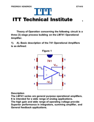
Figure 1
Description
The LM741 series are general purpose operational amplifiers.
It is intended for a wide range of analog applications.
The high gain and wide range of operating voltage provide
Superior performance in integrators, summing amplifier, and
General feedback applications.
2. FREDRICK KENDRICK ET1410
2
B). Maximum Voltage Level: +15
Minimum Voltage Lever: -15
C). Polarity Change… Positive flow 1800
to Negative flow
1800
. (Total 3600
)
It is necessary for an amplifier to be able to output true AC
voltage (polarity) to the load, a split DC power supply may be
used, whereby the ground point is electrically "centered"
between +V and -V. Sometimes the split power supply
configuration is referred to as a dual power supply.
4. FREDRICK KENDRICK ET1410
4
The amplifier is still being supplied with 30 volts overall,
but with the split voltage DC power supply; the output
voltage across the load resistor can now swing from a
theoretical maximum of +15 volts to -15 volts, instead of +30
volts to 0 volts. This is an easy way to get true alternating
current (AC) output from an amplifier without resorting to
capacitive or inductive (transformer) coupling on the output.
The peak-to-peak amplitude of this amplifier's output
between cutoff and saturation remains unchanged.
D). When the alternating flow of current change from
(Positive) 1800
in polarity to 1800
(Negative) polarity the
LED’s go through a switching from RED to YELLOW
indicating what type of current is active.
5. FREDRICK KENDRICK ET1410
5
Figure 3 (Final)
E). How to determine the time that the Capacitor will
take to exceed the reference voltage in figure3.
U2
UA741CP
3
2
4
7
6
51
LED1LED2
R1
1MΩ
R2
22kΩ
R3
27kΩ
R4
820Ω
C2
100µF
S1
Key = A
R5
50kΩ
Key=A
70%
V1
15 V
V2
15 V
XMM1
XMM2
6. FREDRICK KENDRICK ET1410
6
Figure 3 (Example)
Figure 3
When the output is saturated positive, the Vref will be
positive, and the capacitor will charge up in a positive
direction. When Vramp exceeds Vref by the tiniest margin, the
output will saturate negative, and the capacitor will charge in
the opposite direction (polarity). Oscillation occurs because
the positive feedback is instantaneous and the negative
feedback is delayed (by means of an RC time constant). The
7. FREDRICK KENDRICK ET1410
7
frequency of this oscillator may be adjusted by varying the
size of any component.
2). Calculations Table:
Circuit Calculations MultiSim
+15 +15 +14.676
-15 -15 -14.894
27.5 TO 28.9
SECONDS
28 SECONDS VARIED
DEFINITION
3). Parts added to Figure 7:
1 RED LED
1 YELLOW LED
1 100µf CAPACITOR
1 50kΩ / 70% POTENTIOMETER
1 820Ω RESISTOR
1 1.0 MEGΩ RESISTOR
1 22kΩ RESISTOR
1 27kΩ RESISTOR
8. FREDRICK KENDRICK ET1410
8
4). MultiSim Schematic Circuit Diagram added to Word
Document with needed modifications from figure #1 and
figure #2 to figure #3.
5). Project uploaded to e-portfolio via student portal.
Instructor will verify project:
INSTRUCTOR Don Heller
Electrical Engineering Department
ITT-Technical Institute
Indianapolis, Indiana. 46219