SlideShare a Scribd company logo
1 of 23
Download to read offline
ROBO Cylinder RCP2/RCA-SRA 
Short Length Type 
Sold & Serviced By: 
ELECTROMATE 
Toll Free Phone (877) SERVO98 
Toll Free Fax (877) SERV099 
www.electromate.com 
sales@electromate.com
We have reduced the length 
by a maximum of 45% 
compared to the existing model 
11 Significantly shortened length 
We have shortened the length of the 
actuator by up to 129mm compared to 
the current equivalent model. (*1) 
Customers can now use the actuator in 
narrow locations where there is very 
little space. 
(*1) Compared to RCA−RA3C 
50 
50 
50 
50 
 Length Comparison with Existing Model 
Compared to RCA-RA3C Compared to RCA-RA3R 
(   ) 
(   ) 
(   ) 
(   ) 
RCA-RA3C 
50 stroke 
RCA-SRA4R 
50 stroke 
RCA−RA3R 
50 stroke 
RCA−SRA4R 
50 stroke 
Shortened by 129mm Shortened by 63.5mm 
Select pulse force lowering type during A selected applied or required. a selected, single 3 installed. 
There surfaces We optional flanges (bottom, 1 
Sold  Serviced By: 
ELECTROMATE 
Toll Free Phone (877) SERVO98 
Toll Free Fax (877) SERV099 
www.electromate.com 
sales@electromate.com
Example of use 
Pulse motor: RCP2 Series 
Low-speed raising and lowering operations, 
Usage Usage 
Single guide 
Installed on left 
such as clamping and press fitting 
Single guide 
Installed on bottom 
Servo Motor: RCA Series 
Positioning during high-speed transfer 
Single guide 
Installed on right 
Double-guide 
Flange 
(Installed on front) 
Flange 
(Installed on rear) 
Foot bracket 
(Installed on bottom) 
Foot bracket 
(Installed on side) 
Used to raise and lower 
the stopper Used with a clamp 
22 Choose between a pulse motor or servo motor 
Select between 2 types of motors: a 
pulse motor type suitable for push 
force and low-speed raising and 
lowering operations, or a servo motor 
type effective for stable transportation 
during high-speed operations 
33 A guide type can be selected 
A guide type can be 
selected if a load is 
applied to the end of a rod, 
or if a straight motion is 
required. A single guide or 
a double guide can be 
selected, and for the 
single guide, there are 
3 directions that it can be 
installed. 
44 Flexible Installation method 
There are 5 installation 
surfaces on the actuator. 
We have also prepared 
optional front and rear 
flanges and foot brackets 
(bottom, side). 
2 
Sold  Serviced By: 
ELECTROMATE 
Toll Free Phone (877) SERVO98 
Toll Free Fax (877) SERV099 
www.electromate.com 
sales@electromate.com
Product  Specification List  Model description 
 Product  Specification List  Model description 
Maximum load capacity (*) 
I 35P P1 
Maximum load capacity (*) 
Series Type Encoder type Motor type Ball screw lead Stroke Compatible Controllers Cable length Option 
SRA4R 
SRGS4R 
SRGD4R 
I Incremental 
35P 35P pulse motor, 35 size 
5 5mm 
2.5 2.5mm 
PCON/RPCON 
PSEL 
B Brake (*) 
FL Flange bracket (front) 
FLR Flange bracket (rear) 
FT Foot bracket 
FT2 Foot bracket (Mounted on right) 
FT4 Foot bracket (Mounted on left) 
GS2 Single guide, mounted on right 
GS3 Single guide, mounted on bottom 
GS4 Single guide, mounted on left 
NM Reversed-home specification 
P1 
N No cable 
P 1m 
S 3m 
M 5m 
X Length Designation 
Series Name Motor type Type Stroke 
Ball screw 
lead Maximum speed Rated thrust Maximum 
Horizontal Vertical pushing force 
RCP2 
RCA 
Pulse motor 
35 
5 
2.5 
5 
2.5 
5 
2.5 
5 
2.5 
5 
2.5 
5 
2.5 
250 
125 
250 
125 
250 
125 
250 
125 
250 
125 
250 
125 
— 
— 
— 
— 
— 
— 
41 
81 
41 
81 
41 
81 
10 to 25 
30 to 35 
9 to 24 
30 to 35 
9 to 24 
30 to 35 
9 
18 
9 
18 
9 
18 
2 to 9 
3 to 15 
1 to 8 
3 to 15 
1 to 8 
3 to 15 
3 
6.5 
2 
5.5 
2 
5.5 
90 
170 
90 
170 
90 
170 
— 
— 
— 
— 
— 
— 
20 to 200mm 
20 to 100 are 
set every 10mm. 
100 to 200 are 
set every 50mm. 
Standard 
(no guide) 
With 
single guide 
With 
double guide 
Standard 
(no guide) 
With 
single guide 
With 
double guide 
Servo Motor 
20W 
Reversing Type 
Short Rod Type 
Reversing Type 
Short Rod Type 
with Single Guide 
Reversing Type 
Short Rod Type 
with Double Guide 
20 20mm 
to to 
200 200mm 
P1 
   20 to 100 are set every 10mm. 
100 to 200 are set every 50mm. 
*The brake specification can only be used with a 70mm or higher stroke. 
I 20 A 1 
I 20 A 1 
Series Type Encoder type Motor type Ball screw lead Stroke Compatible Controllers Cable length Option 
*The brake specification can only be used with a 70mm or higher stroke. 
SRA4R 
SRGS4R 
SRGD4R 
I Incremental 
20 Servo Motor 20W 
5 5mm 
2.5 2.5mm 
ACON/RACON 
A1 
  ASEL 
N No cable 
P 1m 
S 3m 
M 5m 
X Length Designation 
RCP2 
RCA 
Reversing Type 
Short Rod Type 
Reversing Type 
Short Rod Type 
with Single Guide 
Reversing Type 
Short Rod Type 
with Double Guide 
B Brake (*) 
FL Flange bracket (front) 
FLR Flange bracket (rear) 
FT Foot bracket 
FT2 Foot bracket (Mounted on right) 
FT4 Foot bracket (Mounted on left) 
GS2 Single guide, mounted on right 
GS3 Single guide, mounted on bottom 
GS4 Single guide, mounted on left 
NM Reversed-home specification 
A1 
20 20mm 
to to 
200 200mm 
20 to 100 are set every 10mm. 
100 to 200 are set every 50mm. 
Pulse motor type 
Servo Motor Type 
I 35P P1 
Series Type Encoder type Motor type Ball screw lead Stroke Compatible Controllers Cable length Option 
SRA4R 
SRGS4R 
SRGD4R 
I Incremental 
35P 35P pulse motor, 35 size 
5 5mm 
2.5 2.5mm 
PCON/RPCON 
PSEL 
B Brake (*) 
FL Flange bracket (front) 
FLR Flange bracket (rear) 
FT Foot bracket 
FT2 Foot bracket (Mounted on right) 
FT4 Foot bracket (Mounted on left) 
GS2 Single guide, mounted on right 
GS3 Single guide, mounted on bottom 
GS4 Single guide, mounted on left 
NM Reversed-home specification 
N No cable 
P 1m 
S 3m 
M 5m 
X Length Designation 
Series Name Motor type Type Stroke 
Ball screw 
lead Maximum speed Rated thrust Maximum 
Horizontal Vertical pushing force 
RCP2 
RCA 
Pulse motor 
35 
5 
2.5 
5 
2.5 
5 
2.5 
5 
2.5 
5 
2.5 
5 
2.5 
250 
125 
250 
125 
250 
125 
250 
125 
250 
125 
250 
125 
— 
— 
— 
— 
— 
— 
41 
81 
41 
81 
41 
81 
10 to 25 
30 to 35 
9 to 24 
30 to 35 
9 to 24 
30 to 35 
9 
18 
9 
18 
9 
18 
2 to 9 
3 to 15 
1 to 8 
3 to 15 
1 to 8 
3 to 15 
3 
6.5 
2 
5.5 
2 
5.5 
90 
170 
90 
170 
90 
170 
— 
— 
— 
— 
— 
— 
20 to 200mm 
20 to 100 are 
set every 10mm. 
100 to 200 are 
set every 50mm. 
Standard 
(no guide) 
With 
single guide 
With 
double guide 
Standard 
(no guide) 
With 
single guide 
With 
double guide 
Servo Motor 
20W 
Reversing Type 
Short Rod Type 
Reversing Type 
Short Rod Type 
with Single Guide 
Reversing Type 
Short Rod Type 
with Double Guide 
20 20mm 
to to 
200 200mm 
20 to 100 are set every 10mm. 
100 to 200 are set every 50mm. 
*The brake specification can only be used with a 70mm or higher stroke. 
SRA4R 
SRGS4R 
SRGD4R 
I Incremental 
20 Servo Motor 20W 
5 5mm 
2.5 2.5mm 
ACON/RACON 
ASEL 
N No cable 
P 1m 
S 3m 
M 5m 
X Length Designation 
RCP2 
RCA 
Reversing Type 
Short Rod Type 
Reversing Type 
Short Rod Type 
with Single Guide 
Reversing Type 
Short Rod Type 
with Double Guide 
B Brake (*) 
FL Flange bracket (front) 
FLR Flange bracket (rear) 
FT Foot bracket 
FT2 Foot bracket (Mounted on right) 
FT4 Foot bracket (Mounted on left) 
GS2 Single guide, mounted on right 
GS3 Single guide, mounted on bottom 
GS4 Single guide, mounted on left 
NM Reversed-home specification 
20 20mm 
to to 
200 200mm 
20 to 100 are set every 10mm. 
100 to 200 are set every 50mm. 
Pulse motor type 
Servo Motor Type 
3 
Sold  Serviced By: 
ELECTROMATE 
Toll Free Phone (877) SERVO98 
Toll Free Fax (877) SERV099 
www.electromate.com 
sales@electromate.com
4 
PLC 
Actuator 
No. Ti t le Type 
I/O Cable 
Actuator 
Controller 
connector 
between cables 
Positioner Type 
Teaching Pendant 
Positioner Type 
PC software 
Program Type 
Teaching Pendant 
Program Type 
PC Software 
DC24V 
Power supply 
simple absolute 
unit 
Field Network 
DeviceNet 
CC-Link 
ProfiBus 
Teaching Pendant 
Model Remarks See page 
CB-PAC-PIO020 
CB-PACY-PIO020 
CB-PACPU-PIO020 
CB-PCS-MPA 
CB-ACS-MPA 
CON-T 
RCM-E 
RCM-P 
RCM-101-MW 
RCM-101-USB 
SEL-T-J 
SEL-TD-J 
IA-101-X-MW-J 
IA-101-X-USB 
PS-241 
PS-242 
PCON-ABU 
ACON-ABU 
for use with C/CG Type 
for use with CY Type 
for use with PL/PO type (pulse train) 
A motor/encoder integrated cable for use with RCP2 (PCON/RPCON/PSEL) 
A motor/encoder integrated cable for use with RCA (ACON/RACON/ASEL) 
Standard Teaching Pendant 
Simple Teaching Pendant 
Data Setting Unit 
RS232 Connection Type 
USB Connection Type 
Standard specification 
ANSI compatible specification 
RS232 Connection Type 
USB Connection Type 
100-V input 
200-V input 
for PCON 
for ACON 
(*) 
(*) 
(*) 
P19 
P19 
P22 
P22 
P22 
P22 
P22 
P22 
P22 
P22 
P22 
(*) 
(*) 
(*) 
(*) 
Cable length 2m 
(fitting for controller) 
for both PCON/ACON 
Cable lengths 1m/3m/5m 
(required option for actuator) 
Cable length 5m 
for PCON/ACON/ROBONET 
Auxillary cable for PC connection 
(5m) for PCON/ACON/ROBONET 
Cable length 5m 
for both PSEL/ASEL 
3 position enable switch 
for both PSEL/ASEL 
Auxillary cable for PC connection 
(5m) for both PSEL/ASEL 
1 
2 
3 
4 
5 
6 
7 
8 
9 
10 
1 2 3 
4 
5 
6 
7 
8 
9 
10 
Actuator 
Controller 
connector 
between 
cables 
Controllers 
(Positioner type) (Program Type) 
PCON/ACON 
C/CG type 
Teaching Pendant 
I/O Cable 
PC-compatible software simple absolute unit DC24VPower supply PC-compatible 
software 
PCON/ACON 
CY type 
PCON/ACON 
PL/PO type 
PCON/ACON 
SE type 
RPCON/RACON 
(ROBONET) 
PSEL 
ASEL 
 System Configuration 
(*)Refer to ROBO Cylinder General Catalog 2008. 
Sold  Serviced By: 
ELECTROMATE 
Toll Free Phone (877) SERVO98 
Toll Free Fax (877) SERV099 
www.electromate.com 
sales@electromate.com
RCP2 ROBO Cylinder 
RCP2-SRA4R ROBO Cylinder, Short Rod-Type, Actuator Diameter 45mm, 
n Model Description RCP2 SRA4R   I   35P              P1 
n Speed vs. Payload Graph 
Since the RCP2 Series uses a pulse motor, the 
payload decreases as speed increases. Use the 
table below to confirm that there is sufficient 
payload at the desired speed. 
5: 5mm 
2.5: 2.5mm 
O I N 
Actuator Specification Table 
nLeads and Payloads (Note 1) Note that the maximum load capacity decreases as the speed increases. nStroke and Maximum Speed 
5 RCP2-SRA4R 
Load capacity (kg) Load capacity (kg) 
40 
35 
30 
25 
40 
20 
35 
15 
30 
10 
25 
5 
20 
15 
10 
5 
0 
Horizontal 
Horizontal 
Lリeーadド 22..55 
Lリeーadド 22..55 
0 50 100 150 200 250 
Speed (mm/s) 
300 
20 
18 
16 
14 
12 
20 
10 
18 
8 
16 
6 
14 
4 
12 
2 
10 
8 
6 
4 
2 
0 
Lead 2.5 
Lead 2.5 
0 50 100 150 200 250 
Speed (mm/s) 
300 
Vertical 
Lead 5 
リード5 
リードLead 15 
9 
3 
Load capacity (kg) Load capacity (kg) 
0 
0 50 100 150 200 250 
Speed (mm/s) 
300 
0 
0 50 100 150 200 250 
Speed (mm/s) 
300 
Vertical 
Lead 5 
リード5 
リードLead 15 
9 
3 
Maximum payload (Note 1) Maximum pushing 
① Price List by Stroke ② Cable Length Price List 
③ Option Price List 
Pulse Motor, Motor Reversing Specification 
* See P3 for model descriptions. 
Legend Stroke Cable Length Option ③ ② ① (Unit = mm/s) 
(Note 2) Refer to the push force graph on P17. 
(Note 3) Every 50mm stroke at over 100mm. 
Stroke 
Lead 
20 to 200 
(every 10mm) 
250 
125 
5 
2.5 
Lead 
(mm) 
5 
2.5 
Horizontal (kg) 
25 
35 
Vertical (kg) 
force 
(N) (Note 2) 
Model 
9 
15 
90 
170 
Stroke 
(mm) 
RCP2-SRA4R-I-35P-5--P1-- ③ ② ① 
RCP2-SRA4R-I-35P-2.5--P1-- ③ ② ① 
20 to 200 
(every 10mm) 
(Note 3) 
Type Cable symbol 
Standard type 
*A built-in motor-encoder cable is standard, 
and meets the robot cable specification. 
*See P19 for maintenance cables. 
Type code 
*The brake can be used at 70 stroke or above. 
Special length 
P (1m) 
S (3m) 
M (5m) 
X06 (6m) – X10 (10m) 
X11 (11m) – X15 (15m) 
X16 (16m) – X20 (20m) 
Actuator Specification 
Item Descr ipt ion 
Ball screw φ8mm rolled C10 
±0.05mm 
0.1mm or less 
φ22mm 
− 
0 to 40°C, 85% RH or less (without condensation) 
5000km 
Drive System 
Positioning Repeatability 
Backlash 
Rod diameter 
Non-rotary Rod Precision 
Ambient operating temperature, humidity 
Service life 
Title Option code See page 
B 
FL 
FLR 
FT 
FT2/FT4 
− 
→P19 
→P19 
→P19 
→P19 
Brake 
Flange bracket (front) 
Flange bracket (rear) 
Foot bracket 1 (mounted on bottom) 
Foot brackets 2 (Mounted on right or left side) 
35P: Pulse motor 
35oSize 
I: Incremental 
specification 
P1: PCON 
RPCON 
PSEL 
N: None 
P: 1m 
S: 3m 
M: 5m 
Xoo: Length 
designation 
Options below 
See Pricing Table 
20:20mm 
to 
200:200mm 
(10mm pitch setting) 
*Every 50mm for strokes over 100mm. 
— 
— 
— 
— 
①Stroke 
(mm) 
SRA4R 
Encoder type 
Incremental 
20 to 50 
60 to 100 
150 
200 
Series  Type  Encoder type  Motor type  Lead  Stroke  Compatible Controllers   Cable length   Option 
(1) The RCP2 series uses a pulse motor so the load capacity decreases at high speeds. Confirm the 
payload at the desired speed in the Speed vs. Payload graph at right. 
(2) The payload is the value when operated at 0.3G acceleration (0.2G acceleration in vertical operation 
with lead 2.5). 
The above values are maximum acceleration. 
(3) The horizontal load capacity assumes use of an external guide.Take note that the interlock may get 
damaged if external force is applied from any direction other than the moving direction of the rod. 
P 
T 
Notes for 
selection 
Sold  Serviced By: 
ELECTROMATE 
Toll Free Phone (877) SERVO98 
Toll Free Fax (877) SERV099 
www.electromate.com 
sales@electromate.com
RCP2 ROBO Cylinder 
31.5 4.8 4.2 
Cable joint 
connector (*1) 
34 
E-M4, depth 10 
(Opposite side is same) 
B 22 
nDimensions and Weight by Stroke (If the unit has a brake, add 0.2kg) 
Stroke 20 30 40 50 60 70 80 90 100 150 200 
Compatible Controllers 
The RCP2 Series actuators can be operated with the following controllers. Select the type that is compatible with your application. 
4-M6, depth 12 
6 M10×1.25 
Title External View Features Maximum number of 
Model positioning points Input power Power-supply capacity See page 
PCON-CG-35PI-NP-2-0 
PCON-CY-35PI-NP-2-0 
PCON-PL-35PI-NP-2-0 
PCON-PO-35PI-NP-2-0 
PCON-SE-35PI-N-0-0 
RPCON-35P 
PSEL-C-1-35PI-NP-2-0 
Positioner 
Type 
Safety category 
compatible 
Positioner type 
Solenoid valve 
type 
Pulse series 
input type 
(Differential line 
driver specification) 
Pulse series 
input type 
(Open collector 
specification) 
Serial 
communication 
type 
Field 
network 
type(*1) 
Program 
control type 
Up to 512-point 
positioning 
possible 
(*1) In addition to the controller, the field network type also requires a Gateway unit (sold separately). 
512 points 
DC24V Maximum 2A 
Same as solenoid 
valve 
Controlled 
operation enabled 
3 points 
Differential line 
driver compatible 
Pulse series 
input type 
Open collector 
compatible 
Pulse series 
input type 
64 points 
768 points 
Serial 
communications 
Special Type 
Field Network 
Dedicated type 
(−) 
Programmed 
operation enabled 
Maximum biaxial 
operation enabled 
1500 points 
PCON-C-35PI-NP-2-0 
→P20 
(19.6) 
17 
34 
34 
㪤10×1.25 
㱢20 
㱢22 
㱢32 
22 7.5 (2D width area) 
4-M6, depth 12 
45 
95 
45 50 
34 
14 
14 
22.5 
(210) 
Secure at least 100 
E-M4, depth 10 
34 
24 C D×50 8 
ME SE Home ME( 2) 
34 
17 C D×50 15 
L 
A 
40.5 
3 
st 
3 
Dimensions of provided nut 
ST: stroke 
SE: stroke end 
ME: mechanical end 
Dimensions Drawing 
(*1) Connect the motor and encoder cable. See P19 for cable details. 
(*2) During home return, the slider moves to the mechanical end and then reverses. 
Pay attention to prevent contact between the slider and surrounding parts. 
* The brake specification does not effect the external dimensions. 
However, 70 is the minimum stroke for the brake specification. 
(The brake is not compatible at 60 strokes and under.) 
RCP2-SRA4R6 
L 
A 
B 
C 
D 
E 
Weight (kg) 
124.5 
84 
62 
30 
0 
4 
0.83 
134.5 
94 
72 
40 
0 
4 
0.89 
144.5 
104 
82 
50 
0 
4 
0.96 
154.5 
114 
92 
60 
0 
4 
1.02 
164.5 
124 
102 
70 
0 
4 
1.08 
174.5 
134 
112 
30 
1 
6 
1.14 
184.5 
144 
122 
40 
1 
6 
1.21 
194.5 
154 
132 
50 
1 
6 
1.27 
204.5 
164 
142 
60 
1 
6 
1.33 
254.5 
214 
192 
60 
2 
8 
1.64 
304.5 
264 
242 
60 
3 
10 
1.95 
Sold  Serviced By: 
ELECTROMATE 
Toll Free Phone (877) SERVO98 
Toll Free Fax (877) SERV099 
www.electromate.com 
sales@electromate.com
RCP2 ROBO Cylinder 
n Model Description RCP2 SRGS4R   I   35P              P1 
nSpeed vs. Payload Graph 
Since the RCP2 Series uses a pulse motor, the 
payload decreases as speed increases. Use the 
table below to confirm that there is sufficient 
payload at the desired speed. 
RCP2-SRGS4R 
5: 5mm 
2.5: 2.5mm 
(1) The RCP2 series uses a pulse motor so the load capacity decreases at high speeds. Confirm 
the payload at the desired speed in the Speed vs. Payload graph at right. 
(2) The payload is the value when operated at 0.3G acceleration (0.2G acceleration in vertical 
O I N 
Actuator Specification Table 
nLeads and Payloads (Note 1) Note that the maximum load capacity decreases as the speed increases. nStroke and Maximum Speed 
7 RCP2-SRGS4R 
40 
35 
30 
25 
40 
20 
35 
15 
30 
10 
25 
5 
20 
15 
10 
5 
0 
リード2.5 
24 
リード2.5 
24 
9 
9 
Horizontal 
Horizontal 
Speed (mm/s) 
0 50 100 150 200 250 300 
20 
18 
16 
14 
12 
20 
10 
18 
8 
16 
6 
14 
4 
12 
2 
10 
8 
6 
4 
2 
0 
Speed (mm/s) 
Vertical 
Vertical 
リード5 
3 
リード5 
リード2.5 
リード2.5 
15 
15 
1 
1 
3 
0 50 100 150 200 250 300 
Load capacity (kg) Load capacity (kg) 
Speed (mm/s) 
Lead 5 
Lead Lead 2.5 
Lead 2.5 
0 
0 50 100 150 200 250 300 
0 
0 50 100 150 200 250 300 
Load capacity (kg) Load capacity (kg) 
Speed (mm/s) 
Lead 5 
Lead Lead 2.5 
Lead 2.5 
Maximum payload (Note 1) Maximum pushing 
① Price List by Stroke ② Cable Length Price List 
③ Option Price List 
ROBO Cylinder, Rod-Type with Short Single Guide, Actuator Diameter 45mm, 
Servo Motor, Motor Reversing Specification 
* See P3 for model descriptions. 
Legend Stroke Cable Length Option ③ ② ① (Unit = mm/s) 
(Note 2) Refer to the push force graph on P17. 
(Note 3) Every 50mm stroke at over 100mm. 
operation with lead 2.5). 
The above values are maximum acceleration. 
(3) The horizontal load capacity assumes use of an external guide.See P.18 of the Technical 
Reference for the load capacities that can be used with the single guide that is provided. 
P 
T 
Notes for 
selection 
Stroke 
Lead 
20 to 200 
(every 10mm) 
250 
125 
5 
2.5 
Lead 
(mm) 
5 
2.5 
Horizontal (kg) 
24 
35 
Vertical (kg) 
force 
(N) (Note 2) 
Model 
8 
15 
90 
170 
Stroke 
(mm) 
RCP2-SRGS4R-I-35P-5--P1-- ③ ② ① 
RCP2-SRGS4R-I-35P-2.5--P1-- ③ ② ① 
20 to 200 
(every 10mm) 
(Note 3) 
Type Cable symbol 
Standard type 
*A built-in motor-encoder cable is standard, 
and meets the robot cable specification. 
*See P19 for maintenance cables. 
Type code 
*The brake can be used at 70 stroke or above. 
*Always input the direction the guide should be mounted on the model. 
*The guide and foot bracket cannot be used in the same direction. 
Special length 
P (1m) 
S (3m) 
M (5m) 
X06 (6m) – X10 (10m) 
X11 (11m) – X15 (15m) 
X16 (16m) – X20 (20m) 
Actuator Specification 
Item Descr ipt ion 
Ball screw φ8mm rolled C10 
±0.05mm 
0.1mm or less 
φ22mm 
±0.05 degrees 
0 to 40°C, 85% RH or less (without condensation) 
5000km 
Drive System 
Positioning Repeatability 
Backlash 
Rod diameter 
Non-rotary Rod Precision 
Ambient operating temperature, humidity 
Service life 
Title Option code See page 
B 
FLR 
FT 
FT2/FT4 
GS2 to GS4 
− 
→P19 
→P19 
→P19 
→P8 
Brake 
Flange bracket (rear) 
Foot bracket 1 (mounted on bottom) 
Foot brackets 2 (Mounted on right and left sides) 
Guide installation direction change 
— 
— 
— 
— 
①Stroke 
(mm) 
SRGS4 
Encoder type 
Incremental 
20 to 50 
60 to 100 
150 
200 
Series  Type  Encoder type  Motor type  Lead  Stroke  Compatible Controllers  Cable length   Option 
35P: Pulse motor 
35oSize 
I: Incremental 
specification 
P1: PCON 
RPCON 
PSEL 
N: None 
P: 1m 
S: 3m 
M: 5m 
Xoo: Length 
designation 
Options below 
See Pricing Table 
20:20mm 
to 
200:200mm 
(10mm pitch setting) 
*Every 50mm for strokes over 100mm. 
Sold  Serviced By: 
ELECTROMATE 
Toll Free Phone (877) SERVO98 
Toll Free Fax (877) SERV099 
www.electromate.com 
sales@electromate.com
RCP2 ROBO Cylinder 
st 3 (Amount the shaft moves from the ME position on the home side to the home position) 
st 
17 C D×50 15 
34.5 8 A 
24 C D×50 8 
Dimensions Drawing 
0.5 44 50.5 
nDimensions and Weight by Stroke (If the unit has a brake, add 0.2kg) 
Stroke 20 30 40 50 60 70 80 90 100 150 200 
Compatible Controllers 
The RCP2 Series actuators can be operated with the following controllers. Select the type that is compatible with your application. 
4-M6, depth 12 
ST: stroke 
SE: stroke end 
ME: mechanical end 
Title External View Features Maximum number of 
Model positioning points Input power Power-supply capacity See page 
PCON-CG-35PI-NP-2-0 
PCON-CY-35PI-NP-2-0 
PCON-PL-35PI-NP-2-0 
PCON-PO-35PI-NP-2-0 
PCON-SE-35PI-N-0-0 
RPCON-35P 
PSEL-C-1-35PI-NP-2-0 
Positioner 
Type 
Safety category 
compatible 
Positioner type 
Solenoid valve 
type 
Pulse series 
input type 
(Differential line 
driver specification) 
Pulse series 
input type 
(Open collector 
specification) 
Serial 
communication 
type 
Field 
network 
type(*1) 
Program 
control type 
Up to 512-point 
positioning 
possible 
(*1) In addition to the controller, the field network type also requires a Gateway unit (sold separately). 
512 points 
DC24V Maximum 2A 
Same as solenoid 
valve 
Controlled 
operation enabled 
3 points 
Differential line 
driver compatible 
Pulse series 
input type 
Open collector 
compatible 
Pulse series 
input type 
64 points 
768 points 
Serial 
communications 
Special Type 
Field Network 
Dedicated type 
(−) 
Programmed 
operation enabled 
Maximum biaxial 
operation enabled 
1500 points 
PCON-C-35PI-NP-2-0 
→P20 
34 
34 
ME SE Home ME䋨 2䋩 
5.5 
㱢10 
2.5 80 8 
20 45 15 
42.5 st+60 4 
3 5 (Amount shaft pulls out at the SE position) 
3 
E-M4, depth 10 
34 
6-M5, depth 12 
90.5 
45.5 45 
95 
20 
7.5 30 
22.5 
30 30 5 
E-M4, depth 10 
(Opposite side is same) 
20 14.5 
34 
L 
B 22 
Cable joint 
connector (*1) 
䋨210䋩 
㱢34 
Secure at least 100 
GS3 
Mounted 
on bottom 
GS4 
Mounted 
on left 
Actuator 
GS2 
Mounted 
on right 
(Visual A) 
Guide Mounting Direction (see Visual A) 
(*1) Connect the motor and encoder cable. See P19 for cable details. 
(*2) During home return, the slider moves to the mechanical end and then reverses. 
Pay attention to prevent contact between the slider and surrounding parts. 
* The brake specification does not effect the external dimensions. 
However, 70 is the minimum stroke for the brake specification. 
(The brake is not compatible at 60 strokes and under.) 
RCP2-SRGS4R 8 
L 
A 
B 
C 
D 
E 
Weight (kg) 
126.5 
84 
62 
30 
0 
4 
1.2 
136.5 
94 
72 
40 
0 
4 
1.27 
146.5 
104 
82 
50 
0 
4 
1.34 
156.5 
114 
92 
60 
0 
4 
1.41 
166.5 
124 
102 
70 
0 
4 
1.48 
176.5 
134 
112 
30 
1 
6 
1.54 
186.5 
144 
122 
40 
1 
6 
1.61 
196.5 
154 
132 
50 
1 
6 
1.68 
206.5 
164 
142 
60 
1 
6 
1.75 
256.5 
214 
192 
60 
2 
8 
2.09 
306.5 
264 
242 
60 
3 
10 
2.43 
Sold  Serviced By: 
ELECTROMATE 
Toll Free Phone (877) SERVO98 
Toll Free Fax (877) SERV099 
www.electromate.com 
sales@electromate.com
RCP2 ROBO Cylinder 
RCP2-SRGD4R 
n Model Description RCP2   SRGD4R  I  35P              P1 
Series   Type  Encoder type Motor type  Lead  Stroke   Compatible Controllers   Cable length   Option 
35P: Pulse motor 
35oSize 
O I N 
Actuator Specification Table 
nLeads and Payloads (Note 1) Note that the maximum load capacity decreases as the speed increases. nStroke and Maximum Speed 
Title 
Brake 
Foot bracket 1 (mounted on bottom) 
nSpeed vs. Payload Graph 
Since the RCP2 Series uses a pulse motor, the 
payload decreases as speed increases. Use the 
table below to confirm that there is sufficient 
payload at the desired speed. 
9 RCP2-SRGD4R 
40 
35 
30 
25 
40 
20 
35 
15 
30 
10 
25 
5 
20 
15 
10 
5 
0 
リード2.5 
24 
リード2.5 
24 
9 
9 
Horizontal 
Horizontal 
Speed (mm/s) 
0 50 100 150 200 250 300 
20 
18 
16 
14 
12 
20 
10 
18 
8 
16 
6 
14 
4 
12 
2 
10 
8 
6 
4 
2 
0 
Speed (mm/s) 
Vertical 
Vertical 
リード5 
3 
リード5 
リード2.5 
リード2.5 
15 
15 
1 
1 
3 
0 50 100 150 200 250 300 
Load capacity (kg) Load capacity (kg) 
Speed (mm/s) 
Lead 5 
Lead Lead 2.5 
Lead 2.5 
0 
0 50 100 150 200 250 300 
0 
0 50 100 150 200 250 300 
Load capacity (kg) Load capacity (kg) 
Speed (mm/s) 
Lead 5 
Lead Lead 2.5 
Lead 2.5 
Maximum payload (Note 1) Maximum pushing 
① Price List by Stroke ② Cable Length Price List 
③ Option Price List 
ROBO Cylinder, Rod-Type with Short Guide, Actuator Diameter 45mm, 
Servo Motor, Motor Reversing Specification 
* See P3 for model descriptions. 
Legend Stroke Cable Length Option ③ ② ① (Unit = mm/s) 
(Note 2) Refer to the push force graph on P17. 
(Note 3) Every 50mm stroke at over 100mm. 
Stroke 
Lead 
20 to 200 
(every 10mm) 
250 
125 
5 
2.5 
Lead 
(mm) 
5 
2.5 
Horizontal (kg) 
24 
35 
Vertical (kg) 
force 
(N) (Note 2) 
Model 
8 
15 
90 
170 
Stroke 
(mm) 
RCP2-SRGD4R-I-35P-5--P1-- ③ ② ① 
RCP2-SRGD4R-I-35P-2.5--P1-- ③ ② ① 
20 to 200 
(every 10mm) 
(Note 3) 
Type Cable symbol 
Standard type 
*A built-in motor-encoder cable is standard, 
and meets the robot cable specification. 
*See P19 for maintenance cables. 
Type code 
*The brake can be used at 70 stroke or above. 
*The foot bracket cannot be mounted on the side. 
Special length 
P (1m) 
S (3m) 
M (5m) 
X06 (6m) – X10 (10m) 
X11 (11m) – X15 (15m) 
X16 (16m) – X20 (20m) 
Actuator Specification 
Item Descr ipt ion 
Ball screw φ8mm rolled C10 
±0.05mm 
0.1mm or less 
φ22mm 
±0.05 degrees 
0 to 40°C, 85% RH or less (without condensation) 
5000km 
Drive System 
Positioning Repeatability 
Backlash 
Rod diameter 
Non-rotary Rod Precision 
Ambient operating temperature, humidity 
Service life 
Option code See page 
B 
FT 
− 
→P19 
I: Incremental 
specification 
P1: PCON 
RPCON 
PSEL 
N: None 
P: 1m 
S: 3m 
M: 5m 
Xoo: Length 
designation 
Options below 
See Pricing 
Table 
20:20mm 
to 
200:200mm 
(10mm pitch setting) 
5: 5mm 
2.5: 2.5mm 
— 
— 
— 
— 
①Stroke 
(mm) 
SRGD4R 
Encoder type 
Incremental 
20 to 50 
60 to 100 
150 
200 
*Every 50mm for strokes over 100mm. 
(1) The RCP2 series uses a pulse motor so the load capacity decreases at high speeds. Confirm the 
payload at the desired speed in the Speed vs. Payload graph at right. 
(2) The payload is the value when operated at 0.3G acceleration (0.2G acceleration in vertical operation 
with lead 2.5). 
The above values are maximum acceleration. 
(3) The horizontal load capacity assumes use of an external guide.See P.18 of the Technical Reference for 
the load capacities that can be used with the double guide that is provided. 
P 
T 
Notes for 
selection 
Sold  Serviced By: 
ELECTROMATE 
Toll Free Phone (877) SERVO98 
Toll Free Fax (877) SERV099 
www.electromate.com 
sales@electromate.com
RCP2 ROBO Cylinder 
17 C D×50 15 
20 14.5 
34.5 8 A 
34 
st 
0.5 44 50.5 
30 30 30 
105 
126 
nDimensions and Weight by Stroke (If the unit has a brake, add 0.2kg) 
Stroke 20 30 40 50 60 70 80 90 100 150 200 
Compatible Controllers 
The RCP2 Series actuators can be operated with the following controllers. Select the type that is compatible with your application. 
ST: stroke 
SE: stroke end 
ME: mechanical end 
Title External View Features Maximum number of 
Model positioning points Input power Power-supply capacity See page 
PCON-CG-35PI-NP-2-0 
PCON-CY-35PI-NP-2-0 
PCON-PL-35PI-NP-2-0 
PCON-PO-35PI-NP-2-0 
PCON-SE-35PI-N-0-0 
RPCON-35P 
PSEL-C-1-35PI-NP-2-0 
Positioner Type 
Safety category 
compatible 
Positioner type 
Solenoid valve 
type 
Pulse series 
input type 
(Differential line 
driver specification) 
Pulse series 
input type 
(Open collector 
specification) 
Serial 
communication 
type 
Field 
network 
type(*1) 
Program 
control type 
Up to 512-point 
positioning 
possible 
(*1) In addition to the controller, the field network type also requires a Gateway unit (sold separately). 
512 points 
DC24V Maximum 2A 
Same as solenoid 
valve 
Controlled 
operation enabled 
3 points 
Differential line 
driver compatible 
Pulse series 
input type 
Open collector 
compatible 
Pulse series 
input type 
64 points 
768 points 
Serial 
communications 
Special Type 
Field Network 
Dedicated type 
(−) 
Programmed 
operation enabled 
Maximum biaxial 
operation enabled 
1500 points 
PCON-C-35PI-NP-2-0 
→P20 
15.5 7.5 
8-M5, depth 12 
(for mounting work piece) 
34 
L 
B 22 
E-M4, depth 10 
24 C D×50 8 
ME SE Home ME䋨 2䋩 
㱢34 
5.5 
㱢10 
45 45 7.5 15.5 
42.5 st+60 4 
3 5 (Amount shaft pulls out at the SE position) st 3 (Amount the shaft moves from the ME position on the home side to the home position) 
3 
34 
4-M6, depth 12 
34 
4-M5 
(for mounting to main unit) 
95 
34 
7.5 30 
20 
45.5 45 45.5 
136 
E-M4, depth 10 
(Opposite side is same) 
Cable joint 
connector (*1) 
䋨210䋩 
Secure at least 100 
22.5 
Dimensions Drawing 
(*1) Connect the motor and encoder cable. See P19 for cable details. 
(*2) During home return, the slider moves to the mechanical end and then reverses. 
Pay attention to prevent contact between the slider and surrounding parts. 
* The brake specification does not effect the external dimensions. 
However, 70 is the minimum stroke for the brake specification. 
(The brake is not compatible at 60 strokes and under.) 
RCP2-SRGD4R 10 
L 
A 
B 
C 
D 
E 
Weight (kg) 
126.5 
84 
62 
30 
0 
4 
1.47 
136.5 
94 
72 
40 
0 
4 
1.55 
146.5 
104 
82 
50 
0 
4 
1.62 
156.5 
114 
92 
60 
0 
4 
1.7 
166.5 
124 
102 
70 
0 
4 
1.77 
176.5 
134 
112 
30 
1 
6 
1.84 
186.5 
144 
122 
40 
1 
6 
1.92 
196.5 
154 
132 
50 
1 
6 
1.99 
206.5 
164 
142 
60 
1 
6 
2.07 
256.5 
214 
192 
60 
2 
8 
2.44 
306.5 
264 
242 
60 
3 
10 
2.81 
Sold  Serviced By: 
ELECTROMATE 
Toll Free Phone (877) SERVO98 
Toll Free Fax (877) SERV099 
www.electromate.com 
sales@electromate.com
RCA ROBO Cylinder 
RCA-SRA4R 
n Model Description RCA SRA4R   I   20              A1 
Series  Type  Encoder type  Motor type  Lead  Stroke  Compatible Controllers  Cable length   Option 
5 : 5mm 
2.5 : 2.5mm 
O I N 
For low-power 
applications 
Actuator Specification Table 
nLeads and Payloads nStroke and Maximum Speed 
Stroke 
Lead 
5 
2.5 
Lead 
(mm) 
5 
(N) Model 
2.5 
Maximum payload (Note 1) Rated thrust 
Horizontal (kg) 
9 
18 
Vertical (kg) 
3 
6.5 
41 
81 
Stroke 
(mm) 
RCA-SRA4R-I-20-5--A1-- ③ ② ① 
RCA-SRA4R-I-20-2.5--A1-- ③ ② ① 
20 to 200 
(every 10mm) 
(Note 1) 
① Price List by Stroke ② Cable Length Price List 
③ Option Price List 
11RCA-SRA4R 
ROBO Cylinder, Short Rod-Type, Actuator Diameter 45mm, Servo Motor, 
Motor Reversing Specification 
* See P3 for model descriptions. 
20 to 200 
(every 10mm) 
250 
125 
Legend Stroke Cable Length Option ③ ② ① (Unit = mm/s) 
Type Cable symbol 
Standard type 
*A built-in motor-encoder cable is standard, 
and meets the robot cable specification. 
*See P19 for maintenance cables. 
Type code 
*The brake can be used at 70 stroke or above. 
Special length 
P (1m) 
S (3m) 
M (5m) 
X06 (6m) – X10 (10m) 
X11 (11m) – X15 (15m) 
X16 (16m) – X20 (20m) 
Actuator Specification 
Item Descr ipt ion 
Ball screw φ8mm rolled C10 
±0.05mm 
0.1mm or less 
φ22mm 
− 
0 to 40°C, 85% RH or less (without condensation) 
5000km 
Drive System 
Positioning Repeatability 
Backlash 
Rod diameter 
Non-rotary Rod Precision 
Ambient operating temperature, humidity 
Service life 
Title Option code See page 
B 
FL 
FLR 
FT 
FT2/FT4 
LA 
− 
→P19 
→P19 
→P19 
→P19 
− 
Brake 
Flange bracket (front) 
Flange bracket (rear) 
Foot bracket 1 (mounted on bottom) 
Foot brackets 2 (Mounted on right or left sides) 
for energy saving 
A1: ACON 
RACON 
ASEL 
— 
— 
— 
— 
①Stroke 
(mm) 
SRA4 
Encoder type 
Incremental 
20 to 50 
60 to 100 
150 
200 
P 
T 
Notes for 
selection 
(1) The payload capacity acceleration is 0.3G acceleration (0.2G 
acceleration in vertical operation with lead 2.5). The above value 
is the maximum acceleration. 
(2) There is horizontal load capacity when external guides are used. 
Take note that if external force is applied in any direction other 
than moving direction the rod, the interlock may get damaged. 
(Note 1) Every 50mm for strokes over 100mm. 
20: Servo motor 
20W 
I: Incremental 
specification 
N: None 
P: 1m 
S: 3m 
M: 5m 
Xoo: Length 
designation 
Options below 
See Pricing Table 
20:20mm 
to 
200:200mm 
(10mm pitch setting) 
*Every 50mm for strokes over 100mm. 
Sold  Serviced By: 
ELECTROMATE 
Toll Free Phone (877) SERVO98 
Toll Free Fax (877) SERV099 
www.electromate.com 
sales@electromate.com
RCA ROBO Cylinder 
4-M6, depth 12 
6 M10×1.25 
(19.6) 
17 
34 
34 
31.5 4.8 4.2 
㪤10×1.25 
㱢20 
㱢22 
㱢32 
22 7.5 (2D width area) 
Cable joint 
connector (*1) 
4-M6, depth 12 
34 
45 
95 
45 50 
34 
14 
14 
22.5 
(210) 
Secure at least 100 
E-M4, depth 10 
(Opposite side is same) 
E-M4, depth 10 
B 22 
34 
24 C D×50 8 
ME SE Home ME( 2) 
34 
17 C D×50 15 
L 
A 
40.5 
3 
st 
3 
Dimensions of provided nut 
ST: stroke 
SE: stroke end 
ME: mechanical end 
Dimensions Drawing 
(*1) Connect the motor and encoder cable. See P19 for cable details. 
(*2) During home return, the slider moves to the mechanical end and then reverses. 
Pay attention to prevent contact between the slider and surrounding parts. 
* The brake specification does not effect the external dimensions. 
However, 70 is the minimum stroke for the brake specification. 
(The brake is not compatible at 60 strokes and under.) 
nDimensions and Weight by Stroke (If the unit has a brake, add 0.2kg) 
Stroke 20 30 40 50 60 70 80 90 100 150 200 
See page 
RCA-SRA4R12 
L 
A 
B 
C 
D 
E 
Weight (kg) 
124.5 
84 
62 
30 
0 
4 
0.78 
134.5 
94 
72 
40 
0 
4 
0.84 
144.5 
104 
82 
50 
0 
4 
0.9 
154.5 
114 
92 
60 
0 
4 
0.96 
164.5 
124 
102 
70 
0 
4 
1.03 
174.5 
134 
112 
30 
1 
6 
1.09 
184.5 
144 
122 
40 
1 
6 
1.15 
194.5 
154 
132 
50 
1 
6 
1.21 
204.5 
164 
142 
60 
1 
6 
1.27 
254.5 
214 
192 
60 
2 
8 
1.59 
304.5 
264 
242 
60 
3 
10 
1.9 
Compatible Controllers 
RCA Series actuators can be operated with the following controllers.. Select the type that is compatible with your application. 
Title External View Features Maximum number of 
Model positioning points Input power Power-supply capacity 
ACON-CG-20I①-NP-2-0 
ACON-CY-20I①-NP-2-0 
ACON-PL-20①-NP-2-0 
ACON-PO-20I①-NP-2-0 
ACON-SE-20I①-N-0-0 
RACON-20① 
ASEL-C-1-20I①-NP-2-0 
Positioner 
Type 
Safety category 
compatible 
Positioner type 
Solenoid valve 
type 
Pulse series 
input type 
(Differential line 
driver specification) 
Pulse series 
input type 
(Open collector 
specification) 
Serial 
communication 
type 
Field network 
type (*1) 
Program 
control type 
Up to 512-point 
positioning 
possible 
512 points 
DC24V 
(Standard) 
Rated 1.3A 
Peak 4.4A 
(energy-saving) 
Rated 1.3A 
Peak 2.5A 
(*2) 
Same as solenoid 
valve 
Controlled 
operation enabled 
3 points 
Differential line 
driver compatible 
Pulse series 
input type 
Open collector 
compatible 
Pulse series 
input type 
64 points 
Serial 
communications 
Special Type 
(−) 
Field Network 
Dedicated type 
Programmed 
operation enabled 
Maximum biaxial 
operation enabled 
768 points 
1500 points 
ACON-C-20I①-NP-2-0 
→P20 
*ASEL is for uniaxial specification. 
(*2) is entered as the code (LA) when designating for low-power applications.  
(*1) In addition to the controller, the field network type also requires a Gateway unit (sold separately). 
Sold  Serviced By: 
ELECTROMATE 
Toll Free Phone (877) SERVO98 
Toll Free Fax (877) SERV099 
www.electromate.com 
sales@electromate.com
RCA ROBO Cylinder 
RCA-SRGS4R ROBO Cylinder, Rod-Type with Short Single Guide, Actuator Diameter 45mm, Servo 
n Model Description RCA SRGS4R   I   20              A1 
Series  Type  Encoder type  Motor type  Lead  Stroke  Compatible Controllers   Cable length   Option 
A1: ACON 
*Every 50mm for strokes over 100mm. 
O I N 
For low-power 
applications 
Actuator Specification Table 
nLeads and Payloads nStroke and Maximum Speed 
Stroke 
Lead 
5 
2.5 
Lead 
(mm) 
5 
(N) Model 
2.5 
Maximum payload (Note 1) Rated thrust 
Horizontal (kg) 
9 
18 
Vertical (kg) 
2 
5.5 
41 
81 
Stroke 
(mm) 
RCA-SRGS4R-I-20-5--A1-- ③ ② ① 
RCA-SRGS4R-I-20-2.5--A1-- ③ ② ① 
20 to 200 
(every 10mm) 
(Note 1) 
① Price List by Stroke ② Cable Length Price List 
①Stroke 
(mm) 
20 to 50 
60 to 100 
150 
200 
③ Option Price List 
13 RCA-SRGS4R 
Motor, Motor Reversing Specification 
* See P3 for model descriptions. 
20 to 200 
(every 10mm) 
250 
125 
Legend Stroke Cable Length Option ③ ② ① (Unit = mm/s) 
Type Cable symbol 
Standard type 
*A built-in motor-encoder cable is standard, 
and meets the robot cable specification. 
*See P19 for maintenance cables. 
Type code 
SRGS4R 
Encoder type 
Incremental 
— 
— 
— 
— 
*The brake can be used at 70 stroke or above. 
*Always input the direction the guide should be mounted on the model. 
*The guide and foot bracket cannot be used in the same direction. 
Special length 
P (1m) 
S (3m) 
M (5m) 
X06 (6m) – X10 (10m) 
X11 (11m) – X15 (15m) 
X16 (16m) – X20 (20m) 
Actuator Specification 
Item Descr ipt ion 
Ball screw φ8mm rolled C10 
±0.05mm 
0.1mm or less 
φ22mm 
±0.05 degrees 
0 to 40°C, 85% RH or less (without condensation) 
5000km 
Drive System 
Positioning Repeatability 
Backlash 
Rod diameter 
Non-rotary Rod Precision 
Ambient operating temperature, humidity 
Service life 
Title Option code See page 
B 
FLR 
FT 
FT2/FT4 
GS2 to GS4 
LA 
− 
→P19 
→P19 
→P19 
→P14 
− 
Brake 
Flange bracket (rear) 
Foot bracket 1 (mounted on bottom) 
Foot brackets 2 (Mounted on right and left sides) 
Guide mounting direction 
For low-power applications 
P 
T 
Notes for 
selection 
(1) The payload capacity acceleration is 0.3G acceleration (0.2G 
acceleration in vertical operation with lead 2.5). The above value 
is the maximum acceleration. 
(2) There is horizontal load capacity when external guides are used. 
See P.18 of the Technical Reference for the load capacities that 
can be used with the single guide that is provided. 
(Note 1) Every 50mm for strokes over 100mm. 
RACON 
ASEL 
20: Servo motor 
20W 
I: Incremental 
specification 
N: None 
P: 1m 
S: 3m 
M: 5m 
Xoo : Length 
designation 
Options below 
See Pricing Table 
20:20mm 
to 
200:200mm 
(10mm pitch setting) 
5 : 5mm 
2.5 : 2.5mm 
Sold  Serviced By: 
ELECTROMATE 
Toll Free Phone (877) SERVO98 
Toll Free Fax (877) SERV099 
www.electromate.com 
sales@electromate.com
RCA ROBO Cylinder 
st 3 (Amount the shaft moves from the ME position on the home side to the home position) 
4-M6, depth 12 
ST: stroke 
SE: stroke end 
ME: mechanical end 
34 
34 
ME SE Home ME䋨 2䋩 
5.5 
㱢10 
2.5 80 8 
20 45 15 
42.5 st+60 4 
st 
3 5 (Amount shaft pulls out at the SE position) 
3 
17 C D×50 15 
34.5 8 A 
E-M4, depth 10 
24 C D×50 8 
34 
6-M5, depth 12 
90.5 
45.5 45 
Dimensions Drawing 
0.5 44 50.5 
95 
20 
7.5 30 
22.5 
30 30 5 
E-M4, depth 10 
(Opposite side is same) 
20 14.5 
34 
L 
B 22 
Cable joint 
connector (*1) 
䋨210䋩 
㱢34 
Secure at least 100 
GS3 
Mounted 
on bottom 
GS4 
Mounted 
on left 
Actuator 
GS2 
Mounted 
on right 
(Visual A) 
Guide Mounting Direction (see Visual A) 
(*1) Connect the motor and encoder cable. See P19 for cable details. 
(*2) During home return, the slider moves to the mechanical end and then reverses. 
Pay attention to prevent contact between the slider and surrounding parts. 
* The brake specification does not effect the external dimensions. 
However, 70 is the minimum stroke for the brake specification. 
(The brake is not compatible at 60 strokes and under.) 
nDimensions and Weight by Stroke (If the unit has a brake, add 0.2kg) 
Stroke 20 30 40 50 60 70 80 90 100 150 200 
See page 
RCA-SRGS4R14 
L 
A 
B 
C 
D 
E 
Weight (kg) 
126.5 
84 
62 
30 
0 
4 
1.15 
136.5 
94 
72 
40 
0 
4 
1.21 
146.5 
104 
82 
50 
0 
4 
1.28 
156.5 
114 
92 
60 
0 
4 
1.35 
166.5 
124 
102 
70 
0 
4 
1.42 
176.5 
134 
112 
30 
1 
6 
1.49 
186.5 
144 
122 
40 
1 
6 
1.56 
196.5 
154 
132 
50 
1 
6 
1.62 
206.5 
164 
142 
60 
1 
6 
1.69 
256.5 
214 
192 
60 
2 
8 
2.03 
306.5 
264 
242 
60 
3 
10 
2.38 
Compatible Controllers 
RCA Series actuators can be operated with the following controllers.. Select the type that is compatible with your application. 
Title External View Features Maximum number of 
Model positioning points Input power Power-supply capacity 
ACON-CG-20I①-NP-2-0 
ACON-CY-20I①-NP-2-0 
ACON-PL-20I①-NP-2-0 
ACON-PO-20I①-NP-2-0 
ACON-SE-20I①-N-0-0 
RACON-20① 
ASEL-C-1-20I①-NP-2-0 
Positioner 
Type 
Safety category 
compatible 
Positioner type 
Solenoid valve 
type 
Pulse series 
input type 
(Differential line 
driver specification) 
Pulse series 
input type 
(Open collector 
specification) 
Serial 
communication 
type 
Field network 
type (*1) 
Program 
control type 
Up to 512-point 
positioning 
possible 
512 points 
DC24V 
(Standard) 
Rated 1.3A 
Peak 4.4A 
(energy-saving) 
Rated 1.3A 
Peak 2.5A 
(*2) 
Same as solenoid 
valve 
Controlled 
operation enabled 
3 points 
Differential line 
driver compatible 
Pulse series 
input type 
Open collector 
compatible 
Pulse series 
input type 
64 points 
Serial 
communications 
Special Type 
(−) 
Field Network 
Dedicated type 
Programmed 
operation enabled 
Maximum biaxial 
operation enabled 
768 points 
1500 points 
ACON-C-20I①-NP-2-0 
→P20 
*ASEL is for uniaxial specification. 
(*2) is entered as the code (LA) when designating for low-power applications.  
(*1) In addition to the controller, the field network type also requires a Gateway unit (sold separately). 
Sold  Serviced By: 
ELECTROMATE 
Toll Free Phone (877) SERVO98 
Toll Free Fax (877) SERV099 
www.electromate.com 
sales@electromate.com
RCA ROBO Cylinder 
Series  Type  Encoder type  Motor type  Lead  Stroke  Compatible Controllers   Cable length   Option 
For low-power 
applications 
RCA-SRGD4R 
n Model Description RCA SRGD4R   I   20              A1 
O I N 
A1: ACON 
RACON 
ASEL 
Actuator Specification Table 
nLeads and Payloads nStroke and Maximum Speed 
Stroke 
Lead 
5 
2.5 
Lead 
(mm) 
5 
(N) Model 
2.5 
Maximum payload (Note 1) Rated thrust 
Horizontal (kg) 
9 
18 
Vertical (kg) 
2 
5.5 
41 
81 
Stroke 
(mm) 
RCA-SRGD4R-I-20-5--A1-- ③ ② ① 
RCA-SRGD4R-I-20-2.5--A1-- ③ ② ① 
20 to 200 
(every 10mm) 
(Note 1) 
① Price List by Stroke ② Cable Length Price List 
③ Option Price List 
15 RCA-SRGD4R 
ROBO Cylinder, Rod-Type with Short Double Guide, Actuator Diameter 45mm, 
Servo Motor, Motor Reversing Specification 
* See P3 for model descriptions. 
20 to 200 
(every 10mm) 
250 
125 
Legend Stroke Cable Length Option ③ ② ① (Unit = mm/s) 
Type Cable symbol 
Standard type 
*A built-in motor-encoder cable is standard, 
and meets the robot cable specification. 
*See P19 for maintenance cables. 
Type code 
*The brake can be used at 70 stroke or above. 
*The foot bracket cannot be mounted on the side. 
Special length 
P (1m) 
S (3m) 
M (5m) 
X06 (6m) – X10 (10m) 
X11 (11m) – X15 (15m) 
X16 (16m) – X20 (20m) 
Actuator Specification 
Item Descr ipt ion 
Ball screw φ8mm rolled C10 
±0.05mm 
0.1mm or less 
φ22mm 
±0.05 degrees 
0 to 40°C, 85% RH or less (without condensation) 
5000km 
Drive System 
Positioning Repeatability 
Backlash 
Rod diameter 
Non-rotary Rod Precision 
Ambient operating temperature, humidity 
Service life 
Title Option code See page 
B 
FT 
− 
→P19 
Brake 
Foot bracket1(mounted on bottom) 
— 
— 
— 
— 
①Stroke 
(mm) 
SRGD4 
Encoder type 
Incremental 
20 to 50 
60 to 100 
150 
200 
P 
T 
Notes for 
selection 
(1) The payload capacity acceleration is 0.3G acceleration (0.2G 
acceleration in vertical operation with lead 2.5). The above value 
is the maximum acceleration. 
(2) There is horizontal load capacity when external guides are used. 
See P.18 of the Technical Reference for the load capacities that 
can be used with the double guide that is provided. 
(Note 1) Every 50mm for strokes over 100mm. 
20: Servo motor 
20W 
I: Incremental 
specification 
N: None 
P: 1m 
S: 3m 
M: 5m 
Xoo : Length 
designation 
Options below 
See Pricing Table 
20:20mm 
to 
200:200mm 
(10mm pitch setting) 
5 : 5mm 
2.5 : 2.5mm 
*Every 50mm for strokes over 100mm. 
Sold  Serviced By: 
ELECTROMATE 
Toll Free Phone (877) SERVO98 
Toll Free Fax (877) SERV099 
www.electromate.com 
sales@electromate.com
RCA ROBO Cylinder 
ST: stroke 
SE: stroke end 
ME: mechanical end 
15.5 7.5 
st 
20 
8-M5, depth 12 
(for mounting work piece) 
34 
17 C D×50 15 
20 14.5 
34.5 8 A 
L 
B 22 
E-M4, depth 10 
34 
24 C D×50 8 
ME SE Home ME䋨 2䋩 
㱢34 
5.5 
㱢10 
45 45 7.5 15.5 
42.5 st+60 4 
3 5 (Amount shaft pulls out at the SE position) st 3 (Amount the shaft moves from the ME position on the home side to the home position) 
3 
34 
4-M6, depth 12 
34 
4-M5 
(for mounting to main unit) 
0.5 44 50.5 
95 
34 
7.5 30 
45.5 45 45.5 
30 30 30 
105 
126 
136 
E-M4, depth 10 
(Opposite side is same) 
Cable joint 
connector (*1) 
䋨210䋩 
Secure at least 100 
22.5 
Dimensions Drawing 
(*1) Connect the motor and encoder cable. See P19 for cable details. 
(*2) During home return, the slider moves to the mechanical end and then reverses. 
Pay attention to prevent contact between the slider and surrounding parts. 
* The brake specification does not effect the external dimensions. 
However, 70 is the minimum stroke for the brake specification. 
(The brake is not compatible at 60 strokes and under.) 
nDimensions and Weight by Stroke (If the unit has a brake, add 0.2kg) 
Stroke 20 30 40 50 60 70 80 90 100 150 200 
See page 
RCA-SRGD4R 16 
L 
A 
B 
C 
D 
E 
Weight (kg) 
126.5 
84 
62 
30 
0 
4 
1.42 
136.5 
94 
72 
40 
0 
4 
1.49 
146.5 
104 
82 
50 
0 
4 
1.56 
156.5 
114 
92 
60 
0 
4 
1.64 
166.5 
124 
102 
70 
0 
4 
1.71 
176.5 
134 
112 
30 
1 
6 
1.79 
186.5 
144 
122 
40 
1 
6 
1.86 
196.5 
154 
132 
50 
1 
6 
1.94 
206.5 
164 
142 
60 
1 
6 
2.01 
256.5 
214 
192 
60 
2 
8 
2.38 
306.5 
264 
242 
60 
3 
10 
2.75 
Compatible Controllers 
RCA Series actuators can be operated with the following controllers. Select the type that is compatible with your application. 
Title External View Features Maximum number of 
Model positioning points Input power Power-supply capacity 
ACON-CG-20I①-NP-2-0 
ACON-CY-20I①-NP-2-0 
ACON-PL-20I①-NP-2-0 
ACON-PO-20I①-NP-2-0 
ACON-SE-20I①-N-0-0 
RACON-20① 
ASEL-C-1-20I①-NP-2-0 
Positioner 
Type 
Safety category 
compatible 
Positioner type 
Solenoid valve 
type 
Pulse series 
input type 
(Differential line 
driver specification) 
Pulse series 
input type 
(Open collector 
specification) 
Serial 
communication 
type 
Field network 
type (*1) 
Program 
control type 
Up to 512-point 
positioning 
possible 
512 points 
DC24V 
(Standard) 
Rated 1.3A 
Peak 4.4A 
(energy-saving) 
Rated 1.3A 
Peak 2.5A 
(*2) 
Same as solenoid 
valve 
Controlled 
operation enabled 
3 points 
Differential line 
driver compatible 
Pulse series 
input type 
Open collector 
compatible 
Pulse series 
input type 
64 points 
Serial 
communications 
Special Type 
(−) 
Field Network 
Dedicated type 
Programmed 
operation enabled 
Maximum biaxial 
operation enabled 
768 points 
1500 points 
ACON-C-20I①-NP-2-0 
→P20 
*ASEL is for uniaxial specification. 
(*2) is entered as the code (LA) when designating for low-power applications.  
(*1) In addition to the controller, the field network type also requires a Gateway unit (sold separately). 
Sold  Serviced By: 
ELECTROMATE 
Toll Free Phone (877) SERVO98 
Toll Free Fax (877) SERV099 
www.electromate.com 
sales@electromate.com
Technical Reference 
Diagram Showing Relationship Between Push Force  Current-Limiting 
The push force applied in push-motion operation can be changed freely by changing the current-limiting value in 
the controller. 
Use the graph below to check the required push force. 
200 
150 
100 
50 
Allowable Rotating Torque 
2.5 
2.0 
1.5 
1.0 
0.5 
17 
Caution for Use 
• The relationships of push force the and current-limiting value represent reference values and may 
differ slightly from actual values. 
• If the current-limiting value is less than 20%, the push force may fluctuate. Keep the current-limiting 
value to 20% or above. 
• The travel speed is fixed to 20 mm/s during push-motion operation. 
• For applications requiring the use of push operation, please use the RCP2. (Pulse Motor) 
䊥Le䊷ad䊄 22..55 
If rotating torque is to be applied, keep the torque within the range specified below. 
Take note that standard and single-guide types cannot receive rotating torque. 
Allowable Rotating Moment 
0.0 
0 20 40 60 80 100 120 140 160 180 200 
Stroke (mm) 
Allowable Rotating Moment (N·m) 
0 
0 10 20 30 40 50 60 70 
Current Limitations (Percentage %) 
Push Force (N) 
RCP2-SRA4R/SRGS4R/SRGD4R 
Drawing Showing Correlation Between 
Push Force  Current Limitations 
Lead 5 
Sold  Serviced By: 
ELECTROMATE 
Toll Free Phone (877) SERVO98 
Toll Free Fax (877) SERV099 
www.electromate.com 
sales@electromate.com
Technical Reference 
18 
Relationship Between Allowable Load at Tip  Traveling Life 
The greater the load at the guide tip, the shorter the 
traveling life becomes. 
Select an appropriate model by considering an optimal 
balance between load and life. 
Horizontal 
Single guide type Double guide type (vertical and horizontal) 
Relationship Between Load on the Tip and Service Life 
by Stroke Single Guide 
40 
35 
30 
25 
20 
15 
10 
5 
0 
10 100 1000 10000 
Service Life (km) 
Radial Load (N) 
20 
50 
100 
150 
200 
Relationship Between Load on the Tip and Service Life, 
by Stroke Double Guide 
Service Life (km) 
Radial Load (N) 
20 
50 
100 
150 
200 
50 
45 
40 
35 
30 
25 
20 
15 
10 
5 
0 
10 100 1000 10000 
Radial Load  Deflection at Tip 
Single guide type 
Double guide type (horizontal) 
0 5 10 15 20 25 30 35 40 45 50 
Home 
20st 
30st 
40st 
50st 
60st 
70st 
80st 
90st 
100st 
110st 
120st 
130st 
140st 
150st 
160st 
170st 
180st 
190st 
200st 
Radial Load  Deflection on the Tip, Single Guide 
2.0 
1.8 
1.6 
1.4 
1.2 
1.0 
0.8 
0.6 
0.4 
0.2 
0.0 
Deflection (mm) 
Load (N) 
Horizontal 
0 5 10 15 20 25 30 35 40 45 50 
Home 
20st 
30st 
40st 
50st 
60st 
70st 
80st 
90st 
100st 
110st 
120st 
130st 
140st 
150st 
160st 
170st 
180st 
190st 
200st 
Radial Load  Deflection on the Tip, Double Guide (Horizontal) 
1.2 
1.0 
0.8 
0.6 
0.4 
0.2 
0.0 
Deflection (mm) 
Load (N) 
Double guide type (vertical) 
Radial Load  Deflection on the Tip, Double Guide (Vertical) 
1.2 
1.0 
0.8 
0.6 
0.4 
0.2 
0.0 
0 5 10 15 20 25 30 35 40 40 50 
Load (N) 
Deflection (mm) 
Home 
20st 
30st 
40st 
50st 
60st 
70st 
80st 
90st 
10st 
11st 
12st 
13st 
14st 
15st 
16st 
17st 
18st 
19st 
200st 
F↓ 
F 
Vertical 
F 
The diagrams below show how the load applied at the tip of the guide correlates with the deflection that results. 
F↓ 
F 
Vertical 
F 
Sold  Serviced By: 
ELECTROMATE 
Toll Free Phone (877) SERVO98 
Toll Free Fax (877) SERV099 
www.electromate.com 
sales@electromate.com
RCP2/RCA-Compatible Controllers 
Actuator options (flange/foot brackets) 
Model Options [FL] 
Single Model, RCP2-FL-SRA4 
Model Options [FT] 
Single Model, RCP2-FT-SRA4 
10 95 
60 
75 
Maintenance parts (motor-encoder cable) 
Motor-encoder cable for RCP2 
Motor-encoder cable for RCA 
(10) 
19 
L 
Model Options [FLR] 
Single Model, RCP2-FL-SRA4 
4-φ6.6, through 4-φ6.6, through 
Model Options [FT2 (mounted on right side/FT4 
(mounted on left side)] 
Single Model, RCP2-FTS-SRA4 
(18) 
10 
0.25 44.5 
4-φ6.6, through 
5.25 34 
(Front view) (Front view) 
Controller side Actuator Side 
(15) 
(φ12) 
When flange bracket (rear) is mounted 
10 45 
A 
VMM 
/A 
B 
VMM 
/B 
10 60 
Black 
White 
Red 
Green 
Yellow 
Brown 
Pink (Red) 
Pink (Blue) 
White (Red) 
White (Blue) 
Orange (Red) 
Orange (Blue) 
Gray (Red) 
Gray (Blue) 
Orange (Blue consecutive) 
Gray (Red consecutive) 
Gray (Blue consecutive) 
Shield 
B1 
A2 
A1 
B3 
B2 
A3 
A1 
B1 
A2 
B2 
A3 
B3 
A4 
B4 
A5 
B5 
A6 
B6 
A7 
B7 
A8 
B8 
A9 
B9 
A10 
B10 
A11 
B11 
A 
VMM 
/A 
B 
VMM 
/B 
NC 
NC 
BK+ 
BK− 
LS+ 
LS− 
A+ 
A− 
B+ 
B− 
NC 
VPS 
VCC 
GND 
NC 
FG 
BK+ 
BK− 
LS+ 
LS− 
A+ 
A− 
B+ 
B− 
NC 
VPS 
VCC 
GND 
NC 
FG 
14 
13 
16 
15 
12 
11 
10 
9 
8 
7 
6 
5 
4 
1 
(18) 
(8) 
(20) 
(8) 
(5) 
(30) 
(23) 
Signal Pin No. (Wire color) Signal Pin No. 
Model CB-PCS-MPA□□□ 
*Enter the cable length (L) for □□□, up to a maximum compatible length of 20m. 
Example: 080=8m 
(Front view) 
L 
Controller side Actuator Side 
Signal Pin No. Pin No. Signal 
U 
V 
W 
(Wire color) 
Red 
Yellow 
Black 
Yellow (Red) 
Yellow (Blue) 
Pink (Red) 
Pink (Blue) 
White (Red) 
White (Blue) 
Orange (Red) 
Orange (Blue) 
Gray (Red) 
Gray (Blue) 
Orange (Red consecutive) 
Orange (Blue consecutive) 
Gray (Red consecutive) 
Gray (Blue consecutive) 
Shield 
1 
2 
3 
A1 
B1 
A2 
B2 
A3 
B3 
A4 
B4 
A5 
B5 
A6 
B6 
A7 
B7 
A8 
B8 
A9 
B9 
A10 
B10 
A11 
B11 
U 
V 
W 
NC 
NC 
NC 
BK+ 
BK− 
LS+ 
LS− 
A+ 
A− 
B+ 
B− 
Z+ 
Z− 
− 
/PS 
VCC 
GND 
NC 
FG 
BK+ 
BK− 
LS+ 
LS− 
A+ 
A− 
B+ 
B− 
Z+ 
Z− 
− 
/PS 
VCC 
GND 
NC 
FG 
16 
15 
18 
17 
14 
13 
12 
11 
10 
9 
8 
7 
6 
5 
1 
(Front view) 
(12) 
(18) 
(8) 
(12) 
(23) 
(8) 
(5) 
(30) 
(18) 
Model CB-ACS-MPA□□□ 
*Enter the cable length (L) for □□□, up to a maximum compatible length of 20m. 
Example: 080=8m 
st+10 
4-φ6.6, through 
71 
57 
20 
105 
st+10 
121 
107 
20 
55 
0.25 44.5 
5.25 34 
75 
(40.5) 
When flange bracket (front) is mounted 
When foot bracket (bottom) is mounted When foot bracket (side) is mounted 
Sold  Serviced By: 
ELECTROMATE 
Toll Free Phone (877) SERVO98 
Toll Free Fax (877) SERV099 
www.electromate.com 
sales@electromate.com
RCP2/RCA-Compatible Controllers 
absolute unit 
Not for use with simple 
absolute unit 
20 
Model List 
Model 
Model 
PCON/ACON 
Name 
Appearance 
Features 
C CG CY PL/PO SE 
RPCON 
RACON 
(ROBONET) 
PSEL/ASEL 
Positioner type Solenoid valve type 
Serial Communication 
Type Program Type 
Safety category 
compatible type 
Pulse in-line control 
type 
Field Network 
type 
Positioner can be 
positioned for up to 
512 points. 
Can be operated 
using the same control 
as an air cylinder. 
An in-line pulse 
can be used to control 
as desired 
Serial Communication 
Dedicated Controller 
(*1) 
Can be operated through 
DeviceNet 
CC-Link 
ProfiBus 
Programmable, Built-in 
Sequence Function 
. 
Safety category 
compatible specification 
(*1) A Gateway unit (sold separately) is required to use RPCON/RACON. 
PCON/ACON Controller 
PCON/ACON 0 
Type Motor/Encoder Type I/O Type I/O Cable Length Power supply Simple absolute unit 
NP NPN specification 
(standard) 
PN PNP specification 
N No I/O (SE type) 
DeviceNet connection 
DV specification 
CC-Link connection 
CC specification 
ProfiBus connection 
PR specification 
0 No cable (*) 
2 2m 
3 3m 
5 5m 
NP NPN specification 
(standard) 
PN PNP specification 
ABU For use with simple 
0 DC24V 
DeviceNet connection 
DV specification 
CC-Link connection 
CC specification 
ProfiBus connection 
PR specification 
0 DC24V 
0 No cable (*) 
2 2m 
3 3m 
5 5m 
ABU 
C Positioner type 
CG Safety Category 
Compatible Type 
CY Solenoid valve type 
PL Pulse in-line control type 
(differential receiver type) 
Pulse in-line control type 
(open collector type) 
PO 
SE Serial Communication Type 
ROBONET Controller 
35PI For RCP2-SRA4R/ 
RPCON/RACON 
PSEL/ASEL Controller 
1 
2 
-ais specification 
2-ais specification 
35PI For RCP2-SRA4R/ 
SRGS4R/SRGD4R 
35PIB Use with the brake specifi-cations 
in the above model 
20I For C-S4/ 
SS4/SD4 
20IB se with the brake specifi-cations 
in the above model 
35PI For RCP2-SRA4R/ 
SRGS4R/SRGD4R 
35PIB Use with the brake specifi-cations 
in the above model 
20I For RCA-SRA4R/ 
SRGS4R/SRGD4R 
20IB Use with the brake specifi-cations 
in the above model 
Motor type Simple absolute unit 
PSEL/ASEL C 0 
Number of axes 
for connection 
Motor/Encoder Type I/O Type I/O Cable Length Power supply 
(2-axis) 
Motor/Encoder Type 
(first axis) 
* A Gateway unit is required to connect a network when 
using the RPCON/RACON types. 
See the ROBONET catalog for details. 
*Information under “2-axis” 
is not required for a 1-axis 
specification. 
SRGS4R/SRGD4R 
For RCA-SRA4R/ 
20I SRGS4R/SRGD4R 
35P For RCP2-SRA4R/ 
SRGS4R/SRGD4R 
For RCA-SRA4R/ 
20 SRGS4R/SRGD4R 
(*) The PCON/ACON-SE and PCON/ACON-C(CG)-DV/CC/PR 
types have no I/O. 
(*) The network specification (DV/CC/PR) 
types have no I/O. 
The network specification (DV/CC/PR) is 
only compatible with the positioner type (C) 
and safety category compatible type (CG). 
For use with simple 
absolute unit 
Not for use with simple 
absolute unit 
Controllers for RCP2/RCA 
Sold  Serviced By: 
ELECTROMATE 
Toll Free Phone (877) SERVO98 
Toll Free Fax (877) SERV099 
www.electromate.com 
sales@electromate.com
RCP2/RCA-Compatible Controllers 
Specification Table 
Operation method 
Number of positions 
I/O connector 
Serial communications 
Command pulse input method 
Maximum input pulse frequency 
Position detection method 
Motor/Encoder cable 
Input power 
Power-supply 
capacity 
RCP2 (all models) 
SRA4R 
SRGS4R 
SRGD4R 
Rated 1.3A, max. 4.4A (standard specification) 
Rated 1.3A, max. 2.5A (low-power specification) 
RCA (*2) 
Dimensional Outline Drawing 
21 
Item Specification 
Controller type 
PCON/ACON 
C CG CY PL PO SE 
Maximum number of control axes 
Number of I/O 
Peripheral Device 
Cables for communicating 
Dielectric strength voltage 
Ambient operating temperature, 
Ambient operating humidity. 
Ingress Protection 
Mass 
1-axis 
RPCON/RACON 
(ROBONET) 
Up to 16-axis can be 
connected and operated. 
Field Network 
768 points 
− 
CB-PAC-PIO CB-PACY-PIO CB-PACPU-PIO CB-RCB-CTL002 
− Differential line driver Open collector 
200kpps 60kpps 
− − 
Incremental encoder 
CB-PCS-MPA (for PCON)/CB-ACS-MPA(for ACON)(Max. length 20m) 
DC24V±10% 
− 
− 
− 
Maximum 2A Max. 2A (*1) 
DC500V 1MΩ 
0 to 40°C 10 to 95% (free from condensation or corrosive gases) 
IP20 
Approx. 300g Approx. 130g Approx. 200g 
PSEL/ASEL 
2-axes 
Program 
1500 points 
34-pin connector 
24 input 
8 output 
RS232 
CB-DS-PIO 
Max. 5.5A 
DC500V 
10MΩ 
Approx. 450g 
Positioner type 
512 points 
40-pin connector 
16 input, 16 output 
Solenoid valve type Pulse series input type 
3 points − 
12-pin connector 14-pin connector 
4 input 
6 output 
4 input, 4 output 
RS485 
Serial Communication Type 
64 points 
− 
− 
(*1) During use, the following amount of power is required: 2A x the number of units used, plus the power consumed by the Gateway unit (approx. 0.6A). 
(*2) The following power capacity is required for RACON: ACON power capacity x number of units used, plus the power consumed by the Gateway unit (approx. 0.6A). 
(*3) The following power capacity is required for ASEL: ACON power capacity x number of control axes, plus the power for the control unit (1.2A). 
(*3) 
PCON-C/CG 
ACON-C/CG 
PCON-CY/PL/PO/SE 
ACON-CY/PL/PO/SE 
RPCON 
RACON 
PSEL 
ASEL 
35 
178.5 
170.5 
㱢5 
84 
68.1 
5 
120 
112 
35 
5 
㱢5 68.1 
䋨0.5䋩 34 
䋨10䋩 
5 100 
䋨160䋩 (50 from the center 
(69.3 from the DIN rail surface) 
73.3 
of the DIN rail) 
35.4 
*Can be mounted on the 
DIN rail (35mm) 
㱢5 
159 
151 
137 
5 
3 
43 
(80) 110 
Sold  Serviced By: 
ELECTROMATE 
Toll Free Phone (877) SERVO98 
Toll Free Fax (877) SERV099 
www.electromate.com 
sales@electromate.com
RCP2/RCA-Compatible Controllers 
Controller Options 
Teaching Pendant This is a teaching device that provides information on functions such as 
position input, running tests, and monitoring. 
RCM-P CON-T SEL-T-J SEL-TD-J 
22 
Item RCM-E 
 
× 
 
× 
× 
 
× 


× 
× 
× 
× 
× 
× 
× 
× 
× 
× 
 
× 
× 
× 
 
× 


− 
Approx. 400g 
− 
Approx. 360g Approx. 400g 
IP54 
Approx. 400g Approx. 400g 
Exterior dimensions 
Compatible controllers 
Position input 
Program input 
Actuator operation 
Display 
3 position enabling switch 
Compatible with the ANSI standard 
Compatible with the CE mark 
Compatible with the UL standard 
Cable length 
Ambient operating temperature, humidity 
Ingress Protection 
Mass 
PCON/ACON/RPCON/RACON PSEL/ASEL 
16 characters x 2 lines, LCD display 20 characters x 4 lines, LCD display 
5m 
0 to 40°C temperature, 85% RH or less 
PC-compatible software 
(Windows only) 
Feature A startup support software program offering program/position 
input function, test operation function, monitoring function, 
and more. The functions needed for debugging have been 
enhanced to help reduce the startup time. 
PC-compatible software for PCON/ACON/RPCON/RACON (for RS232 connection) 
RCM−101−USB (comes with external device communication cable + USB conversion adapter + USB cable) 
5m 0.2m 
Connector 
conversion cable: 
CB-SEL-SJ002 
PC software (CD) 
RS232C cable: 
CB-ST-E1MW050-EB 
Dummy plug 
1m 
DP-3 
PC software (CD) 
USB cable 
CB-SEL-USB010 
 Model 
 Configuration 
 Model 
 Configuration 
IA−101−X−MW−J (comes with RS232C cable + connector conversion cable) 
 Model 
 Configuration 
IA−101−X−USB (for USB cable) 
USB conversion adapter 
RCB-CV-USB 
1m 5m 
PC software (CD) 
USB cable 
CB-SEL-USB010 
 Model 
 Configuration 
RCM−101−MW (comes with external device communication cable + RS232 conversion unit) 
RS232 conversion adapter 
RCB-CV-MW 
0.3m 
5m 
External device 
communication cable 
CB-RCA-SIO050 
External device 
communication cable 
CB-RCA-SIO050 
PC software (CD) 
PC-compatible software for PCON/ACON/RPCON/RACON (for USB connection) 
PC-compatible software for PSEL/ASEL (for RS232 connection) 
PC-compatible software (for USB connection) 
Sold  Serviced By: 
ELECTROMATE 
Toll Free Phone (877) SERVO98 
Toll Free Fax (877) SERV099 
www.electromate.com 
sales@electromate.com

More Related Content

What's hot

Iai rcaw ra4_c_ra4d_ra4r_specsheet
Iai rcaw ra4_c_ra4d_ra4r_specsheetIai rcaw ra4_c_ra4d_ra4r_specsheet
Iai rcaw ra4_c_ra4d_ra4r_specsheetElectromate
 
Iai rcp2 w_ra4c_specsheet
Iai rcp2 w_ra4c_specsheetIai rcp2 w_ra4c_specsheet
Iai rcp2 w_ra4c_specsheetElectromate
 
Iai rcp2 ra3_c_specsheet
Iai rcp2 ra3_c_specsheetIai rcp2 ra3_c_specsheet
Iai rcp2 ra3_c_specsheetElectromate
 
Iai rcp3 ra2_ar_specsheet
Iai rcp3 ra2_ar_specsheetIai rcp3 ra2_ar_specsheet
Iai rcp3 ra2_ar_specsheetElectromate
 
Iai rcs2 sa5_r_specsheet
Iai rcs2 sa5_r_specsheetIai rcs2 sa5_r_specsheet
Iai rcs2 sa5_r_specsheetElectromate
 
Iai erc2 rgs7_c_specsheet
Iai erc2 rgs7_c_specsheetIai erc2 rgs7_c_specsheet
Iai erc2 rgs7_c_specsheetElectromate
 
Iai rcs2 sa4_c_specsheet
Iai rcs2 sa4_c_specsheetIai rcs2 sa4_c_specsheet
Iai rcs2 sa4_c_specsheetElectromate
 
Iai rca ra4_c_specsheet
Iai rca ra4_c_specsheetIai rca ra4_c_specsheet
Iai rca ra4_c_specsheetElectromate
 
Iai rcp2 sa5_c_specsheet
Iai rcp2 sa5_c_specsheetIai rcp2 sa5_c_specsheet
Iai rcp2 sa5_c_specsheetElectromate
 
Iai rca2 sa6_c_specsheet
Iai rca2 sa6_c_specsheetIai rca2 sa6_c_specsheet
Iai rca2 sa6_c_specsheetElectromate
 
Iai rca srgs4_r_specsheet
Iai rca srgs4_r_specsheetIai rca srgs4_r_specsheet
Iai rca srgs4_r_specsheetElectromate
 
Iai rcacr sa5_d_specsheet
Iai rcacr sa5_d_specsheetIai rcacr sa5_d_specsheet
Iai rcacr sa5_d_specsheetElectromate
 
Iai rcs2 sa7_r_specsheet
Iai rcs2 sa7_r_specsheetIai rcs2 sa7_r_specsheet
Iai rcs2 sa7_r_specsheetElectromate
 
Iai rcp2 w_ra6c_specsheet
Iai rcp2 w_ra6c_specsheetIai rcp2 w_ra6c_specsheet
Iai rcp2 w_ra6c_specsheetElectromate
 
Iai rca2 sa4_r_specsheet
Iai rca2 sa4_r_specsheetIai rca2 sa4_r_specsheet
Iai rca2 sa4_r_specsheetElectromate
 
Iai erc2 rgd6_c_specsheet
Iai erc2 rgd6_c_specsheetIai erc2 rgd6_c_specsheet
Iai erc2 rgd6_c_specsheetElectromate
 
Iai erc2 rgd7_c_specsheet
Iai erc2 rgd7_c_specsheetIai erc2 rgd7_c_specsheet
Iai erc2 rgd7_c_specsheetElectromate
 
Iai rcs2 sa5_c_specsheet
Iai rcs2 sa5_c_specsheetIai rcs2 sa5_c_specsheet
Iai rcs2 sa5_c_specsheetElectromate
 
Iai rca a4_r_specsheet
Iai rca a4_r_specsheetIai rca a4_r_specsheet
Iai rca a4_r_specsheetElectromate
 
Iai rca ra3_d_specsheet
Iai rca ra3_d_specsheetIai rca ra3_d_specsheet
Iai rca ra3_d_specsheetElectromate
 

What's hot (20)

Iai rcaw ra4_c_ra4d_ra4r_specsheet
Iai rcaw ra4_c_ra4d_ra4r_specsheetIai rcaw ra4_c_ra4d_ra4r_specsheet
Iai rcaw ra4_c_ra4d_ra4r_specsheet
 
Iai rcp2 w_ra4c_specsheet
Iai rcp2 w_ra4c_specsheetIai rcp2 w_ra4c_specsheet
Iai rcp2 w_ra4c_specsheet
 
Iai rcp2 ra3_c_specsheet
Iai rcp2 ra3_c_specsheetIai rcp2 ra3_c_specsheet
Iai rcp2 ra3_c_specsheet
 
Iai rcp3 ra2_ar_specsheet
Iai rcp3 ra2_ar_specsheetIai rcp3 ra2_ar_specsheet
Iai rcp3 ra2_ar_specsheet
 
Iai rcs2 sa5_r_specsheet
Iai rcs2 sa5_r_specsheetIai rcs2 sa5_r_specsheet
Iai rcs2 sa5_r_specsheet
 
Iai erc2 rgs7_c_specsheet
Iai erc2 rgs7_c_specsheetIai erc2 rgs7_c_specsheet
Iai erc2 rgs7_c_specsheet
 
Iai rcs2 sa4_c_specsheet
Iai rcs2 sa4_c_specsheetIai rcs2 sa4_c_specsheet
Iai rcs2 sa4_c_specsheet
 
Iai rca ra4_c_specsheet
Iai rca ra4_c_specsheetIai rca ra4_c_specsheet
Iai rca ra4_c_specsheet
 
Iai rcp2 sa5_c_specsheet
Iai rcp2 sa5_c_specsheetIai rcp2 sa5_c_specsheet
Iai rcp2 sa5_c_specsheet
 
Iai rca2 sa6_c_specsheet
Iai rca2 sa6_c_specsheetIai rca2 sa6_c_specsheet
Iai rca2 sa6_c_specsheet
 
Iai rca srgs4_r_specsheet
Iai rca srgs4_r_specsheetIai rca srgs4_r_specsheet
Iai rca srgs4_r_specsheet
 
Iai rcacr sa5_d_specsheet
Iai rcacr sa5_d_specsheetIai rcacr sa5_d_specsheet
Iai rcacr sa5_d_specsheet
 
Iai rcs2 sa7_r_specsheet
Iai rcs2 sa7_r_specsheetIai rcs2 sa7_r_specsheet
Iai rcs2 sa7_r_specsheet
 
Iai rcp2 w_ra6c_specsheet
Iai rcp2 w_ra6c_specsheetIai rcp2 w_ra6c_specsheet
Iai rcp2 w_ra6c_specsheet
 
Iai rca2 sa4_r_specsheet
Iai rca2 sa4_r_specsheetIai rca2 sa4_r_specsheet
Iai rca2 sa4_r_specsheet
 
Iai erc2 rgd6_c_specsheet
Iai erc2 rgd6_c_specsheetIai erc2 rgd6_c_specsheet
Iai erc2 rgd6_c_specsheet
 
Iai erc2 rgd7_c_specsheet
Iai erc2 rgd7_c_specsheetIai erc2 rgd7_c_specsheet
Iai erc2 rgd7_c_specsheet
 
Iai rcs2 sa5_c_specsheet
Iai rcs2 sa5_c_specsheetIai rcs2 sa5_c_specsheet
Iai rcs2 sa5_c_specsheet
 
Iai rca a4_r_specsheet
Iai rca a4_r_specsheetIai rca a4_r_specsheet
Iai rca a4_r_specsheet
 
Iai rca ra3_d_specsheet
Iai rca ra3_d_specsheetIai rca ra3_d_specsheet
Iai rca ra3_d_specsheet
 

Similar to Iai rcp2 rca_sra_specsheet

Iai rcp2 srgd4_r_specsheet
Iai rcp2 srgd4_r_specsheetIai rcp2 srgd4_r_specsheet
Iai rcp2 srgd4_r_specsheetElectromate
 
Iai rcp2 sra4_r_specsheet
Iai rcp2 sra4_r_specsheetIai rcp2 sra4_r_specsheet
Iai rcp2 sra4_r_specsheetElectromate
 
Iai rcp2 ra4_c_specsheet
Iai rcp2 ra4_c_specsheetIai rcp2 ra4_c_specsheet
Iai rcp2 ra4_c_specsheetElectromate
 
Iai rcp2 srgs4_r_specsheet
Iai rcp2 srgs4_r_specsheetIai rcp2 srgs4_r_specsheet
Iai rcp2 srgs4_r_specsheetElectromate
 
Iai rcp2 w_rcaw_rcsaw_specsheet
Iai rcp2 w_rcaw_rcsaw_specsheetIai rcp2 w_rcaw_rcsaw_specsheet
Iai rcp2 w_rcaw_rcsaw_specsheetElectromate
 
Iai rcs2 sa5_d_specsheet
Iai rcs2 sa5_d_specsheetIai rcs2 sa5_d_specsheet
Iai rcs2 sa5_d_specsheetElectromate
 
Iai rcp2 rgd4_c_specsheet
Iai rcp2 rgd4_c_specsheetIai rcp2 rgd4_c_specsheet
Iai rcp2 rgd4_c_specsheetElectromate
 
Iai rca sa5_d_specsheet
Iai rca sa5_d_specsheetIai rca sa5_d_specsheet
Iai rca sa5_d_specsheetElectromate
 
Iai erc2 ra7_c_specsheet
Iai erc2 ra7_c_specsheetIai erc2 ra7_c_specsheet
Iai erc2 ra7_c_specsheetElectromate
 
Iai rcp2 sa6_c_specsheet
Iai rcp2 sa6_c_specsheetIai rcp2 sa6_c_specsheet
Iai rcp2 sa6_c_specsheetElectromate
 
Iai rcp3 ra2_br_specsheet
Iai rcp3 ra2_br_specsheetIai rcp3 ra2_br_specsheet
Iai rcp3 ra2_br_specsheetElectromate
 
Iai rcs2 cr_sa5d_specsheet
Iai rcs2 cr_sa5d_specsheetIai rcs2 cr_sa5d_specsheet
Iai rcs2 cr_sa5d_specsheetElectromate
 
Iai rcp2 ra6_c_specsheet
Iai rcp2 ra6_c_specsheetIai rcp2 ra6_c_specsheet
Iai rcp2 ra6_c_specsheetElectromate
 
Iai 03 rc general_cj0203-2_a_p145-300_rod
Iai 03 rc general_cj0203-2_a_p145-300_rodIai 03 rc general_cj0203-2_a_p145-300_rod
Iai 03 rc general_cj0203-2_a_p145-300_rodElectromate
 
Iai rcp2 rgd3_c_specsheet
Iai rcp2 rgd3_c_specsheetIai rcp2 rgd3_c_specsheet
Iai rcp2 rgd3_c_specsheetElectromate
 
Iai rcp2 rgs6_c_specsheet
Iai rcp2 rgs6_c_specsheetIai rcp2 rgs6_c_specsheet
Iai rcp2 rgs6_c_specsheetElectromate
 
Iai rcp2 rgd6_c_specsheet
Iai rcp2 rgd6_c_specsheetIai rcp2 rgd6_c_specsheet
Iai rcp2 rgd6_c_specsheetElectromate
 
Iai erc2 ra6_c_specsheet
Iai erc2 ra6_c_specsheetIai erc2 ra6_c_specsheet
Iai erc2 ra6_c_specsheetElectromate
 
Iai rcp2 hs8_r_specsheet
Iai rcp2 hs8_r_specsheetIai rcp2 hs8_r_specsheet
Iai rcp2 hs8_r_specsheetElectromate
 
Iai rcp2 cr_sa5c_specsheet
Iai rcp2 cr_sa5c_specsheetIai rcp2 cr_sa5c_specsheet
Iai rcp2 cr_sa5c_specsheetElectromate
 

Similar to Iai rcp2 rca_sra_specsheet (20)

Iai rcp2 srgd4_r_specsheet
Iai rcp2 srgd4_r_specsheetIai rcp2 srgd4_r_specsheet
Iai rcp2 srgd4_r_specsheet
 
Iai rcp2 sra4_r_specsheet
Iai rcp2 sra4_r_specsheetIai rcp2 sra4_r_specsheet
Iai rcp2 sra4_r_specsheet
 
Iai rcp2 ra4_c_specsheet
Iai rcp2 ra4_c_specsheetIai rcp2 ra4_c_specsheet
Iai rcp2 ra4_c_specsheet
 
Iai rcp2 srgs4_r_specsheet
Iai rcp2 srgs4_r_specsheetIai rcp2 srgs4_r_specsheet
Iai rcp2 srgs4_r_specsheet
 
Iai rcp2 w_rcaw_rcsaw_specsheet
Iai rcp2 w_rcaw_rcsaw_specsheetIai rcp2 w_rcaw_rcsaw_specsheet
Iai rcp2 w_rcaw_rcsaw_specsheet
 
Iai rcs2 sa5_d_specsheet
Iai rcs2 sa5_d_specsheetIai rcs2 sa5_d_specsheet
Iai rcs2 sa5_d_specsheet
 
Iai rcp2 rgd4_c_specsheet
Iai rcp2 rgd4_c_specsheetIai rcp2 rgd4_c_specsheet
Iai rcp2 rgd4_c_specsheet
 
Iai rca sa5_d_specsheet
Iai rca sa5_d_specsheetIai rca sa5_d_specsheet
Iai rca sa5_d_specsheet
 
Iai erc2 ra7_c_specsheet
Iai erc2 ra7_c_specsheetIai erc2 ra7_c_specsheet
Iai erc2 ra7_c_specsheet
 
Iai rcp2 sa6_c_specsheet
Iai rcp2 sa6_c_specsheetIai rcp2 sa6_c_specsheet
Iai rcp2 sa6_c_specsheet
 
Iai rcp3 ra2_br_specsheet
Iai rcp3 ra2_br_specsheetIai rcp3 ra2_br_specsheet
Iai rcp3 ra2_br_specsheet
 
Iai rcs2 cr_sa5d_specsheet
Iai rcs2 cr_sa5d_specsheetIai rcs2 cr_sa5d_specsheet
Iai rcs2 cr_sa5d_specsheet
 
Iai rcp2 ra6_c_specsheet
Iai rcp2 ra6_c_specsheetIai rcp2 ra6_c_specsheet
Iai rcp2 ra6_c_specsheet
 
Iai 03 rc general_cj0203-2_a_p145-300_rod
Iai 03 rc general_cj0203-2_a_p145-300_rodIai 03 rc general_cj0203-2_a_p145-300_rod
Iai 03 rc general_cj0203-2_a_p145-300_rod
 
Iai rcp2 rgd3_c_specsheet
Iai rcp2 rgd3_c_specsheetIai rcp2 rgd3_c_specsheet
Iai rcp2 rgd3_c_specsheet
 
Iai rcp2 rgs6_c_specsheet
Iai rcp2 rgs6_c_specsheetIai rcp2 rgs6_c_specsheet
Iai rcp2 rgs6_c_specsheet
 
Iai rcp2 rgd6_c_specsheet
Iai rcp2 rgd6_c_specsheetIai rcp2 rgd6_c_specsheet
Iai rcp2 rgd6_c_specsheet
 
Iai erc2 ra6_c_specsheet
Iai erc2 ra6_c_specsheetIai erc2 ra6_c_specsheet
Iai erc2 ra6_c_specsheet
 
Iai rcp2 hs8_r_specsheet
Iai rcp2 hs8_r_specsheetIai rcp2 hs8_r_specsheet
Iai rcp2 hs8_r_specsheet
 
Iai rcp2 cr_sa5c_specsheet
Iai rcp2 cr_sa5c_specsheetIai rcp2 cr_sa5c_specsheet
Iai rcp2 cr_sa5c_specsheet
 

More from Electromate

Automated screw thread quality checking using SMAC LAR55 actuator new produc...
Automated screw thread quality checking using SMAC LAR55 actuator  new produc...Automated screw thread quality checking using SMAC LAR55 actuator  new produc...
Automated screw thread quality checking using SMAC LAR55 actuator new produc...Electromate
 
An overview of the various kinematic models in both parallel and serial robot...
An overview of the various kinematic models in both parallel and serial robot...An overview of the various kinematic models in both parallel and serial robot...
An overview of the various kinematic models in both parallel and serial robot...Electromate
 
Galil motion control robotic symposium presentation-linear motion from non-li...
Galil motion control robotic symposium presentation-linear motion from non-li...Galil motion control robotic symposium presentation-linear motion from non-li...
Galil motion control robotic symposium presentation-linear motion from non-li...Electromate
 
Advanced motion controls robotics symposium presentation-open standard tools ...
Advanced motion controls robotics symposium presentation-open standard tools ...Advanced motion controls robotics symposium presentation-open standard tools ...
Advanced motion controls robotics symposium presentation-open standard tools ...Electromate
 
Maxon motor ag robotic symposium presentation-impedance control overview and ...
Maxon motor ag robotic symposium presentation-impedance control overview and ...Maxon motor ag robotic symposium presentation-impedance control overview and ...
Maxon motor ag robotic symposium presentation-impedance control overview and ...Electromate
 
Kollmorgen robotic symposium presentation-motor design impacts on the optimiz...
Kollmorgen robotic symposium presentation-motor design impacts on the optimiz...Kollmorgen robotic symposium presentation-motor design impacts on the optimiz...
Kollmorgen robotic symposium presentation-motor design impacts on the optimiz...Electromate
 
Harmonic drive llc robotics symposium presentation-designing from the inside ...
Harmonic drive llc robotics symposium presentation-designing from the inside ...Harmonic drive llc robotics symposium presentation-designing from the inside ...
Harmonic drive llc robotics symposium presentation-designing from the inside ...Electromate
 
Thomson Linear Dual Shaft Rail 2DA Modular Specs
Thomson Linear Dual Shaft Rail 2DA Modular SpecsThomson Linear Dual Shaft Rail 2DA Modular Specs
Thomson Linear Dual Shaft Rail 2DA Modular SpecsElectromate
 
Thomson Linear 2DA QuickSlide System with Brake
Thomson Linear 2DA QuickSlide System with BrakeThomson Linear 2DA QuickSlide System with Brake
Thomson Linear 2DA QuickSlide System with BrakeElectromate
 
Thomson Linear RoundRail 2CA Web Universal Carriage Specs
Thomson Linear RoundRail 2CA Web Universal Carriage SpecsThomson Linear RoundRail 2CA Web Universal Carriage Specs
Thomson Linear RoundRail 2CA Web Universal Carriage SpecsElectromate
 
Thomson Linear RoundRail 1VC Double End Supported Specs
Thomson Linear RoundRail 1VC Double End Supported SpecsThomson Linear RoundRail 1VC Double End Supported Specs
Thomson Linear RoundRail 1VC Double End Supported SpecsElectromate
 
Thomson Linear RoundRail 2CA Web Flanged Carriage Specs
Thomson Linear RoundRail 2CA Web Flanged Carriage SpecsThomson Linear RoundRail 2CA Web Flanged Carriage Specs
Thomson Linear RoundRail 2CA Web Flanged Carriage SpecsElectromate
 
Thomson Linear RoundRail Twin Shaft Web 2CA
Thomson Linear RoundRail Twin Shaft Web 2CAThomson Linear RoundRail Twin Shaft Web 2CA
Thomson Linear RoundRail Twin Shaft Web 2CAElectromate
 
Thomson Linear RoundRail 1VC Double Unsupported Specs
Thomson Linear RoundRail 1VC Double Unsupported SpecsThomson Linear RoundRail 1VC Double Unsupported Specs
Thomson Linear RoundRail 1VC Double Unsupported SpecsElectromate
 
Thomson Linear WhisperTrak Actuators
Thomson Linear WhisperTrak ActuatorsThomson Linear WhisperTrak Actuators
Thomson Linear WhisperTrak ActuatorsElectromate
 
Thomson T-Series Profile Rail
Thomson T-Series Profile RailThomson T-Series Profile Rail
Thomson T-Series Profile RailElectromate
 
Thomson Linear RoundRail Accessories Collapsable Bellows Specs
Thomson Linear RoundRail Accessories Collapsable Bellows SpecsThomson Linear RoundRail Accessories Collapsable Bellows Specs
Thomson Linear RoundRail Accessories Collapsable Bellows SpecsElectromate
 
Thomson Linear Roundrail Dual Shaft Rail 2DA Specs
Thomson Linear Roundrail Dual Shaft Rail 2DA SpecsThomson Linear Roundrail Dual Shaft Rail 2DA Specs
Thomson Linear Roundrail Dual Shaft Rail 2DA SpecsElectromate
 
Thomson Linear RoundRail Continuous Support 1PC Specs
Thomson Linear RoundRail Continuous Support 1PC SpecsThomson Linear RoundRail Continuous Support 1PC Specs
Thomson Linear RoundRail Continuous Support 1PC SpecsElectromate
 
Thomson Linear RoundRail Continuous Support 1PB Specs
Thomson Linear RoundRail Continuous Support 1PB SpecsThomson Linear RoundRail Continuous Support 1PB Specs
Thomson Linear RoundRail Continuous Support 1PB SpecsElectromate
 

More from Electromate (20)

Automated screw thread quality checking using SMAC LAR55 actuator new produc...
Automated screw thread quality checking using SMAC LAR55 actuator  new produc...Automated screw thread quality checking using SMAC LAR55 actuator  new produc...
Automated screw thread quality checking using SMAC LAR55 actuator new produc...
 
An overview of the various kinematic models in both parallel and serial robot...
An overview of the various kinematic models in both parallel and serial robot...An overview of the various kinematic models in both parallel and serial robot...
An overview of the various kinematic models in both parallel and serial robot...
 
Galil motion control robotic symposium presentation-linear motion from non-li...
Galil motion control robotic symposium presentation-linear motion from non-li...Galil motion control robotic symposium presentation-linear motion from non-li...
Galil motion control robotic symposium presentation-linear motion from non-li...
 
Advanced motion controls robotics symposium presentation-open standard tools ...
Advanced motion controls robotics symposium presentation-open standard tools ...Advanced motion controls robotics symposium presentation-open standard tools ...
Advanced motion controls robotics symposium presentation-open standard tools ...
 
Maxon motor ag robotic symposium presentation-impedance control overview and ...
Maxon motor ag robotic symposium presentation-impedance control overview and ...Maxon motor ag robotic symposium presentation-impedance control overview and ...
Maxon motor ag robotic symposium presentation-impedance control overview and ...
 
Kollmorgen robotic symposium presentation-motor design impacts on the optimiz...
Kollmorgen robotic symposium presentation-motor design impacts on the optimiz...Kollmorgen robotic symposium presentation-motor design impacts on the optimiz...
Kollmorgen robotic symposium presentation-motor design impacts on the optimiz...
 
Harmonic drive llc robotics symposium presentation-designing from the inside ...
Harmonic drive llc robotics symposium presentation-designing from the inside ...Harmonic drive llc robotics symposium presentation-designing from the inside ...
Harmonic drive llc robotics symposium presentation-designing from the inside ...
 
Thomson Linear Dual Shaft Rail 2DA Modular Specs
Thomson Linear Dual Shaft Rail 2DA Modular SpecsThomson Linear Dual Shaft Rail 2DA Modular Specs
Thomson Linear Dual Shaft Rail 2DA Modular Specs
 
Thomson Linear 2DA QuickSlide System with Brake
Thomson Linear 2DA QuickSlide System with BrakeThomson Linear 2DA QuickSlide System with Brake
Thomson Linear 2DA QuickSlide System with Brake
 
Thomson Linear RoundRail 2CA Web Universal Carriage Specs
Thomson Linear RoundRail 2CA Web Universal Carriage SpecsThomson Linear RoundRail 2CA Web Universal Carriage Specs
Thomson Linear RoundRail 2CA Web Universal Carriage Specs
 
Thomson Linear RoundRail 1VC Double End Supported Specs
Thomson Linear RoundRail 1VC Double End Supported SpecsThomson Linear RoundRail 1VC Double End Supported Specs
Thomson Linear RoundRail 1VC Double End Supported Specs
 
Thomson Linear RoundRail 2CA Web Flanged Carriage Specs
Thomson Linear RoundRail 2CA Web Flanged Carriage SpecsThomson Linear RoundRail 2CA Web Flanged Carriage Specs
Thomson Linear RoundRail 2CA Web Flanged Carriage Specs
 
Thomson Linear RoundRail Twin Shaft Web 2CA
Thomson Linear RoundRail Twin Shaft Web 2CAThomson Linear RoundRail Twin Shaft Web 2CA
Thomson Linear RoundRail Twin Shaft Web 2CA
 
Thomson Linear RoundRail 1VC Double Unsupported Specs
Thomson Linear RoundRail 1VC Double Unsupported SpecsThomson Linear RoundRail 1VC Double Unsupported Specs
Thomson Linear RoundRail 1VC Double Unsupported Specs
 
Thomson Linear WhisperTrak Actuators
Thomson Linear WhisperTrak ActuatorsThomson Linear WhisperTrak Actuators
Thomson Linear WhisperTrak Actuators
 
Thomson T-Series Profile Rail
Thomson T-Series Profile RailThomson T-Series Profile Rail
Thomson T-Series Profile Rail
 
Thomson Linear RoundRail Accessories Collapsable Bellows Specs
Thomson Linear RoundRail Accessories Collapsable Bellows SpecsThomson Linear RoundRail Accessories Collapsable Bellows Specs
Thomson Linear RoundRail Accessories Collapsable Bellows Specs
 
Thomson Linear Roundrail Dual Shaft Rail 2DA Specs
Thomson Linear Roundrail Dual Shaft Rail 2DA SpecsThomson Linear Roundrail Dual Shaft Rail 2DA Specs
Thomson Linear Roundrail Dual Shaft Rail 2DA Specs
 
Thomson Linear RoundRail Continuous Support 1PC Specs
Thomson Linear RoundRail Continuous Support 1PC SpecsThomson Linear RoundRail Continuous Support 1PC Specs
Thomson Linear RoundRail Continuous Support 1PC Specs
 
Thomson Linear RoundRail Continuous Support 1PB Specs
Thomson Linear RoundRail Continuous Support 1PB SpecsThomson Linear RoundRail Continuous Support 1PB Specs
Thomson Linear RoundRail Continuous Support 1PB Specs
 

Recently uploaded

Apidays New York 2024 - Passkeys: Developing APIs to enable passwordless auth...
Apidays New York 2024 - Passkeys: Developing APIs to enable passwordless auth...Apidays New York 2024 - Passkeys: Developing APIs to enable passwordless auth...
Apidays New York 2024 - Passkeys: Developing APIs to enable passwordless auth...apidays
 
Six Myths about Ontologies: The Basics of Formal Ontology
Six Myths about Ontologies: The Basics of Formal OntologySix Myths about Ontologies: The Basics of Formal Ontology
Six Myths about Ontologies: The Basics of Formal Ontologyjohnbeverley2021
 
Navigating the Deluge_ Dubai Floods and the Resilience of Dubai International...
Navigating the Deluge_ Dubai Floods and the Resilience of Dubai International...Navigating the Deluge_ Dubai Floods and the Resilience of Dubai International...
Navigating the Deluge_ Dubai Floods and the Resilience of Dubai International...Orbitshub
 
MINDCTI Revenue Release Quarter One 2024
MINDCTI Revenue Release Quarter One 2024MINDCTI Revenue Release Quarter One 2024
MINDCTI Revenue Release Quarter One 2024MIND CTI
 
Repurposing LNG terminals for Hydrogen Ammonia: Feasibility and Cost Saving
Repurposing LNG terminals for Hydrogen Ammonia: Feasibility and Cost SavingRepurposing LNG terminals for Hydrogen Ammonia: Feasibility and Cost Saving
Repurposing LNG terminals for Hydrogen Ammonia: Feasibility and Cost SavingEdi Saputra
 
Strategies for Landing an Oracle DBA Job as a Fresher
Strategies for Landing an Oracle DBA Job as a FresherStrategies for Landing an Oracle DBA Job as a Fresher
Strategies for Landing an Oracle DBA Job as a FresherRemote DBA Services
 
EMPOWERMENT TECHNOLOGY GRADE 11 QUARTER 2 REVIEWER
EMPOWERMENT TECHNOLOGY GRADE 11 QUARTER 2 REVIEWEREMPOWERMENT TECHNOLOGY GRADE 11 QUARTER 2 REVIEWER
EMPOWERMENT TECHNOLOGY GRADE 11 QUARTER 2 REVIEWERMadyBayot
 
Apidays New York 2024 - The Good, the Bad and the Governed by David O'Neill, ...
Apidays New York 2024 - The Good, the Bad and the Governed by David O'Neill, ...Apidays New York 2024 - The Good, the Bad and the Governed by David O'Neill, ...
Apidays New York 2024 - The Good, the Bad and the Governed by David O'Neill, ...apidays
 
How to Troubleshoot Apps for the Modern Connected Worker
How to Troubleshoot Apps for the Modern Connected WorkerHow to Troubleshoot Apps for the Modern Connected Worker
How to Troubleshoot Apps for the Modern Connected WorkerThousandEyes
 
Mcleodganj Call Girls 🥰 8617370543 Service Offer VIP Hot Model
Mcleodganj Call Girls 🥰 8617370543 Service Offer VIP Hot ModelMcleodganj Call Girls 🥰 8617370543 Service Offer VIP Hot Model
Mcleodganj Call Girls 🥰 8617370543 Service Offer VIP Hot ModelDeepika Singh
 
Introduction to use of FHIR Documents in ABDM
Introduction to use of FHIR Documents in ABDMIntroduction to use of FHIR Documents in ABDM
Introduction to use of FHIR Documents in ABDMKumar Satyam
 
Apidays New York 2024 - Scaling API-first by Ian Reasor and Radu Cotescu, Adobe
Apidays New York 2024 - Scaling API-first by Ian Reasor and Radu Cotescu, AdobeApidays New York 2024 - Scaling API-first by Ian Reasor and Radu Cotescu, Adobe
Apidays New York 2024 - Scaling API-first by Ian Reasor and Radu Cotescu, Adobeapidays
 
Modular Monolith - a Practical Alternative to Microservices @ Devoxx UK 2024
Modular Monolith - a Practical Alternative to Microservices @ Devoxx UK 2024Modular Monolith - a Practical Alternative to Microservices @ Devoxx UK 2024
Modular Monolith - a Practical Alternative to Microservices @ Devoxx UK 2024Victor Rentea
 
TrustArc Webinar - Unlock the Power of AI-Driven Data Discovery
TrustArc Webinar - Unlock the Power of AI-Driven Data DiscoveryTrustArc Webinar - Unlock the Power of AI-Driven Data Discovery
TrustArc Webinar - Unlock the Power of AI-Driven Data DiscoveryTrustArc
 
Finding Java's Hidden Performance Traps @ DevoxxUK 2024
Finding Java's Hidden Performance Traps @ DevoxxUK 2024Finding Java's Hidden Performance Traps @ DevoxxUK 2024
Finding Java's Hidden Performance Traps @ DevoxxUK 2024Victor Rentea
 
Platformless Horizons for Digital Adaptability
Platformless Horizons for Digital AdaptabilityPlatformless Horizons for Digital Adaptability
Platformless Horizons for Digital AdaptabilityWSO2
 
WSO2's API Vision: Unifying Control, Empowering Developers
WSO2's API Vision: Unifying Control, Empowering DevelopersWSO2's API Vision: Unifying Control, Empowering Developers
WSO2's API Vision: Unifying Control, Empowering DevelopersWSO2
 
Artificial Intelligence Chap.5 : Uncertainty
Artificial Intelligence Chap.5 : UncertaintyArtificial Intelligence Chap.5 : Uncertainty
Artificial Intelligence Chap.5 : UncertaintyKhushali Kathiriya
 
Polkadot JAM Slides - Token2049 - By Dr. Gavin Wood
Polkadot JAM Slides - Token2049 - By Dr. Gavin WoodPolkadot JAM Slides - Token2049 - By Dr. Gavin Wood
Polkadot JAM Slides - Token2049 - By Dr. Gavin WoodJuan lago vázquez
 
Vector Search -An Introduction in Oracle Database 23ai.pptx
Vector Search -An Introduction in Oracle Database 23ai.pptxVector Search -An Introduction in Oracle Database 23ai.pptx
Vector Search -An Introduction in Oracle Database 23ai.pptxRemote DBA Services
 

Recently uploaded (20)

Apidays New York 2024 - Passkeys: Developing APIs to enable passwordless auth...
Apidays New York 2024 - Passkeys: Developing APIs to enable passwordless auth...Apidays New York 2024 - Passkeys: Developing APIs to enable passwordless auth...
Apidays New York 2024 - Passkeys: Developing APIs to enable passwordless auth...
 
Six Myths about Ontologies: The Basics of Formal Ontology
Six Myths about Ontologies: The Basics of Formal OntologySix Myths about Ontologies: The Basics of Formal Ontology
Six Myths about Ontologies: The Basics of Formal Ontology
 
Navigating the Deluge_ Dubai Floods and the Resilience of Dubai International...
Navigating the Deluge_ Dubai Floods and the Resilience of Dubai International...Navigating the Deluge_ Dubai Floods and the Resilience of Dubai International...
Navigating the Deluge_ Dubai Floods and the Resilience of Dubai International...
 
MINDCTI Revenue Release Quarter One 2024
MINDCTI Revenue Release Quarter One 2024MINDCTI Revenue Release Quarter One 2024
MINDCTI Revenue Release Quarter One 2024
 
Repurposing LNG terminals for Hydrogen Ammonia: Feasibility and Cost Saving
Repurposing LNG terminals for Hydrogen Ammonia: Feasibility and Cost SavingRepurposing LNG terminals for Hydrogen Ammonia: Feasibility and Cost Saving
Repurposing LNG terminals for Hydrogen Ammonia: Feasibility and Cost Saving
 
Strategies for Landing an Oracle DBA Job as a Fresher
Strategies for Landing an Oracle DBA Job as a FresherStrategies for Landing an Oracle DBA Job as a Fresher
Strategies for Landing an Oracle DBA Job as a Fresher
 
EMPOWERMENT TECHNOLOGY GRADE 11 QUARTER 2 REVIEWER
EMPOWERMENT TECHNOLOGY GRADE 11 QUARTER 2 REVIEWEREMPOWERMENT TECHNOLOGY GRADE 11 QUARTER 2 REVIEWER
EMPOWERMENT TECHNOLOGY GRADE 11 QUARTER 2 REVIEWER
 
Apidays New York 2024 - The Good, the Bad and the Governed by David O'Neill, ...
Apidays New York 2024 - The Good, the Bad and the Governed by David O'Neill, ...Apidays New York 2024 - The Good, the Bad and the Governed by David O'Neill, ...
Apidays New York 2024 - The Good, the Bad and the Governed by David O'Neill, ...
 
How to Troubleshoot Apps for the Modern Connected Worker
How to Troubleshoot Apps for the Modern Connected WorkerHow to Troubleshoot Apps for the Modern Connected Worker
How to Troubleshoot Apps for the Modern Connected Worker
 
Mcleodganj Call Girls 🥰 8617370543 Service Offer VIP Hot Model
Mcleodganj Call Girls 🥰 8617370543 Service Offer VIP Hot ModelMcleodganj Call Girls 🥰 8617370543 Service Offer VIP Hot Model
Mcleodganj Call Girls 🥰 8617370543 Service Offer VIP Hot Model
 
Introduction to use of FHIR Documents in ABDM
Introduction to use of FHIR Documents in ABDMIntroduction to use of FHIR Documents in ABDM
Introduction to use of FHIR Documents in ABDM
 
Apidays New York 2024 - Scaling API-first by Ian Reasor and Radu Cotescu, Adobe
Apidays New York 2024 - Scaling API-first by Ian Reasor and Radu Cotescu, AdobeApidays New York 2024 - Scaling API-first by Ian Reasor and Radu Cotescu, Adobe
Apidays New York 2024 - Scaling API-first by Ian Reasor and Radu Cotescu, Adobe
 
Modular Monolith - a Practical Alternative to Microservices @ Devoxx UK 2024
Modular Monolith - a Practical Alternative to Microservices @ Devoxx UK 2024Modular Monolith - a Practical Alternative to Microservices @ Devoxx UK 2024
Modular Monolith - a Practical Alternative to Microservices @ Devoxx UK 2024
 
TrustArc Webinar - Unlock the Power of AI-Driven Data Discovery
TrustArc Webinar - Unlock the Power of AI-Driven Data DiscoveryTrustArc Webinar - Unlock the Power of AI-Driven Data Discovery
TrustArc Webinar - Unlock the Power of AI-Driven Data Discovery
 
Finding Java's Hidden Performance Traps @ DevoxxUK 2024
Finding Java's Hidden Performance Traps @ DevoxxUK 2024Finding Java's Hidden Performance Traps @ DevoxxUK 2024
Finding Java's Hidden Performance Traps @ DevoxxUK 2024
 
Platformless Horizons for Digital Adaptability
Platformless Horizons for Digital AdaptabilityPlatformless Horizons for Digital Adaptability
Platformless Horizons for Digital Adaptability
 
WSO2's API Vision: Unifying Control, Empowering Developers
WSO2's API Vision: Unifying Control, Empowering DevelopersWSO2's API Vision: Unifying Control, Empowering Developers
WSO2's API Vision: Unifying Control, Empowering Developers
 
Artificial Intelligence Chap.5 : Uncertainty
Artificial Intelligence Chap.5 : UncertaintyArtificial Intelligence Chap.5 : Uncertainty
Artificial Intelligence Chap.5 : Uncertainty
 
Polkadot JAM Slides - Token2049 - By Dr. Gavin Wood
Polkadot JAM Slides - Token2049 - By Dr. Gavin WoodPolkadot JAM Slides - Token2049 - By Dr. Gavin Wood
Polkadot JAM Slides - Token2049 - By Dr. Gavin Wood
 
Vector Search -An Introduction in Oracle Database 23ai.pptx
Vector Search -An Introduction in Oracle Database 23ai.pptxVector Search -An Introduction in Oracle Database 23ai.pptx
Vector Search -An Introduction in Oracle Database 23ai.pptx
 

Iai rcp2 rca_sra_specsheet

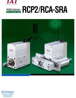
  • 1. ROBO Cylinder RCP2/RCA-SRA Short Length Type Sold & Serviced By: ELECTROMATE Toll Free Phone (877) SERVO98 Toll Free Fax (877) SERV099 www.electromate.com sales@electromate.com
  • 2. We have reduced the length by a maximum of 45% compared to the existing model 11 Significantly shortened length We have shortened the length of the actuator by up to 129mm compared to the current equivalent model. (*1) Customers can now use the actuator in narrow locations where there is very little space. (*1) Compared to RCA−RA3C 50 50 50 50 Length Comparison with Existing Model Compared to RCA-RA3C Compared to RCA-RA3R (   ) (   ) (   ) (   ) RCA-RA3C 50 stroke RCA-SRA4R 50 stroke RCA−RA3R 50 stroke RCA−SRA4R 50 stroke Shortened by 129mm Shortened by 63.5mm Select pulse force lowering type during A selected applied or required. a selected, single 3 installed. There surfaces We optional flanges (bottom, 1 Sold Serviced By: ELECTROMATE Toll Free Phone (877) SERVO98 Toll Free Fax (877) SERV099 www.electromate.com sales@electromate.com
  • 3. Example of use Pulse motor: RCP2 Series Low-speed raising and lowering operations, Usage Usage Single guide Installed on left such as clamping and press fitting Single guide Installed on bottom Servo Motor: RCA Series Positioning during high-speed transfer Single guide Installed on right Double-guide Flange (Installed on front) Flange (Installed on rear) Foot bracket (Installed on bottom) Foot bracket (Installed on side) Used to raise and lower the stopper Used with a clamp 22 Choose between a pulse motor or servo motor Select between 2 types of motors: a pulse motor type suitable for push force and low-speed raising and lowering operations, or a servo motor type effective for stable transportation during high-speed operations 33 A guide type can be selected A guide type can be selected if a load is applied to the end of a rod, or if a straight motion is required. A single guide or a double guide can be selected, and for the single guide, there are 3 directions that it can be installed. 44 Flexible Installation method There are 5 installation surfaces on the actuator. We have also prepared optional front and rear flanges and foot brackets (bottom, side). 2 Sold Serviced By: ELECTROMATE Toll Free Phone (877) SERVO98 Toll Free Fax (877) SERV099 www.electromate.com sales@electromate.com
  • 4. Product Specification List Model description Product Specification List Model description Maximum load capacity (*) I 35P P1 Maximum load capacity (*) Series Type Encoder type Motor type Ball screw lead Stroke Compatible Controllers Cable length Option SRA4R SRGS4R SRGD4R I Incremental 35P 35P pulse motor, 35 size 5 5mm 2.5 2.5mm PCON/RPCON PSEL B Brake (*) FL Flange bracket (front) FLR Flange bracket (rear) FT Foot bracket FT2 Foot bracket (Mounted on right) FT4 Foot bracket (Mounted on left) GS2 Single guide, mounted on right GS3 Single guide, mounted on bottom GS4 Single guide, mounted on left NM Reversed-home specification P1 N No cable P 1m S 3m M 5m X Length Designation Series Name Motor type Type Stroke Ball screw lead Maximum speed Rated thrust Maximum Horizontal Vertical pushing force RCP2 RCA Pulse motor 35 5 2.5 5 2.5 5 2.5 5 2.5 5 2.5 5 2.5 250 125 250 125 250 125 250 125 250 125 250 125 — — — — — — 41 81 41 81 41 81 10 to 25 30 to 35 9 to 24 30 to 35 9 to 24 30 to 35 9 18 9 18 9 18 2 to 9 3 to 15 1 to 8 3 to 15 1 to 8 3 to 15 3 6.5 2 5.5 2 5.5 90 170 90 170 90 170 — — — — — — 20 to 200mm 20 to 100 are set every 10mm. 100 to 200 are set every 50mm. Standard (no guide) With single guide With double guide Standard (no guide) With single guide With double guide Servo Motor 20W Reversing Type Short Rod Type Reversing Type Short Rod Type with Single Guide Reversing Type Short Rod Type with Double Guide 20 20mm to to 200 200mm P1    20 to 100 are set every 10mm. 100 to 200 are set every 50mm. *The brake specification can only be used with a 70mm or higher stroke. I 20 A 1 I 20 A 1 Series Type Encoder type Motor type Ball screw lead Stroke Compatible Controllers Cable length Option Series Type Encoder type Motor type Ball screw lead Stroke Compatible Controllers Cable length Option *The brake specification can only be used with a 70mm or higher stroke. SRA4R SRGS4R SRGD4R I Incremental 20 Servo Motor 20W 5 5mm 2.5 2.5mm ACON/RACON A1   ASEL N No cable P 1m S 3m M 5m X Length Designation RCP2 RCA Reversing Type Short Rod Type Reversing Type Short Rod Type with Single Guide Reversing Type Short Rod Type with Double Guide B Brake (*) FL Flange bracket (front) FLR Flange bracket (rear) FT Foot bracket FT2 Foot bracket (Mounted on right) FT4 Foot bracket (Mounted on left) GS2 Single guide, mounted on right GS3 Single guide, mounted on bottom GS4 Single guide, mounted on left NM Reversed-home specification A1 20 20mm to to 200 200mm 20 to 100 are set every 10mm. 100 to 200 are set every 50mm. Pulse motor type Servo Motor Type I 35P P1 Series Type Encoder type Motor type Ball screw lead Stroke Compatible Controllers Cable length Option SRA4R SRGS4R SRGD4R I Incremental 35P 35P pulse motor, 35 size 5 5mm 2.5 2.5mm PCON/RPCON PSEL B Brake (*) FL Flange bracket (front) FLR Flange bracket (rear) FT Foot bracket FT2 Foot bracket (Mounted on right) FT4 Foot bracket (Mounted on left) GS2 Single guide, mounted on right GS3 Single guide, mounted on bottom GS4 Single guide, mounted on left NM Reversed-home specification N No cable P 1m S 3m M 5m X Length Designation Series Name Motor type Type Stroke Ball screw lead Maximum speed Rated thrust Maximum Horizontal Vertical pushing force RCP2 RCA Pulse motor 35 5 2.5 5 2.5 5 2.5 5 2.5 5 2.5 5 2.5 250 125 250 125 250 125 250 125 250 125 250 125 — — — — — — 41 81 41 81 41 81 10 to 25 30 to 35 9 to 24 30 to 35 9 to 24 30 to 35 9 18 9 18 9 18 2 to 9 3 to 15 1 to 8 3 to 15 1 to 8 3 to 15 3 6.5 2 5.5 2 5.5 90 170 90 170 90 170 — — — — — — 20 to 200mm 20 to 100 are set every 10mm. 100 to 200 are set every 50mm. Standard (no guide) With single guide With double guide Standard (no guide) With single guide With double guide Servo Motor 20W Reversing Type Short Rod Type Reversing Type Short Rod Type with Single Guide Reversing Type Short Rod Type with Double Guide 20 20mm to to 200 200mm 20 to 100 are set every 10mm. 100 to 200 are set every 50mm. *The brake specification can only be used with a 70mm or higher stroke. *The brake specification can only be used with a 70mm or higher stroke. SRA4R SRGS4R SRGD4R I Incremental 20 Servo Motor 20W 5 5mm 2.5 2.5mm ACON/RACON ASEL N No cable P 1m S 3m M 5m X Length Designation RCP2 RCA Reversing Type Short Rod Type Reversing Type Short Rod Type with Single Guide Reversing Type Short Rod Type with Double Guide B Brake (*) FL Flange bracket (front) FLR Flange bracket (rear) FT Foot bracket FT2 Foot bracket (Mounted on right) FT4 Foot bracket (Mounted on left) GS2 Single guide, mounted on right GS3 Single guide, mounted on bottom GS4 Single guide, mounted on left NM Reversed-home specification 20 20mm to to 200 200mm 20 to 100 are set every 10mm. 100 to 200 are set every 50mm. Pulse motor type Servo Motor Type 3 Sold Serviced By: ELECTROMATE Toll Free Phone (877) SERVO98 Toll Free Fax (877) SERV099 www.electromate.com sales@electromate.com
  • 5. 4 PLC Actuator No. Ti t le Type I/O Cable Actuator Controller connector between cables Positioner Type Teaching Pendant Positioner Type PC software Program Type Teaching Pendant Program Type PC Software DC24V Power supply simple absolute unit Field Network DeviceNet CC-Link ProfiBus Teaching Pendant Model Remarks See page CB-PAC-PIO020 CB-PACY-PIO020 CB-PACPU-PIO020 CB-PCS-MPA CB-ACS-MPA CON-T RCM-E RCM-P RCM-101-MW RCM-101-USB SEL-T-J SEL-TD-J IA-101-X-MW-J IA-101-X-USB PS-241 PS-242 PCON-ABU ACON-ABU for use with C/CG Type for use with CY Type for use with PL/PO type (pulse train) A motor/encoder integrated cable for use with RCP2 (PCON/RPCON/PSEL) A motor/encoder integrated cable for use with RCA (ACON/RACON/ASEL) Standard Teaching Pendant Simple Teaching Pendant Data Setting Unit RS232 Connection Type USB Connection Type Standard specification ANSI compatible specification RS232 Connection Type USB Connection Type 100-V input 200-V input for PCON for ACON (*) (*) (*) P19 P19 P22 P22 P22 P22 P22 P22 P22 P22 P22 (*) (*) (*) (*) Cable length 2m (fitting for controller) for both PCON/ACON Cable lengths 1m/3m/5m (required option for actuator) Cable length 5m for PCON/ACON/ROBONET Auxillary cable for PC connection (5m) for PCON/ACON/ROBONET Cable length 5m for both PSEL/ASEL 3 position enable switch for both PSEL/ASEL Auxillary cable for PC connection (5m) for both PSEL/ASEL 1 2 3 4 5 6 7 8 9 10 1 2 3 4 5 6 7 8 9 10 Actuator Controller connector between cables Controllers (Positioner type) (Program Type) PCON/ACON C/CG type Teaching Pendant I/O Cable PC-compatible software simple absolute unit DC24VPower supply PC-compatible software PCON/ACON CY type PCON/ACON PL/PO type PCON/ACON SE type RPCON/RACON (ROBONET) PSEL ASEL System Configuration (*)Refer to ROBO Cylinder General Catalog 2008. Sold Serviced By: ELECTROMATE Toll Free Phone (877) SERVO98 Toll Free Fax (877) SERV099 www.electromate.com sales@electromate.com
  • 6. RCP2 ROBO Cylinder RCP2-SRA4R ROBO Cylinder, Short Rod-Type, Actuator Diameter 45mm, n Model Description RCP2 SRA4R   I   35P              P1 n Speed vs. Payload Graph Since the RCP2 Series uses a pulse motor, the payload decreases as speed increases. Use the table below to confirm that there is sufficient payload at the desired speed. 5: 5mm 2.5: 2.5mm O I N Actuator Specification Table nLeads and Payloads (Note 1) Note that the maximum load capacity decreases as the speed increases. nStroke and Maximum Speed 5 RCP2-SRA4R Load capacity (kg) Load capacity (kg) 40 35 30 25 40 20 35 15 30 10 25 5 20 15 10 5 0 Horizontal Horizontal Lリeーadド 22..55 Lリeーadド 22..55 0 50 100 150 200 250 Speed (mm/s) 300 20 18 16 14 12 20 10 18 8 16 6 14 4 12 2 10 8 6 4 2 0 Lead 2.5 Lead 2.5 0 50 100 150 200 250 Speed (mm/s) 300 Vertical Lead 5 リード5 リードLead 15 9 3 Load capacity (kg) Load capacity (kg) 0 0 50 100 150 200 250 Speed (mm/s) 300 0 0 50 100 150 200 250 Speed (mm/s) 300 Vertical Lead 5 リード5 リードLead 15 9 3 Maximum payload (Note 1) Maximum pushing ① Price List by Stroke ② Cable Length Price List ③ Option Price List Pulse Motor, Motor Reversing Specification * See P3 for model descriptions. Legend Stroke Cable Length Option ③ ② ① (Unit = mm/s) (Note 2) Refer to the push force graph on P17. (Note 3) Every 50mm stroke at over 100mm. Stroke Lead 20 to 200 (every 10mm) 250 125 5 2.5 Lead (mm) 5 2.5 Horizontal (kg) 25 35 Vertical (kg) force (N) (Note 2) Model 9 15 90 170 Stroke (mm) RCP2-SRA4R-I-35P-5--P1-- ③ ② ① RCP2-SRA4R-I-35P-2.5--P1-- ③ ② ① 20 to 200 (every 10mm) (Note 3) Type Cable symbol Standard type *A built-in motor-encoder cable is standard, and meets the robot cable specification. *See P19 for maintenance cables. Type code *The brake can be used at 70 stroke or above. Special length P (1m) S (3m) M (5m) X06 (6m) – X10 (10m) X11 (11m) – X15 (15m) X16 (16m) – X20 (20m) Actuator Specification Item Descr ipt ion Ball screw φ8mm rolled C10 ±0.05mm 0.1mm or less φ22mm − 0 to 40°C, 85% RH or less (without condensation) 5000km Drive System Positioning Repeatability Backlash Rod diameter Non-rotary Rod Precision Ambient operating temperature, humidity Service life Title Option code See page B FL FLR FT FT2/FT4 − →P19 →P19 →P19 →P19 Brake Flange bracket (front) Flange bracket (rear) Foot bracket 1 (mounted on bottom) Foot brackets 2 (Mounted on right or left side) 35P: Pulse motor 35oSize I: Incremental specification P1: PCON RPCON PSEL N: None P: 1m S: 3m M: 5m Xoo: Length designation Options below See Pricing Table 20:20mm to 200:200mm (10mm pitch setting) *Every 50mm for strokes over 100mm. — — — — ①Stroke (mm) SRA4R Encoder type Incremental 20 to 50 60 to 100 150 200 Series  Type  Encoder type  Motor type  Lead  Stroke  Compatible Controllers   Cable length   Option (1) The RCP2 series uses a pulse motor so the load capacity decreases at high speeds. Confirm the payload at the desired speed in the Speed vs. Payload graph at right. (2) The payload is the value when operated at 0.3G acceleration (0.2G acceleration in vertical operation with lead 2.5). The above values are maximum acceleration. (3) The horizontal load capacity assumes use of an external guide.Take note that the interlock may get damaged if external force is applied from any direction other than the moving direction of the rod. P T Notes for selection Sold Serviced By: ELECTROMATE Toll Free Phone (877) SERVO98 Toll Free Fax (877) SERV099 www.electromate.com sales@electromate.com
  • 7. RCP2 ROBO Cylinder 31.5 4.8 4.2 Cable joint connector (*1) 34 E-M4, depth 10 (Opposite side is same) B 22 nDimensions and Weight by Stroke (If the unit has a brake, add 0.2kg) Stroke 20 30 40 50 60 70 80 90 100 150 200 Compatible Controllers The RCP2 Series actuators can be operated with the following controllers. Select the type that is compatible with your application. 4-M6, depth 12 6 M10×1.25 Title External View Features Maximum number of Model positioning points Input power Power-supply capacity See page PCON-CG-35PI-NP-2-0 PCON-CY-35PI-NP-2-0 PCON-PL-35PI-NP-2-0 PCON-PO-35PI-NP-2-0 PCON-SE-35PI-N-0-0 RPCON-35P PSEL-C-1-35PI-NP-2-0 Positioner Type Safety category compatible Positioner type Solenoid valve type Pulse series input type (Differential line driver specification) Pulse series input type (Open collector specification) Serial communication type Field network type(*1) Program control type Up to 512-point positioning possible (*1) In addition to the controller, the field network type also requires a Gateway unit (sold separately). 512 points DC24V Maximum 2A Same as solenoid valve Controlled operation enabled 3 points Differential line driver compatible Pulse series input type Open collector compatible Pulse series input type 64 points 768 points Serial communications Special Type Field Network Dedicated type (−) Programmed operation enabled Maximum biaxial operation enabled 1500 points PCON-C-35PI-NP-2-0 →P20 (19.6) 17 34 34 㪤10×1.25 㱢20 㱢22 㱢32 22 7.5 (2D width area) 4-M6, depth 12 45 95 45 50 34 14 14 22.5 (210) Secure at least 100 E-M4, depth 10 34 24 C D×50 8 ME SE Home ME( 2) 34 17 C D×50 15 L A 40.5 3 st 3 Dimensions of provided nut ST: stroke SE: stroke end ME: mechanical end Dimensions Drawing (*1) Connect the motor and encoder cable. See P19 for cable details. (*2) During home return, the slider moves to the mechanical end and then reverses. Pay attention to prevent contact between the slider and surrounding parts. * The brake specification does not effect the external dimensions. However, 70 is the minimum stroke for the brake specification. (The brake is not compatible at 60 strokes and under.) RCP2-SRA4R6 L A B C D E Weight (kg) 124.5 84 62 30 0 4 0.83 134.5 94 72 40 0 4 0.89 144.5 104 82 50 0 4 0.96 154.5 114 92 60 0 4 1.02 164.5 124 102 70 0 4 1.08 174.5 134 112 30 1 6 1.14 184.5 144 122 40 1 6 1.21 194.5 154 132 50 1 6 1.27 204.5 164 142 60 1 6 1.33 254.5 214 192 60 2 8 1.64 304.5 264 242 60 3 10 1.95 Sold Serviced By: ELECTROMATE Toll Free Phone (877) SERVO98 Toll Free Fax (877) SERV099 www.electromate.com sales@electromate.com
  • 8. RCP2 ROBO Cylinder n Model Description RCP2 SRGS4R   I   35P              P1 nSpeed vs. Payload Graph Since the RCP2 Series uses a pulse motor, the payload decreases as speed increases. Use the table below to confirm that there is sufficient payload at the desired speed. RCP2-SRGS4R 5: 5mm 2.5: 2.5mm (1) The RCP2 series uses a pulse motor so the load capacity decreases at high speeds. Confirm the payload at the desired speed in the Speed vs. Payload graph at right. (2) The payload is the value when operated at 0.3G acceleration (0.2G acceleration in vertical O I N Actuator Specification Table nLeads and Payloads (Note 1) Note that the maximum load capacity decreases as the speed increases. nStroke and Maximum Speed 7 RCP2-SRGS4R 40 35 30 25 40 20 35 15 30 10 25 5 20 15 10 5 0 リード2.5 24 リード2.5 24 9 9 Horizontal Horizontal Speed (mm/s) 0 50 100 150 200 250 300 20 18 16 14 12 20 10 18 8 16 6 14 4 12 2 10 8 6 4 2 0 Speed (mm/s) Vertical Vertical リード5 3 リード5 リード2.5 リード2.5 15 15 1 1 3 0 50 100 150 200 250 300 Load capacity (kg) Load capacity (kg) Speed (mm/s) Lead 5 Lead Lead 2.5 Lead 2.5 0 0 50 100 150 200 250 300 0 0 50 100 150 200 250 300 Load capacity (kg) Load capacity (kg) Speed (mm/s) Lead 5 Lead Lead 2.5 Lead 2.5 Maximum payload (Note 1) Maximum pushing ① Price List by Stroke ② Cable Length Price List ③ Option Price List ROBO Cylinder, Rod-Type with Short Single Guide, Actuator Diameter 45mm, Servo Motor, Motor Reversing Specification * See P3 for model descriptions. Legend Stroke Cable Length Option ③ ② ① (Unit = mm/s) (Note 2) Refer to the push force graph on P17. (Note 3) Every 50mm stroke at over 100mm. operation with lead 2.5). The above values are maximum acceleration. (3) The horizontal load capacity assumes use of an external guide.See P.18 of the Technical Reference for the load capacities that can be used with the single guide that is provided. P T Notes for selection Stroke Lead 20 to 200 (every 10mm) 250 125 5 2.5 Lead (mm) 5 2.5 Horizontal (kg) 24 35 Vertical (kg) force (N) (Note 2) Model 8 15 90 170 Stroke (mm) RCP2-SRGS4R-I-35P-5--P1-- ③ ② ① RCP2-SRGS4R-I-35P-2.5--P1-- ③ ② ① 20 to 200 (every 10mm) (Note 3) Type Cable symbol Standard type *A built-in motor-encoder cable is standard, and meets the robot cable specification. *See P19 for maintenance cables. Type code *The brake can be used at 70 stroke or above. *Always input the direction the guide should be mounted on the model. *The guide and foot bracket cannot be used in the same direction. Special length P (1m) S (3m) M (5m) X06 (6m) – X10 (10m) X11 (11m) – X15 (15m) X16 (16m) – X20 (20m) Actuator Specification Item Descr ipt ion Ball screw φ8mm rolled C10 ±0.05mm 0.1mm or less φ22mm ±0.05 degrees 0 to 40°C, 85% RH or less (without condensation) 5000km Drive System Positioning Repeatability Backlash Rod diameter Non-rotary Rod Precision Ambient operating temperature, humidity Service life Title Option code See page B FLR FT FT2/FT4 GS2 to GS4 − →P19 →P19 →P19 →P8 Brake Flange bracket (rear) Foot bracket 1 (mounted on bottom) Foot brackets 2 (Mounted on right and left sides) Guide installation direction change — — — — ①Stroke (mm) SRGS4 Encoder type Incremental 20 to 50 60 to 100 150 200 Series  Type  Encoder type  Motor type  Lead  Stroke  Compatible Controllers  Cable length   Option 35P: Pulse motor 35oSize I: Incremental specification P1: PCON RPCON PSEL N: None P: 1m S: 3m M: 5m Xoo: Length designation Options below See Pricing Table 20:20mm to 200:200mm (10mm pitch setting) *Every 50mm for strokes over 100mm. Sold Serviced By: ELECTROMATE Toll Free Phone (877) SERVO98 Toll Free Fax (877) SERV099 www.electromate.com sales@electromate.com
  • 9. RCP2 ROBO Cylinder st 3 (Amount the shaft moves from the ME position on the home side to the home position) st 17 C D×50 15 34.5 8 A 24 C D×50 8 Dimensions Drawing 0.5 44 50.5 nDimensions and Weight by Stroke (If the unit has a brake, add 0.2kg) Stroke 20 30 40 50 60 70 80 90 100 150 200 Compatible Controllers The RCP2 Series actuators can be operated with the following controllers. Select the type that is compatible with your application. 4-M6, depth 12 ST: stroke SE: stroke end ME: mechanical end Title External View Features Maximum number of Model positioning points Input power Power-supply capacity See page PCON-CG-35PI-NP-2-0 PCON-CY-35PI-NP-2-0 PCON-PL-35PI-NP-2-0 PCON-PO-35PI-NP-2-0 PCON-SE-35PI-N-0-0 RPCON-35P PSEL-C-1-35PI-NP-2-0 Positioner Type Safety category compatible Positioner type Solenoid valve type Pulse series input type (Differential line driver specification) Pulse series input type (Open collector specification) Serial communication type Field network type(*1) Program control type Up to 512-point positioning possible (*1) In addition to the controller, the field network type also requires a Gateway unit (sold separately). 512 points DC24V Maximum 2A Same as solenoid valve Controlled operation enabled 3 points Differential line driver compatible Pulse series input type Open collector compatible Pulse series input type 64 points 768 points Serial communications Special Type Field Network Dedicated type (−) Programmed operation enabled Maximum biaxial operation enabled 1500 points PCON-C-35PI-NP-2-0 →P20 34 34 ME SE Home ME䋨 2䋩 5.5 㱢10 2.5 80 8 20 45 15 42.5 st+60 4 3 5 (Amount shaft pulls out at the SE position) 3 E-M4, depth 10 34 6-M5, depth 12 90.5 45.5 45 95 20 7.5 30 22.5 30 30 5 E-M4, depth 10 (Opposite side is same) 20 14.5 34 L B 22 Cable joint connector (*1) 䋨210䋩 㱢34 Secure at least 100 GS3 Mounted on bottom GS4 Mounted on left Actuator GS2 Mounted on right (Visual A) Guide Mounting Direction (see Visual A) (*1) Connect the motor and encoder cable. See P19 for cable details. (*2) During home return, the slider moves to the mechanical end and then reverses. Pay attention to prevent contact between the slider and surrounding parts. * The brake specification does not effect the external dimensions. However, 70 is the minimum stroke for the brake specification. (The brake is not compatible at 60 strokes and under.) RCP2-SRGS4R 8 L A B C D E Weight (kg) 126.5 84 62 30 0 4 1.2 136.5 94 72 40 0 4 1.27 146.5 104 82 50 0 4 1.34 156.5 114 92 60 0 4 1.41 166.5 124 102 70 0 4 1.48 176.5 134 112 30 1 6 1.54 186.5 144 122 40 1 6 1.61 196.5 154 132 50 1 6 1.68 206.5 164 142 60 1 6 1.75 256.5 214 192 60 2 8 2.09 306.5 264 242 60 3 10 2.43 Sold Serviced By: ELECTROMATE Toll Free Phone (877) SERVO98 Toll Free Fax (877) SERV099 www.electromate.com sales@electromate.com
  • 10. RCP2 ROBO Cylinder RCP2-SRGD4R n Model Description RCP2   SRGD4R  I  35P              P1 Series   Type  Encoder type Motor type  Lead  Stroke   Compatible Controllers   Cable length   Option 35P: Pulse motor 35oSize O I N Actuator Specification Table nLeads and Payloads (Note 1) Note that the maximum load capacity decreases as the speed increases. nStroke and Maximum Speed Title Brake Foot bracket 1 (mounted on bottom) nSpeed vs. Payload Graph Since the RCP2 Series uses a pulse motor, the payload decreases as speed increases. Use the table below to confirm that there is sufficient payload at the desired speed. 9 RCP2-SRGD4R 40 35 30 25 40 20 35 15 30 10 25 5 20 15 10 5 0 リード2.5 24 リード2.5 24 9 9 Horizontal Horizontal Speed (mm/s) 0 50 100 150 200 250 300 20 18 16 14 12 20 10 18 8 16 6 14 4 12 2 10 8 6 4 2 0 Speed (mm/s) Vertical Vertical リード5 3 リード5 リード2.5 リード2.5 15 15 1 1 3 0 50 100 150 200 250 300 Load capacity (kg) Load capacity (kg) Speed (mm/s) Lead 5 Lead Lead 2.5 Lead 2.5 0 0 50 100 150 200 250 300 0 0 50 100 150 200 250 300 Load capacity (kg) Load capacity (kg) Speed (mm/s) Lead 5 Lead Lead 2.5 Lead 2.5 Maximum payload (Note 1) Maximum pushing ① Price List by Stroke ② Cable Length Price List ③ Option Price List ROBO Cylinder, Rod-Type with Short Guide, Actuator Diameter 45mm, Servo Motor, Motor Reversing Specification * See P3 for model descriptions. Legend Stroke Cable Length Option ③ ② ① (Unit = mm/s) (Note 2) Refer to the push force graph on P17. (Note 3) Every 50mm stroke at over 100mm. Stroke Lead 20 to 200 (every 10mm) 250 125 5 2.5 Lead (mm) 5 2.5 Horizontal (kg) 24 35 Vertical (kg) force (N) (Note 2) Model 8 15 90 170 Stroke (mm) RCP2-SRGD4R-I-35P-5--P1-- ③ ② ① RCP2-SRGD4R-I-35P-2.5--P1-- ③ ② ① 20 to 200 (every 10mm) (Note 3) Type Cable symbol Standard type *A built-in motor-encoder cable is standard, and meets the robot cable specification. *See P19 for maintenance cables. Type code *The brake can be used at 70 stroke or above. *The foot bracket cannot be mounted on the side. Special length P (1m) S (3m) M (5m) X06 (6m) – X10 (10m) X11 (11m) – X15 (15m) X16 (16m) – X20 (20m) Actuator Specification Item Descr ipt ion Ball screw φ8mm rolled C10 ±0.05mm 0.1mm or less φ22mm ±0.05 degrees 0 to 40°C, 85% RH or less (without condensation) 5000km Drive System Positioning Repeatability Backlash Rod diameter Non-rotary Rod Precision Ambient operating temperature, humidity Service life Option code See page B FT − →P19 I: Incremental specification P1: PCON RPCON PSEL N: None P: 1m S: 3m M: 5m Xoo: Length designation Options below See Pricing Table 20:20mm to 200:200mm (10mm pitch setting) 5: 5mm 2.5: 2.5mm — — — — ①Stroke (mm) SRGD4R Encoder type Incremental 20 to 50 60 to 100 150 200 *Every 50mm for strokes over 100mm. (1) The RCP2 series uses a pulse motor so the load capacity decreases at high speeds. Confirm the payload at the desired speed in the Speed vs. Payload graph at right. (2) The payload is the value when operated at 0.3G acceleration (0.2G acceleration in vertical operation with lead 2.5). The above values are maximum acceleration. (3) The horizontal load capacity assumes use of an external guide.See P.18 of the Technical Reference for the load capacities that can be used with the double guide that is provided. P T Notes for selection Sold Serviced By: ELECTROMATE Toll Free Phone (877) SERVO98 Toll Free Fax (877) SERV099 www.electromate.com sales@electromate.com
  • 11. RCP2 ROBO Cylinder 17 C D×50 15 20 14.5 34.5 8 A 34 st 0.5 44 50.5 30 30 30 105 126 nDimensions and Weight by Stroke (If the unit has a brake, add 0.2kg) Stroke 20 30 40 50 60 70 80 90 100 150 200 Compatible Controllers The RCP2 Series actuators can be operated with the following controllers. Select the type that is compatible with your application. ST: stroke SE: stroke end ME: mechanical end Title External View Features Maximum number of Model positioning points Input power Power-supply capacity See page PCON-CG-35PI-NP-2-0 PCON-CY-35PI-NP-2-0 PCON-PL-35PI-NP-2-0 PCON-PO-35PI-NP-2-0 PCON-SE-35PI-N-0-0 RPCON-35P PSEL-C-1-35PI-NP-2-0 Positioner Type Safety category compatible Positioner type Solenoid valve type Pulse series input type (Differential line driver specification) Pulse series input type (Open collector specification) Serial communication type Field network type(*1) Program control type Up to 512-point positioning possible (*1) In addition to the controller, the field network type also requires a Gateway unit (sold separately). 512 points DC24V Maximum 2A Same as solenoid valve Controlled operation enabled 3 points Differential line driver compatible Pulse series input type Open collector compatible Pulse series input type 64 points 768 points Serial communications Special Type Field Network Dedicated type (−) Programmed operation enabled Maximum biaxial operation enabled 1500 points PCON-C-35PI-NP-2-0 →P20 15.5 7.5 8-M5, depth 12 (for mounting work piece) 34 L B 22 E-M4, depth 10 24 C D×50 8 ME SE Home ME䋨 2䋩 㱢34 5.5 㱢10 45 45 7.5 15.5 42.5 st+60 4 3 5 (Amount shaft pulls out at the SE position) st 3 (Amount the shaft moves from the ME position on the home side to the home position) 3 34 4-M6, depth 12 34 4-M5 (for mounting to main unit) 95 34 7.5 30 20 45.5 45 45.5 136 E-M4, depth 10 (Opposite side is same) Cable joint connector (*1) 䋨210䋩 Secure at least 100 22.5 Dimensions Drawing (*1) Connect the motor and encoder cable. See P19 for cable details. (*2) During home return, the slider moves to the mechanical end and then reverses. Pay attention to prevent contact between the slider and surrounding parts. * The brake specification does not effect the external dimensions. However, 70 is the minimum stroke for the brake specification. (The brake is not compatible at 60 strokes and under.) RCP2-SRGD4R 10 L A B C D E Weight (kg) 126.5 84 62 30 0 4 1.47 136.5 94 72 40 0 4 1.55 146.5 104 82 50 0 4 1.62 156.5 114 92 60 0 4 1.7 166.5 124 102 70 0 4 1.77 176.5 134 112 30 1 6 1.84 186.5 144 122 40 1 6 1.92 196.5 154 132 50 1 6 1.99 206.5 164 142 60 1 6 2.07 256.5 214 192 60 2 8 2.44 306.5 264 242 60 3 10 2.81 Sold Serviced By: ELECTROMATE Toll Free Phone (877) SERVO98 Toll Free Fax (877) SERV099 www.electromate.com sales@electromate.com
  • 12. RCA ROBO Cylinder RCA-SRA4R n Model Description RCA SRA4R   I   20              A1 Series  Type  Encoder type  Motor type  Lead  Stroke  Compatible Controllers  Cable length   Option 5 : 5mm 2.5 : 2.5mm O I N For low-power applications Actuator Specification Table nLeads and Payloads nStroke and Maximum Speed Stroke Lead 5 2.5 Lead (mm) 5 (N) Model 2.5 Maximum payload (Note 1) Rated thrust Horizontal (kg) 9 18 Vertical (kg) 3 6.5 41 81 Stroke (mm) RCA-SRA4R-I-20-5--A1-- ③ ② ① RCA-SRA4R-I-20-2.5--A1-- ③ ② ① 20 to 200 (every 10mm) (Note 1) ① Price List by Stroke ② Cable Length Price List ③ Option Price List 11RCA-SRA4R ROBO Cylinder, Short Rod-Type, Actuator Diameter 45mm, Servo Motor, Motor Reversing Specification * See P3 for model descriptions. 20 to 200 (every 10mm) 250 125 Legend Stroke Cable Length Option ③ ② ① (Unit = mm/s) Type Cable symbol Standard type *A built-in motor-encoder cable is standard, and meets the robot cable specification. *See P19 for maintenance cables. Type code *The brake can be used at 70 stroke or above. Special length P (1m) S (3m) M (5m) X06 (6m) – X10 (10m) X11 (11m) – X15 (15m) X16 (16m) – X20 (20m) Actuator Specification Item Descr ipt ion Ball screw φ8mm rolled C10 ±0.05mm 0.1mm or less φ22mm − 0 to 40°C, 85% RH or less (without condensation) 5000km Drive System Positioning Repeatability Backlash Rod diameter Non-rotary Rod Precision Ambient operating temperature, humidity Service life Title Option code See page B FL FLR FT FT2/FT4 LA − →P19 →P19 →P19 →P19 − Brake Flange bracket (front) Flange bracket (rear) Foot bracket 1 (mounted on bottom) Foot brackets 2 (Mounted on right or left sides) for energy saving A1: ACON RACON ASEL — — — — ①Stroke (mm) SRA4 Encoder type Incremental 20 to 50 60 to 100 150 200 P T Notes for selection (1) The payload capacity acceleration is 0.3G acceleration (0.2G acceleration in vertical operation with lead 2.5). The above value is the maximum acceleration. (2) There is horizontal load capacity when external guides are used. Take note that if external force is applied in any direction other than moving direction the rod, the interlock may get damaged. (Note 1) Every 50mm for strokes over 100mm. 20: Servo motor 20W I: Incremental specification N: None P: 1m S: 3m M: 5m Xoo: Length designation Options below See Pricing Table 20:20mm to 200:200mm (10mm pitch setting) *Every 50mm for strokes over 100mm. Sold Serviced By: ELECTROMATE Toll Free Phone (877) SERVO98 Toll Free Fax (877) SERV099 www.electromate.com sales@electromate.com
  • 13. RCA ROBO Cylinder 4-M6, depth 12 6 M10×1.25 (19.6) 17 34 34 31.5 4.8 4.2 㪤10×1.25 㱢20 㱢22 㱢32 22 7.5 (2D width area) Cable joint connector (*1) 4-M6, depth 12 34 45 95 45 50 34 14 14 22.5 (210) Secure at least 100 E-M4, depth 10 (Opposite side is same) E-M4, depth 10 B 22 34 24 C D×50 8 ME SE Home ME( 2) 34 17 C D×50 15 L A 40.5 3 st 3 Dimensions of provided nut ST: stroke SE: stroke end ME: mechanical end Dimensions Drawing (*1) Connect the motor and encoder cable. See P19 for cable details. (*2) During home return, the slider moves to the mechanical end and then reverses. Pay attention to prevent contact between the slider and surrounding parts. * The brake specification does not effect the external dimensions. However, 70 is the minimum stroke for the brake specification. (The brake is not compatible at 60 strokes and under.) nDimensions and Weight by Stroke (If the unit has a brake, add 0.2kg) Stroke 20 30 40 50 60 70 80 90 100 150 200 See page RCA-SRA4R12 L A B C D E Weight (kg) 124.5 84 62 30 0 4 0.78 134.5 94 72 40 0 4 0.84 144.5 104 82 50 0 4 0.9 154.5 114 92 60 0 4 0.96 164.5 124 102 70 0 4 1.03 174.5 134 112 30 1 6 1.09 184.5 144 122 40 1 6 1.15 194.5 154 132 50 1 6 1.21 204.5 164 142 60 1 6 1.27 254.5 214 192 60 2 8 1.59 304.5 264 242 60 3 10 1.9 Compatible Controllers RCA Series actuators can be operated with the following controllers.. Select the type that is compatible with your application. Title External View Features Maximum number of Model positioning points Input power Power-supply capacity ACON-CG-20I①-NP-2-0 ACON-CY-20I①-NP-2-0 ACON-PL-20①-NP-2-0 ACON-PO-20I①-NP-2-0 ACON-SE-20I①-N-0-0 RACON-20① ASEL-C-1-20I①-NP-2-0 Positioner Type Safety category compatible Positioner type Solenoid valve type Pulse series input type (Differential line driver specification) Pulse series input type (Open collector specification) Serial communication type Field network type (*1) Program control type Up to 512-point positioning possible 512 points DC24V (Standard) Rated 1.3A Peak 4.4A (energy-saving) Rated 1.3A Peak 2.5A (*2) Same as solenoid valve Controlled operation enabled 3 points Differential line driver compatible Pulse series input type Open collector compatible Pulse series input type 64 points Serial communications Special Type (−) Field Network Dedicated type Programmed operation enabled Maximum biaxial operation enabled 768 points 1500 points ACON-C-20I①-NP-2-0 →P20 *ASEL is for uniaxial specification. (*2) is entered as the code (LA) when designating for low-power applications.  (*1) In addition to the controller, the field network type also requires a Gateway unit (sold separately). Sold Serviced By: ELECTROMATE Toll Free Phone (877) SERVO98 Toll Free Fax (877) SERV099 www.electromate.com sales@electromate.com
  • 14. RCA ROBO Cylinder RCA-SRGS4R ROBO Cylinder, Rod-Type with Short Single Guide, Actuator Diameter 45mm, Servo n Model Description RCA SRGS4R   I   20              A1 Series  Type  Encoder type  Motor type  Lead  Stroke  Compatible Controllers   Cable length   Option A1: ACON *Every 50mm for strokes over 100mm. O I N For low-power applications Actuator Specification Table nLeads and Payloads nStroke and Maximum Speed Stroke Lead 5 2.5 Lead (mm) 5 (N) Model 2.5 Maximum payload (Note 1) Rated thrust Horizontal (kg) 9 18 Vertical (kg) 2 5.5 41 81 Stroke (mm) RCA-SRGS4R-I-20-5--A1-- ③ ② ① RCA-SRGS4R-I-20-2.5--A1-- ③ ② ① 20 to 200 (every 10mm) (Note 1) ① Price List by Stroke ② Cable Length Price List ①Stroke (mm) 20 to 50 60 to 100 150 200 ③ Option Price List 13 RCA-SRGS4R Motor, Motor Reversing Specification * See P3 for model descriptions. 20 to 200 (every 10mm) 250 125 Legend Stroke Cable Length Option ③ ② ① (Unit = mm/s) Type Cable symbol Standard type *A built-in motor-encoder cable is standard, and meets the robot cable specification. *See P19 for maintenance cables. Type code SRGS4R Encoder type Incremental — — — — *The brake can be used at 70 stroke or above. *Always input the direction the guide should be mounted on the model. *The guide and foot bracket cannot be used in the same direction. Special length P (1m) S (3m) M (5m) X06 (6m) – X10 (10m) X11 (11m) – X15 (15m) X16 (16m) – X20 (20m) Actuator Specification Item Descr ipt ion Ball screw φ8mm rolled C10 ±0.05mm 0.1mm or less φ22mm ±0.05 degrees 0 to 40°C, 85% RH or less (without condensation) 5000km Drive System Positioning Repeatability Backlash Rod diameter Non-rotary Rod Precision Ambient operating temperature, humidity Service life Title Option code See page B FLR FT FT2/FT4 GS2 to GS4 LA − →P19 →P19 →P19 →P14 − Brake Flange bracket (rear) Foot bracket 1 (mounted on bottom) Foot brackets 2 (Mounted on right and left sides) Guide mounting direction For low-power applications P T Notes for selection (1) The payload capacity acceleration is 0.3G acceleration (0.2G acceleration in vertical operation with lead 2.5). The above value is the maximum acceleration. (2) There is horizontal load capacity when external guides are used. See P.18 of the Technical Reference for the load capacities that can be used with the single guide that is provided. (Note 1) Every 50mm for strokes over 100mm. RACON ASEL 20: Servo motor 20W I: Incremental specification N: None P: 1m S: 3m M: 5m Xoo : Length designation Options below See Pricing Table 20:20mm to 200:200mm (10mm pitch setting) 5 : 5mm 2.5 : 2.5mm Sold Serviced By: ELECTROMATE Toll Free Phone (877) SERVO98 Toll Free Fax (877) SERV099 www.electromate.com sales@electromate.com
  • 15. RCA ROBO Cylinder st 3 (Amount the shaft moves from the ME position on the home side to the home position) 4-M6, depth 12 ST: stroke SE: stroke end ME: mechanical end 34 34 ME SE Home ME䋨 2䋩 5.5 㱢10 2.5 80 8 20 45 15 42.5 st+60 4 st 3 5 (Amount shaft pulls out at the SE position) 3 17 C D×50 15 34.5 8 A E-M4, depth 10 24 C D×50 8 34 6-M5, depth 12 90.5 45.5 45 Dimensions Drawing 0.5 44 50.5 95 20 7.5 30 22.5 30 30 5 E-M4, depth 10 (Opposite side is same) 20 14.5 34 L B 22 Cable joint connector (*1) 䋨210䋩 㱢34 Secure at least 100 GS3 Mounted on bottom GS4 Mounted on left Actuator GS2 Mounted on right (Visual A) Guide Mounting Direction (see Visual A) (*1) Connect the motor and encoder cable. See P19 for cable details. (*2) During home return, the slider moves to the mechanical end and then reverses. Pay attention to prevent contact between the slider and surrounding parts. * The brake specification does not effect the external dimensions. However, 70 is the minimum stroke for the brake specification. (The brake is not compatible at 60 strokes and under.) nDimensions and Weight by Stroke (If the unit has a brake, add 0.2kg) Stroke 20 30 40 50 60 70 80 90 100 150 200 See page RCA-SRGS4R14 L A B C D E Weight (kg) 126.5 84 62 30 0 4 1.15 136.5 94 72 40 0 4 1.21 146.5 104 82 50 0 4 1.28 156.5 114 92 60 0 4 1.35 166.5 124 102 70 0 4 1.42 176.5 134 112 30 1 6 1.49 186.5 144 122 40 1 6 1.56 196.5 154 132 50 1 6 1.62 206.5 164 142 60 1 6 1.69 256.5 214 192 60 2 8 2.03 306.5 264 242 60 3 10 2.38 Compatible Controllers RCA Series actuators can be operated with the following controllers.. Select the type that is compatible with your application. Title External View Features Maximum number of Model positioning points Input power Power-supply capacity ACON-CG-20I①-NP-2-0 ACON-CY-20I①-NP-2-0 ACON-PL-20I①-NP-2-0 ACON-PO-20I①-NP-2-0 ACON-SE-20I①-N-0-0 RACON-20① ASEL-C-1-20I①-NP-2-0 Positioner Type Safety category compatible Positioner type Solenoid valve type Pulse series input type (Differential line driver specification) Pulse series input type (Open collector specification) Serial communication type Field network type (*1) Program control type Up to 512-point positioning possible 512 points DC24V (Standard) Rated 1.3A Peak 4.4A (energy-saving) Rated 1.3A Peak 2.5A (*2) Same as solenoid valve Controlled operation enabled 3 points Differential line driver compatible Pulse series input type Open collector compatible Pulse series input type 64 points Serial communications Special Type (−) Field Network Dedicated type Programmed operation enabled Maximum biaxial operation enabled 768 points 1500 points ACON-C-20I①-NP-2-0 →P20 *ASEL is for uniaxial specification. (*2) is entered as the code (LA) when designating for low-power applications.  (*1) In addition to the controller, the field network type also requires a Gateway unit (sold separately). Sold Serviced By: ELECTROMATE Toll Free Phone (877) SERVO98 Toll Free Fax (877) SERV099 www.electromate.com sales@electromate.com
  • 16. RCA ROBO Cylinder Series  Type  Encoder type  Motor type  Lead  Stroke  Compatible Controllers   Cable length   Option For low-power applications RCA-SRGD4R n Model Description RCA SRGD4R   I   20              A1 O I N A1: ACON RACON ASEL Actuator Specification Table nLeads and Payloads nStroke and Maximum Speed Stroke Lead 5 2.5 Lead (mm) 5 (N) Model 2.5 Maximum payload (Note 1) Rated thrust Horizontal (kg) 9 18 Vertical (kg) 2 5.5 41 81 Stroke (mm) RCA-SRGD4R-I-20-5--A1-- ③ ② ① RCA-SRGD4R-I-20-2.5--A1-- ③ ② ① 20 to 200 (every 10mm) (Note 1) ① Price List by Stroke ② Cable Length Price List ③ Option Price List 15 RCA-SRGD4R ROBO Cylinder, Rod-Type with Short Double Guide, Actuator Diameter 45mm, Servo Motor, Motor Reversing Specification * See P3 for model descriptions. 20 to 200 (every 10mm) 250 125 Legend Stroke Cable Length Option ③ ② ① (Unit = mm/s) Type Cable symbol Standard type *A built-in motor-encoder cable is standard, and meets the robot cable specification. *See P19 for maintenance cables. Type code *The brake can be used at 70 stroke or above. *The foot bracket cannot be mounted on the side. Special length P (1m) S (3m) M (5m) X06 (6m) – X10 (10m) X11 (11m) – X15 (15m) X16 (16m) – X20 (20m) Actuator Specification Item Descr ipt ion Ball screw φ8mm rolled C10 ±0.05mm 0.1mm or less φ22mm ±0.05 degrees 0 to 40°C, 85% RH or less (without condensation) 5000km Drive System Positioning Repeatability Backlash Rod diameter Non-rotary Rod Precision Ambient operating temperature, humidity Service life Title Option code See page B FT − →P19 Brake Foot bracket1(mounted on bottom) — — — — ①Stroke (mm) SRGD4 Encoder type Incremental 20 to 50 60 to 100 150 200 P T Notes for selection (1) The payload capacity acceleration is 0.3G acceleration (0.2G acceleration in vertical operation with lead 2.5). The above value is the maximum acceleration. (2) There is horizontal load capacity when external guides are used. See P.18 of the Technical Reference for the load capacities that can be used with the double guide that is provided. (Note 1) Every 50mm for strokes over 100mm. 20: Servo motor 20W I: Incremental specification N: None P: 1m S: 3m M: 5m Xoo : Length designation Options below See Pricing Table 20:20mm to 200:200mm (10mm pitch setting) 5 : 5mm 2.5 : 2.5mm *Every 50mm for strokes over 100mm. Sold Serviced By: ELECTROMATE Toll Free Phone (877) SERVO98 Toll Free Fax (877) SERV099 www.electromate.com sales@electromate.com
  • 17. RCA ROBO Cylinder ST: stroke SE: stroke end ME: mechanical end 15.5 7.5 st 20 8-M5, depth 12 (for mounting work piece) 34 17 C D×50 15 20 14.5 34.5 8 A L B 22 E-M4, depth 10 34 24 C D×50 8 ME SE Home ME䋨 2䋩 㱢34 5.5 㱢10 45 45 7.5 15.5 42.5 st+60 4 3 5 (Amount shaft pulls out at the SE position) st 3 (Amount the shaft moves from the ME position on the home side to the home position) 3 34 4-M6, depth 12 34 4-M5 (for mounting to main unit) 0.5 44 50.5 95 34 7.5 30 45.5 45 45.5 30 30 30 105 126 136 E-M4, depth 10 (Opposite side is same) Cable joint connector (*1) 䋨210䋩 Secure at least 100 22.5 Dimensions Drawing (*1) Connect the motor and encoder cable. See P19 for cable details. (*2) During home return, the slider moves to the mechanical end and then reverses. Pay attention to prevent contact between the slider and surrounding parts. * The brake specification does not effect the external dimensions. However, 70 is the minimum stroke for the brake specification. (The brake is not compatible at 60 strokes and under.) nDimensions and Weight by Stroke (If the unit has a brake, add 0.2kg) Stroke 20 30 40 50 60 70 80 90 100 150 200 See page RCA-SRGD4R 16 L A B C D E Weight (kg) 126.5 84 62 30 0 4 1.42 136.5 94 72 40 0 4 1.49 146.5 104 82 50 0 4 1.56 156.5 114 92 60 0 4 1.64 166.5 124 102 70 0 4 1.71 176.5 134 112 30 1 6 1.79 186.5 144 122 40 1 6 1.86 196.5 154 132 50 1 6 1.94 206.5 164 142 60 1 6 2.01 256.5 214 192 60 2 8 2.38 306.5 264 242 60 3 10 2.75 Compatible Controllers RCA Series actuators can be operated with the following controllers. Select the type that is compatible with your application. Title External View Features Maximum number of Model positioning points Input power Power-supply capacity ACON-CG-20I①-NP-2-0 ACON-CY-20I①-NP-2-0 ACON-PL-20I①-NP-2-0 ACON-PO-20I①-NP-2-0 ACON-SE-20I①-N-0-0 RACON-20① ASEL-C-1-20I①-NP-2-0 Positioner Type Safety category compatible Positioner type Solenoid valve type Pulse series input type (Differential line driver specification) Pulse series input type (Open collector specification) Serial communication type Field network type (*1) Program control type Up to 512-point positioning possible 512 points DC24V (Standard) Rated 1.3A Peak 4.4A (energy-saving) Rated 1.3A Peak 2.5A (*2) Same as solenoid valve Controlled operation enabled 3 points Differential line driver compatible Pulse series input type Open collector compatible Pulse series input type 64 points Serial communications Special Type (−) Field Network Dedicated type Programmed operation enabled Maximum biaxial operation enabled 768 points 1500 points ACON-C-20I①-NP-2-0 →P20 *ASEL is for uniaxial specification. (*2) is entered as the code (LA) when designating for low-power applications.  (*1) In addition to the controller, the field network type also requires a Gateway unit (sold separately). Sold Serviced By: ELECTROMATE Toll Free Phone (877) SERVO98 Toll Free Fax (877) SERV099 www.electromate.com sales@electromate.com
  • 18. Technical Reference Diagram Showing Relationship Between Push Force Current-Limiting The push force applied in push-motion operation can be changed freely by changing the current-limiting value in the controller. Use the graph below to check the required push force. 200 150 100 50 Allowable Rotating Torque 2.5 2.0 1.5 1.0 0.5 17 Caution for Use • The relationships of push force the and current-limiting value represent reference values and may differ slightly from actual values. • If the current-limiting value is less than 20%, the push force may fluctuate. Keep the current-limiting value to 20% or above. • The travel speed is fixed to 20 mm/s during push-motion operation. • For applications requiring the use of push operation, please use the RCP2. (Pulse Motor) 䊥Le䊷ad䊄 22..55 If rotating torque is to be applied, keep the torque within the range specified below. Take note that standard and single-guide types cannot receive rotating torque. Allowable Rotating Moment 0.0 0 20 40 60 80 100 120 140 160 180 200 Stroke (mm) Allowable Rotating Moment (N·m) 0 0 10 20 30 40 50 60 70 Current Limitations (Percentage %) Push Force (N) RCP2-SRA4R/SRGS4R/SRGD4R Drawing Showing Correlation Between Push Force Current Limitations Lead 5 Sold Serviced By: ELECTROMATE Toll Free Phone (877) SERVO98 Toll Free Fax (877) SERV099 www.electromate.com sales@electromate.com
  • 19. Technical Reference 18 Relationship Between Allowable Load at Tip Traveling Life The greater the load at the guide tip, the shorter the traveling life becomes. Select an appropriate model by considering an optimal balance between load and life. Horizontal Single guide type Double guide type (vertical and horizontal) Relationship Between Load on the Tip and Service Life by Stroke Single Guide 40 35 30 25 20 15 10 5 0 10 100 1000 10000 Service Life (km) Radial Load (N) 20 50 100 150 200 Relationship Between Load on the Tip and Service Life, by Stroke Double Guide Service Life (km) Radial Load (N) 20 50 100 150 200 50 45 40 35 30 25 20 15 10 5 0 10 100 1000 10000 Radial Load Deflection at Tip Single guide type Double guide type (horizontal) 0 5 10 15 20 25 30 35 40 45 50 Home 20st 30st 40st 50st 60st 70st 80st 90st 100st 110st 120st 130st 140st 150st 160st 170st 180st 190st 200st Radial Load Deflection on the Tip, Single Guide 2.0 1.8 1.6 1.4 1.2 1.0 0.8 0.6 0.4 0.2 0.0 Deflection (mm) Load (N) Horizontal 0 5 10 15 20 25 30 35 40 45 50 Home 20st 30st 40st 50st 60st 70st 80st 90st 100st 110st 120st 130st 140st 150st 160st 170st 180st 190st 200st Radial Load Deflection on the Tip, Double Guide (Horizontal) 1.2 1.0 0.8 0.6 0.4 0.2 0.0 Deflection (mm) Load (N) Double guide type (vertical) Radial Load Deflection on the Tip, Double Guide (Vertical) 1.2 1.0 0.8 0.6 0.4 0.2 0.0 0 5 10 15 20 25 30 35 40 40 50 Load (N) Deflection (mm) Home 20st 30st 40st 50st 60st 70st 80st 90st 10st 11st 12st 13st 14st 15st 16st 17st 18st 19st 200st F↓ F Vertical F The diagrams below show how the load applied at the tip of the guide correlates with the deflection that results. F↓ F Vertical F Sold Serviced By: ELECTROMATE Toll Free Phone (877) SERVO98 Toll Free Fax (877) SERV099 www.electromate.com sales@electromate.com
  • 20. RCP2/RCA-Compatible Controllers Actuator options (flange/foot brackets) Model Options [FL] Single Model, RCP2-FL-SRA4 Model Options [FT] Single Model, RCP2-FT-SRA4 10 95 60 75 Maintenance parts (motor-encoder cable) Motor-encoder cable for RCP2 Motor-encoder cable for RCA (10) 19 L Model Options [FLR] Single Model, RCP2-FL-SRA4 4-φ6.6, through 4-φ6.6, through Model Options [FT2 (mounted on right side/FT4 (mounted on left side)] Single Model, RCP2-FTS-SRA4 (18) 10 0.25 44.5 4-φ6.6, through 5.25 34 (Front view) (Front view) Controller side Actuator Side (15) (φ12) When flange bracket (rear) is mounted 10 45 A VMM /A B VMM /B 10 60 Black White Red Green Yellow Brown Pink (Red) Pink (Blue) White (Red) White (Blue) Orange (Red) Orange (Blue) Gray (Red) Gray (Blue) Orange (Blue consecutive) Gray (Red consecutive) Gray (Blue consecutive) Shield B1 A2 A1 B3 B2 A3 A1 B1 A2 B2 A3 B3 A4 B4 A5 B5 A6 B6 A7 B7 A8 B8 A9 B9 A10 B10 A11 B11 A VMM /A B VMM /B NC NC BK+ BK− LS+ LS− A+ A− B+ B− NC VPS VCC GND NC FG BK+ BK− LS+ LS− A+ A− B+ B− NC VPS VCC GND NC FG 14 13 16 15 12 11 10 9 8 7 6 5 4 1 (18) (8) (20) (8) (5) (30) (23) Signal Pin No. (Wire color) Signal Pin No. Model CB-PCS-MPA□□□ *Enter the cable length (L) for □□□, up to a maximum compatible length of 20m. Example: 080=8m (Front view) L Controller side Actuator Side Signal Pin No. Pin No. Signal U V W (Wire color) Red Yellow Black Yellow (Red) Yellow (Blue) Pink (Red) Pink (Blue) White (Red) White (Blue) Orange (Red) Orange (Blue) Gray (Red) Gray (Blue) Orange (Red consecutive) Orange (Blue consecutive) Gray (Red consecutive) Gray (Blue consecutive) Shield 1 2 3 A1 B1 A2 B2 A3 B3 A4 B4 A5 B5 A6 B6 A7 B7 A8 B8 A9 B9 A10 B10 A11 B11 U V W NC NC NC BK+ BK− LS+ LS− A+ A− B+ B− Z+ Z− − /PS VCC GND NC FG BK+ BK− LS+ LS− A+ A− B+ B− Z+ Z− − /PS VCC GND NC FG 16 15 18 17 14 13 12 11 10 9 8 7 6 5 1 (Front view) (12) (18) (8) (12) (23) (8) (5) (30) (18) Model CB-ACS-MPA□□□ *Enter the cable length (L) for □□□, up to a maximum compatible length of 20m. Example: 080=8m st+10 4-φ6.6, through 71 57 20 105 st+10 121 107 20 55 0.25 44.5 5.25 34 75 (40.5) When flange bracket (front) is mounted When foot bracket (bottom) is mounted When foot bracket (side) is mounted Sold Serviced By: ELECTROMATE Toll Free Phone (877) SERVO98 Toll Free Fax (877) SERV099 www.electromate.com sales@electromate.com
  • 21. RCP2/RCA-Compatible Controllers absolute unit Not for use with simple absolute unit 20 Model List Model Model PCON/ACON Name Appearance Features C CG CY PL/PO SE RPCON RACON (ROBONET) PSEL/ASEL Positioner type Solenoid valve type Serial Communication Type Program Type Safety category compatible type Pulse in-line control type Field Network type Positioner can be positioned for up to 512 points. Can be operated using the same control as an air cylinder. An in-line pulse can be used to control as desired Serial Communication Dedicated Controller (*1) Can be operated through DeviceNet CC-Link ProfiBus Programmable, Built-in Sequence Function . Safety category compatible specification (*1) A Gateway unit (sold separately) is required to use RPCON/RACON. PCON/ACON Controller PCON/ACON 0 Type Motor/Encoder Type I/O Type I/O Cable Length Power supply Simple absolute unit NP NPN specification (standard) PN PNP specification N No I/O (SE type) DeviceNet connection DV specification CC-Link connection CC specification ProfiBus connection PR specification 0 No cable (*) 2 2m 3 3m 5 5m NP NPN specification (standard) PN PNP specification ABU For use with simple 0 DC24V DeviceNet connection DV specification CC-Link connection CC specification ProfiBus connection PR specification 0 DC24V 0 No cable (*) 2 2m 3 3m 5 5m ABU C Positioner type CG Safety Category Compatible Type CY Solenoid valve type PL Pulse in-line control type (differential receiver type) Pulse in-line control type (open collector type) PO SE Serial Communication Type ROBONET Controller 35PI For RCP2-SRA4R/ RPCON/RACON PSEL/ASEL Controller 1 2 -ais specification 2-ais specification 35PI For RCP2-SRA4R/ SRGS4R/SRGD4R 35PIB Use with the brake specifi-cations in the above model 20I For C-S4/ SS4/SD4 20IB se with the brake specifi-cations in the above model 35PI For RCP2-SRA4R/ SRGS4R/SRGD4R 35PIB Use with the brake specifi-cations in the above model 20I For RCA-SRA4R/ SRGS4R/SRGD4R 20IB Use with the brake specifi-cations in the above model Motor type Simple absolute unit PSEL/ASEL C 0 Number of axes for connection Motor/Encoder Type I/O Type I/O Cable Length Power supply (2-axis) Motor/Encoder Type (first axis) * A Gateway unit is required to connect a network when using the RPCON/RACON types. See the ROBONET catalog for details. *Information under “2-axis” is not required for a 1-axis specification. SRGS4R/SRGD4R For RCA-SRA4R/ 20I SRGS4R/SRGD4R 35P For RCP2-SRA4R/ SRGS4R/SRGD4R For RCA-SRA4R/ 20 SRGS4R/SRGD4R (*) The PCON/ACON-SE and PCON/ACON-C(CG)-DV/CC/PR types have no I/O. (*) The network specification (DV/CC/PR) types have no I/O. The network specification (DV/CC/PR) is only compatible with the positioner type (C) and safety category compatible type (CG). For use with simple absolute unit Not for use with simple absolute unit Controllers for RCP2/RCA Sold Serviced By: ELECTROMATE Toll Free Phone (877) SERVO98 Toll Free Fax (877) SERV099 www.electromate.com sales@electromate.com
  • 22. RCP2/RCA-Compatible Controllers Specification Table Operation method Number of positions I/O connector Serial communications Command pulse input method Maximum input pulse frequency Position detection method Motor/Encoder cable Input power Power-supply capacity RCP2 (all models) SRA4R SRGS4R SRGD4R Rated 1.3A, max. 4.4A (standard specification) Rated 1.3A, max. 2.5A (low-power specification) RCA (*2) Dimensional Outline Drawing 21 Item Specification Controller type PCON/ACON C CG CY PL PO SE Maximum number of control axes Number of I/O Peripheral Device Cables for communicating Dielectric strength voltage Ambient operating temperature, Ambient operating humidity. Ingress Protection Mass 1-axis RPCON/RACON (ROBONET) Up to 16-axis can be connected and operated. Field Network 768 points − CB-PAC-PIO CB-PACY-PIO CB-PACPU-PIO CB-RCB-CTL002 − Differential line driver Open collector 200kpps 60kpps − − Incremental encoder CB-PCS-MPA (for PCON)/CB-ACS-MPA(for ACON)(Max. length 20m) DC24V±10% − − − Maximum 2A Max. 2A (*1) DC500V 1MΩ 0 to 40°C 10 to 95% (free from condensation or corrosive gases) IP20 Approx. 300g Approx. 130g Approx. 200g PSEL/ASEL 2-axes Program 1500 points 34-pin connector 24 input 8 output RS232 CB-DS-PIO Max. 5.5A DC500V 10MΩ Approx. 450g Positioner type 512 points 40-pin connector 16 input, 16 output Solenoid valve type Pulse series input type 3 points − 12-pin connector 14-pin connector 4 input 6 output 4 input, 4 output RS485 Serial Communication Type 64 points − − (*1) During use, the following amount of power is required: 2A x the number of units used, plus the power consumed by the Gateway unit (approx. 0.6A). (*2) The following power capacity is required for RACON: ACON power capacity x number of units used, plus the power consumed by the Gateway unit (approx. 0.6A). (*3) The following power capacity is required for ASEL: ACON power capacity x number of control axes, plus the power for the control unit (1.2A). (*3) PCON-C/CG ACON-C/CG PCON-CY/PL/PO/SE ACON-CY/PL/PO/SE RPCON RACON PSEL ASEL 35 178.5 170.5 㱢5 84 68.1 5 120 112 35 5 㱢5 68.1 䋨0.5䋩 34 䋨10䋩 5 100 䋨160䋩 (50 from the center (69.3 from the DIN rail surface) 73.3 of the DIN rail) 35.4 *Can be mounted on the DIN rail (35mm) 㱢5 159 151 137 5 3 43 (80) 110 Sold Serviced By: ELECTROMATE Toll Free Phone (877) SERVO98 Toll Free Fax (877) SERV099 www.electromate.com sales@electromate.com
  • 23. RCP2/RCA-Compatible Controllers Controller Options Teaching Pendant This is a teaching device that provides information on functions such as position input, running tests, and monitoring. RCM-P CON-T SEL-T-J SEL-TD-J 22 Item RCM-E × × × × × × × × × × × × × × × × × × − Approx. 400g − Approx. 360g Approx. 400g IP54 Approx. 400g Approx. 400g Exterior dimensions Compatible controllers Position input Program input Actuator operation Display 3 position enabling switch Compatible with the ANSI standard Compatible with the CE mark Compatible with the UL standard Cable length Ambient operating temperature, humidity Ingress Protection Mass PCON/ACON/RPCON/RACON PSEL/ASEL 16 characters x 2 lines, LCD display 20 characters x 4 lines, LCD display 5m 0 to 40°C temperature, 85% RH or less PC-compatible software (Windows only) Feature A startup support software program offering program/position input function, test operation function, monitoring function, and more. The functions needed for debugging have been enhanced to help reduce the startup time. PC-compatible software for PCON/ACON/RPCON/RACON (for RS232 connection) RCM−101−USB (comes with external device communication cable + USB conversion adapter + USB cable) 5m 0.2m Connector conversion cable: CB-SEL-SJ002 PC software (CD) RS232C cable: CB-ST-E1MW050-EB Dummy plug 1m DP-3 PC software (CD) USB cable CB-SEL-USB010 Model Configuration Model Configuration IA−101−X−MW−J (comes with RS232C cable + connector conversion cable) Model Configuration IA−101−X−USB (for USB cable) USB conversion adapter RCB-CV-USB 1m 5m PC software (CD) USB cable CB-SEL-USB010 Model Configuration RCM−101−MW (comes with external device communication cable + RS232 conversion unit) RS232 conversion adapter RCB-CV-MW 0.3m 5m External device communication cable CB-RCA-SIO050 External device communication cable CB-RCA-SIO050 PC software (CD) PC-compatible software for PCON/ACON/RPCON/RACON (for USB connection) PC-compatible software for PSEL/ASEL (for RS232 connection) PC-compatible software (for USB connection) Sold Serviced By: ELECTROMATE Toll Free Phone (877) SERVO98 Toll Free Fax (877) SERV099 www.electromate.com sales@electromate.com