Apidays New York 2024 - Scaling API-first by Ian Reasor and Radu Cotescu, Adobe
Iai rcp2 gr3_ls_gr3ss_specsheet
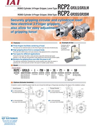
1. Securely gripping circular and cylindrical load!
New electrical 3-Finger grippers
also allow for easy adjustment
of gripping force!
-0.05
ø10 0
ø55
ø29
9
(32)
2 30±0.05
5 (25)
2-M5
3-ø4.5
120°
120°
ø45
18
ø10H8 depth 25
ø73
-0.05
ø10 0
ø29
9
(32)
30±0.05
5 (25)
2-M5
2
18
ø62
120°
120°
3-ø5.5
ø10H8 depth 25
ROBO Cylinder 3-Finger Gripper, Lever Type
ROBO Cylinder 3-Finger Gripper, Slide Type
Three fingers facilitate centering of load
The load can be centered easily as the three fingers grip the load simultaneously.
High gripping force from a compact body
The unique drive method using a worm gear produces a high gripping force from a compact body.
Two types for different applications
Maintains the gripping force even after the power is off
Shaft Bracket Flange Bracket
ø55
3-ø4.5
ø14
ø10h8
(15)
5
30
15 ±0.05
2
0
-0.05
ø10
ø45
120°
120°
(32)
3-ø5.5
ø14
ø10h8
(15)
5
30
15 ±0.05
ø62
2
-0.05
ø10 0
120°
120°
(32)
ø73
RCP2-GR3LS/GR3LM
RCP2-GR3SS/GR3SM
Features Example of Use
Actuator Model
RCP2 I
RCP2
GR3LS
GR3LS: Lever type (S size)
GR3LM: Lever type (M size)
GR3SS: Slide type (S size)
GR3SM: Slide type (M size)
I: Incremental
M
N: No cable
P:1m
S:3m
M:5m
Xnn: Specified length
Rnn: Robot cable
PM
PM: Pulse motor
P1
P1:RCP2-C
RCP2-CG
SB
SB: Shaft bracket
FB: Flange bracket
19
GR3LS:19°
GR3LM:19°
GR3SS:10mm
GR3SM:14mm
30
30: Gear ratio
1/30
Options (Actuator brackets)
Lever Type
A bracket is used to install the gripper body. You can choose the shaft type or flange type according to the shape of the installation surface.
For GR3LS/GR3SS
Unit model: RCP2-SB-GR3S
For GR3LM/GR3SM
Unit model: RCP2-SB-GR3M
For GR3LS/GR3SS
Unit model: RCP2-FB-GR3S
For GR3LM/GR3SM
Unit model: RCP2-FB-GR3M
Slide Type
Choose the "lever type" that offers a wide open/close range while achieving high-speed
operation, or the "slide type" that generates a high gripping force while ensuring excellent rigidity.
Combine with a
SCARA robot
to transfer
cylindrical load.
The self-lock mechanism maintains the current position even after the power is
switched off, so the load will not fall in the event of sudden power failure.
Model
Series Type code Encoder type Motor type Gear ratio Stroke Applicable controller Cable length Options
Sold & Serviced By:
ELECTROMATE
Toll Free Phone (877) SERVO98
Toll Free Fax (877) SERV099
www.electromate.com
sales@electromate.com
2. RCP2-GR3LS/GR3LM3-Finger gripper, lever type
Type Grip (Width: 62 mm/80 mm) Stroke 19° Maximum gripping force 18N/51N
Series Type Encoder type Motor output Gear ratio Stroke Applicable controller Cable Option
RCP2-GR3LS- I - PM - 30 - 19 - P1 - M - SB
(Example)
Options Common Specifications
ø3 +0.05
HOME
+0.05
100
2 0.5
Blank plug (setscrew M4 x 5)
Actuator width: 62 mm/80 mm, pulse motor
4
(Same on reverse side)
24
36
0 depth 3
0 depth 3
2-3+0.05
120°
Installation surface
-0.05
ø59 0
28
(19)
1.5 4-M5 depth 8
ø 57
0
8 0
14°
120°
2-ø3 +0.03
ø57
10 3-M4 (Effective depth 6)
ø45
(Same on reverse side)
112
84
Model specification items
Model / Specifications
Code Page
GR3LS (Lever type, S size)
48
62
48
Installation surface
(Same on opposite side)
4-ø4.5
62
ø18
ø76
9 6
50.5
31.5
7.5
-0.05
6
12
5°
3.5 8
2-M3
17.5
(129.5)
A
16
M8 (Effective depth 4)
Detail view of A (2 : 1)
36 78
1.5
64
0 depth 3
2-ø3 +0.03
4-M6 depth 12
34
ø3 +0.05
0
2-M4
-0.05
18
GR3LM (Lever type, M size)
4-ø5.5
80
48
0 depth3
2-3 +0.05
114
62
80
62
ø75
Installation surface
Installation surface
ø98
-0.05
77 0
(23.5)
7
14°
120°
40.5
120°
+0.05
100
2 0.5
3-M5 (Effective depth 7)
ø75
4
12
14.5
ø62
7
4
10 0
10
9
Installation surface
(Same on opposite side)
22
(136)
A
20
ø29
M8 (Effective depth 4)
HOME
Detail view of A (2 : 1)
5°
Dimensions
Caution
Applicable controller
Maximum
number of
controlled axis
Compatible
encoder type
Program
operation
Power-supply
voltage
Page
RCP2-C-GR3LS/GR3LM
RCP2-CG-GR3LS/GR3LM
1 axis Incremental Positioner 24VDC Back cover
Model
RCP2-GR3LS-I-PM-30-19-P1- -
RCP2-GR3LM-I-PM-30-19-P1- -
Size Encoder type
Incremental
S size
M size
Motor type
Pulse motor
Stroke
(°)
Open/close stroke
(one side)
(°)
Gear ratio
30 19 -14°~5°
Maximum gripping
force
(Note 2) (N)
Maximum open/close
speed (one side)
(Note 1) (°/sec)
200
18
51
* and in the model numbers shown above respectively indicate the cable length and applicable options.
Name
Shaft bracket
Flange bracket
Cover
Cover
SB
FB
Drive system
Positioning repeatability (Note 3)
Backlash
Base
Cable length (Note 4)
Weight
Operating temperature/humidity
Worm gear + Worm wheel gear
±0.01°
1° max. per side (Pressure is constantly applied toward the open side via spring.)
Material: Aluminum with white alumite treatment
N: No cable, P: 1 m, S: 3 m, M: 5 m, X : Specified length, R : Robot cable
GR3LS:0.6kg/GR3LM:1.1kg
0 to 40°C, 85%RH max. (non-condensing)
1 RCP2-GR3LS/GR3LM
(Note 1) The speed when one side (finger) of the grippers is operated. The relative
operating speed is twice this value.
(Note 2) The sum of gripping forces of all fingers when the gripping-point distance is 10
and overhang distance is 0. The actual allowable gripping force will vary
depending on the applicable conditions. Refer to the back cover for details.
(Note 3) Positioning repeatability of positioning operations from the negative direction.
(Note 4) The maximum cable length is 20 m. Specify the desired length in meters (e.g.,
X08 = 8 m).
À
À
Á
Á
À Á
* During home return the actuator will return home
along a path running 1° outside of the shortest line
home, so be careful to prevent contact with
surrounding parts.
* During home return the actuator will return home
along a path running 1° outside of the shortest line
home, so be careful to prevent contact with
surrounding parts.
Applicable Controller Specification
(Same on reverse side)
(Same on reverse side)
(Same on reverse side)
(Same on reverse side)
Installation surface
Blank plug (setscrew M5 x 6)
Sold & Serviced By:
ELECTROMATE
Toll Free Phone (877) SERVO98
Toll Free Fax (877) SERV099
www.electromate.com
sales@electromate.com
3. RCP2-GR3SS/GR3SM 2
RCP2-GR3SS/GR3SM3-Fnger gripper, Slide type
Type Grip (Width: 62 mm/80 mm) Stroke 5mm/7mm 22N/102N
2-ø3 +0.03
(Same on
reverse side)
24
36
(Same on reverse side)
3-M3 depth 5
ST5
(Same on opposite side)
Blank plug (setscrew M4 x 5)
-0.05
6 0
-0.010 )
3-ø2.5h7 ( 0
4
2-3+0.05
0 depth 3
120°
ø76
70
-0.05
ø59 0
4
40
1.5 4-M5, depth 8
ø57
1.5
120°
104
0 depth 3
ø57
2
110
10
+0.05
100
2 0.5
45 3-M4 (Effective depth 6)
ø45
18
3.5 5
4 - 9
À Á
À
Á
Code Page
4-ø4.5
ø9 counterbore, depth 1.5
M8 (Effective depth 6)
62
Installation surface
Installation
62
48 surface
48
15 1.5
A
ST5
1.5
18
3.5 5
4 - 9
Á
62
48
15 1.5
B
HOME
Detail view of B (1.5 : 1)
Detail view of A (2 : 1)
ø75
HOME
47 78
2-ø3 +0.03
0 depth 3
(Same on
reverse side)
(Same on
reverse side)
(Same on reverse side)
ST7
-0.010)
25
-0.05
8 0
-0.05
(Same on opposite side)
4-M6, dept12
2-3+0.05
0 depth 3
3-ø2.5h7 ( 0
ø75
Installation
surface Installation surface
Installation surface
120°
120°
+0.05
100
2 0.5
3-M5(Effective depth 7)
Blank plug (setscrew M4 x 5)
118
125
2
77 0
4
48
1.5
53
12
80
62
62
80
3-M4 depth 5
ø98
4-ø5.5
ø62
4 - 11
1.5 22 1.5
7 8
A
ø9 counterbore, depth 1.5
M8 (Effective depth 6)
34
Detail view of A (2 : 1)
Name
À
Shaft bracket
Flange bracket
Cover
Cover
SB
FB
Options
Common Specifications
Worm gear + Worm wheel gear
±0.01mm
0.3 mm or less each side (The grippers are always kept open by a spring.)
Cross roller guide
<GRSS> Ma:3.8N • m / Mb:3.8N • m / Mc:3.0N • m
<GRSM> Ma:6.3N • m / Mb:6.3N • m / Mc:5.7N • m
Material: Aluminum with white alumite treatment
N: No cable, P: 1 m, S: 3 m, M: 5 m, X : Specified length, R : Robot cable
GR3SS:0.6kg / GR3SM:1.2kg
0 to 40°C, 85%RH max. (non-condensing)
(Same on Installation surface
reverse side)
Caution
Applicable controller
Maximum
number of
controlled axis
Compatible
encoder type
Program
operation
Power-supply
voltage
Page
RCP2-C-GR3SS/GR3SM
RCP2-CG-GR3SS/GR3SM
1 axis Incremental Positioner 24VDC Back cover
(Note 1) The speed when one side (finger) of the grippers is operated. The relative
operating speed is twice this value.
(Note 2) The sum of gripping forces of all fingers when the gripping-point distance is 0
and overhang distance is 0. The actual allowable gripping force will vary
depending on the applicable conditions. Refer to the back cover for details.
(Note 3) Positioning repeatability of positioning operations from the negative direction.
(Note 4) The maximum cable length is 20 m. Specify the desired length in meters (e.g.,
X08 = 8 m).
Applicable Controller Specification
Actuator width: 62 mm/80 mm, pulse motor
Model specification items
RCP2-GR3SS- I - PM - 30 - 10 - P1 - M - SB
(Example)
Maximum gripping force
Model / Specifications
Model
RCP2-GR3SS-I-PM-30-10-P1- -
RCP2-GR3SM-I-PM-30-14-P1- -
Size Encoder type
Incremental
S size
M size
Motor type
Pulse motor
Stroke
(mm)
Open/close stroke
(one side)
(mm)
Gear ratio
30 10
14
5
7
Maximum gripping
force
(Note 2) (N)
Maximum open/close
speed (one side)
(Note 1) (mm/sec)
40
50
22
102
* and in the model numbers shown above respectively indicate the cable length and applicable options.
Drive system
Positioning repeatability (Note 3)
Backlash
Guide
Allowable load moment
Base
Cable length (Note 4)
Weight
Operating temperature/humidity
Dimensions
GR3SS (Slide type, S size)
* During home return the actuator will return home
along a path running 0.5 mm outside of the
shortest line home, so be careful to prevent
contact with surrounding parts.
GR3SM (Slide type, M size)
* During home return the actuator will return home
along a path running 0.5 mm outside of the
shortest line home, so be careful to prevent
contact with surrounding parts.
ø9 counterbore, depth 1.5
M8 (Effective depth 6)
3-M3 depth 5
Series Type Encoder type Motor output Gear ratio Stroke Applicable controller Cable Option
Sold & Serviced By:
ELECTROMATE
Toll Free Phone (877) SERVO98
Toll Free Fax (877) SERV099
www.electromate.com
sales@electromate.com
4. Catalog No.: RCP2GR3LS-CJ0083-1A-Aug1805-1
Controller
Unit: mm
GR3LS I PM
Item Specification 35.0
ø5
Item Model
* The standard motor cable is a robot cable.
Model / Specifications
Specification Table
Options/Spare Parts
68.1
178.5
170.5
5.0
Controller
RCP2
Series
RCP2
Actuator type
Actuator’s
(type code) – (encoder type) – (motor type)
Controller Model
C
Type
O
Power-supply voltage
0:24VDC
P
I/O signal pattern
(Blank) :NPN
P :PNP
L Lever type (GR3LS/GR3LM) Slide type (GR3SS/GR3SM)
RCP2-GR3LS RCP2-GR3LM
20 30 40 50 60 70
25
20
15
10
5
60
50
40
30
20
Current-limiting value (%) Current-limiting value (%)
Gripping force P (N)
Gripping force P (N)
20 30 40 50 60 70
10
RCP2-GR3SS RCP2-GR3SM
20 30 40 50 60 70
25
20
15
10
5
20 30 40 50 60 70
120
100
80
60
40
20
F
L
F
External Dimensions
C: Built-in
drive-power
cutoff relay type
CG: External
drive-power
cutoff relay type
* This field can be left
blank unless the PNP
specification is
required.
Correlation Diagrams of Gripping Force and Current-limiting Value
* The graphs below show gripping forces measured at a 10-
mm point. The actual gripping force will decrease in
inverse proportion to the distance from the open/close
fulcrum.
Calculate the actual gripping force using the formula below:
Effective gripping force (S type) = P x 24 / (L + 14)
Effective gripping force (M type) = P x 28.5 / (L + 18.5)
P = Gripping force in the graph
L = Distance from the finger installation surface to the
gripping point
* The distance (L) from the finger
installation surface to the gripping point
must not exceed the following
dimensions:
GR3SS 50 mm or less
GR3SM 80 mm or less
Gripping force P (N)
Gripping force P (N)
Current-limiting value (%) Current-limiting value (%)
Controller series/type
Connected actuator
Input power supply
Power-supply capacity
Number of controlled axis
Control method
Positioning command
Position numbers
Backup memory
PIO
LED indicators
I/F power supply
Communication
Withstand voltage
Operating temperature
Operating humidity
Operating ambience
Weight
Accessory
Teaching pendant
Teaching pendant (deadman specification)
Simple teaching pendant
Data setting unit
PC software
Motor cable
Encoder cable
Encoder robot cable
RCA-T
RCA-TD
RCA-E
RCA-P
RCB-101-MW
CB-RCP2-MA
CB-RCP2-PA
CB-RCP2-PA -RB
RCP2-C/CG
RCP2 Series
24 VDC ± 10%
2 A max.
1 axis
Field-weakening vector control (patent pending)
Position number specification
Standard 16 points, maximum 64 points
Storage of position number data and parameters in non-volatile
memory. Serial E2PROM rewritable up to 100,000 times.
RCP2-C (CG): 10 dedicated inputs (10 points)
/ 11 dedicated outputs (10 points); selectable from 5 patterns
RDY (green), RUN (green), ALM (red)
External power supply: 24 V ± 10%, 0.3 A; insulated
RS485, 1 channel (terminated externally)
500 VDC, 10 MW
0 to 40°C
85%RH max. (non-condensing)
Free from corrosive gases
300g
PIO flat cable (2 m)
Sold & Serviced By:
ELECTROMATE
Toll Free Phone (877) SERVO98
Toll Free Fax (877) SERV099
www.electromate.com
sales@electromate.com