Breaking the Kubernetes Kill Chain: Host Path Mount
Iai cartesian icsa_icspa_specsheet
1. 41 ISPA/ICSPA Catalog
Q u a l i t y a n d I n n o v a t i o n
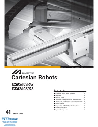
Cartesian Robots
ICSA2/ICSPA2
ICSA3/ICSPA3 C o n t e n t s
Cartesian Robot Series Contents 42
Features 43
Product Types 45
Two-Axes Configuration Unit Selection Table 47
Three-Axes Configuration Unit Selection Table 49
Points to Note 59
Explanation of Model Specification Items 61
Installation Method 63
System Configuration 65
Sold & Serviced By:
ELECTROMATE
Toll Free Phone (877) SERVO98
Toll Free Fax (877) SERV099
www.electromate.com
sales@electromate.com
2. ICSA/ICSPA Cartesian Robots
Two-Axes Configuration 67
Three-Axes Configuration 145
ICS(P)A3-BAMB1
ICS(P)A3-BBHB1
ICS(P)A3-BBMB1
ICS(P)A3-BBMB2
ICS(P)A3-BCHB1
ICS(P)A3-BCHB2
ICS(P)A3-BCHB3
ICS(P)A3-BCMB1
ICS(P)A3-BCMB2
ICS(P)A3-BCMB3
ICS(P)A3-BDHB1
ICS(P)A3-BDHB2
ICS(P)A3-BDHB3
ICS(P)A3-BEHB1
ICS(P)A3-BEHB2
ICS(P)A3-BEHB3
ICS(P)A3-BEMB2
ICS(P)A3-BEMB3
ICS(P)A3-BFMB1
ICS(P)A3-BFHB2
ICS(P)A3-BFHB3
ICS(P)A3-BAMS1
ICS(P)A3-BBHS1
ICS(P)A3-BBMS1
ICS(P)A3-BCHS1
ICS(P)A3-BCHS3
ICS(P)A3-BCMS1
ICS(P)A3-BCMS3
ICS(P)A3-BDHS1
ICS(P)A3-BDHS3
ICS(P)A3-BEHS1
ICS(P)A3-BEHS3
ICS(P)A3-BEMS1
ICS(P)A3-BEMS3
ICS(P)A3-BFHS1
ICS(P)A3-BFHS3
ICS(P)A3-G1JHB1
ICS(P)A3-G1JHB2
ICS(P)A3-G1JHB3
ICS(P)A3-G2JHB1
ICS(P)A3-G2JHB2
ICS(P)A3-G2JHB3
ICS(P)A3-G1JHS1
ICS(P)A3-G1JHS2
ICS(P)A3-G1JHS3
ICS(P)A3-G2JHS1
ICS(P)A3-G2JHS2
ICS(P)A3-G2JHS3
ISPA/ICSPA Catalog 42
Cartesian Robot Series Contents
ICSA2(ICSPA2)-BAH
ICSA2(ICSPA2)-BAM
ICSA2(ICSPA2)-BBH
ICSA2(ICSPA2)-BBM
ICSA2(ICSPA2)-BCH
ICSA2(ICSPA2)-BCM
ICSA2(ICSPA2)-BDH
ICSA2(ICSPA2)-BEH
ICSA2(ICSPA2)-BEM
ICSA2(ICSPA2)-BFH
ICSA2(ICSPA2)-SAH
ICSA2(ICSPA2)-SAM
ICSA2(ICSPA2)-S1CH
ICSA2(ICSPA2)-S1CM
ICSA2(ICSPA2)-S2CH
ICSA2(ICSPA2)-SGH
ICSA2(ICSPA2)-ZAH
ICSA2(ICSPA2)-ZAM
ICSA2(ICSPA2)-Z1CH
ICSA2(ICSPA2)-Z1CM
ICSA2(ICSPA2)-Z2CH
ICSA2(ICSPA2)-ZDH
ICSA2(ICSPA2)-ZGH
ICSA2(ICSPA2)-ZHH
ICSA2(ICSPA2)-YAH
ICSA2(ICSPA2)-YAM
ICSA2(ICSPA2)-YCH
ICSA2(ICSPA2)-YCM
ICSA2(ICSPA2)-YGH
ICSA2(ICSPA2)-G1JH
ICSA2(ICSPA2)-G2JH
XYB (Y-Axis Base Mount) Type
XYS (Y-Axis Slider Mount) Type
XZ (Z-Axis Base Mount) Type
YZ (Y-Axis Slider Mount) Type
XYG (Gantry) Type
X-Y Two-Axes Configuration
X-Z Two-Axes Configuration
Y-Z Two-Axes Configuration
X-Y Two-Axes Gantry
Configuration
69
71
73
75
77
79
81
83
85
103
105
107
109
111
113
115
117
119
121
123
125
127
129
131
133
135
137
139
141
143
Z-Axis Base Mount Type
(Z-Axis Slider Flexible)
Z-Axis Slider Mount Type
(Z-Axis Body Flexible)
Z-Axis Base Mount Type
(Z-Axis Slider Flexible)
Z-Axis Slider Mount Type
(Z-Axis Body Flexible)
X-Y Base Mount (XYB) + Z-Axis
Configuration
X-Y Gantry (XYG) + Z-Axis
Configuration
147
149
151
153
155
157
159
161
163
165
167
169
171
173
175
177
179
181
183
185
187
189
191
193
195
197
199
201
203
205
207
209
211
213
215
217
219
221
223
225
227
229
231
233
235
237
239
* In the above model names, indicates the configuration direction (1 through 4).
ICSA2(ICSPA2)-BKH
ICSA2(ICSPA2)-BKM
ICSA2(ICSPA2)-BLH
ICSA2(ICSPA2)-BLM
ICSA2(ICSPA2)-BPH
ICSA2(ICSPA2)-BPM
ICSA2(ICSPA2)-BQH
ICSA2(ICSPA2)-BQM
87
89
91
93
95
97
99
101
New Models
added!
Sold Serviced By:
ELECTROMATE
Toll Free Phone (877) SERVO98
Toll Free Fax (877) SERV099
www.electromate.com
sales@electromate.com
3. ICSA/ICSPA Cartesian Robots
Cartesian Robot Series Features
The ICSA/ICSPA Cartesian robots are configuration units based on the two-axes and three-axes configuration patterns that
are frequently used. These actuators come pre-wired with brackets attached, so they can be installed in your equipment and
used immediately after delivery.
1. Configuration Variations
Fifty-seven standard configuration types are provided, so the user can find the model best suited to existing conditions. We
can also build custom configurations not currently represented in the standard range. Please contact us regarding your
specifications.
Two-Axes Configuration Type
Two-axes configuration units are available in 31 types,
each combining one of five configuration patterns with
different speeds and motor capacities.
XYB Type XYS Type XZ Type ZY Type XYG Type
XYB (Y-Axis Base Mount)Type
Point 1 There are four patterns of Y-axis configuration directions to choose
Point 2 Select the Y-axis wiring specification from the two options of self-standing
43 ISPA/ICSPA Catalog
Configuration Direction
A basic configuration type where the Y-axis base is
mounted to the X-axis bracket.
This actuator operates with a device or Z-axis
attached to the Y-axis slider.
from (refer to the figure shown to right).
cable (standard) and cable track.
XYS (Y-Axis Slider Mount) Type
Configuration direction 1
(Range of operation)
Configuration direction 2
(Opposite of 1)
(Range of operation)
Configuration direction 4
(Opposite of 3)
(Range of operation)
Configuration direction 3
(Y-axis installed
on opposite side)
(Range of operation)
The Y-axis slider is mounted to the X-axis bracket
in a manner allowing the Y-axis to move.
Use this type when the Y-axis itself must be moved
back and forth to avoid an obstacle, etc.
Point 1 There are four patterns of Y-axis configuration directions to choose
from (refer to the figure shown to right).
Point 2 Only the self-standing cable option is available for the Y-axis wiring
specification.
Configuration Direction
Sold Serviced By:
ELECTROMATE
Toll Free Phone (877) SERVO98
Toll Free Fax (877) SERV099
www.electromate.com
sales@electromate.com
4. ICSA/ICSPA Cartesian Robots
Since the Z-axis comes standard with a brake, the
slider will not drop even when the power is turned off.
The maximum stroke is 2500 mm for the X-axis and
500mm for the Z-axis.
(Consult IAI if you need a longer stroke.)
Since the Z-axis comes standard with a brake, the
slider will not drop even when the power is turned off.
The standard wiring specification of the Z-axis is the
self-standing cable, but the cable track can also be
used (custom order).
The Z-axis base can be mounted (custom order).
Point 1
Point 2
Point 1
Point 2
Point 3
The Y-axis o f the XYB type i s placed f lat a nd a s upport guide i s
attached at the tip of the Y-axis.
Use this type for transferring heavy objects or when the Y-axis stroke
is long and the tip might sag.
A maximum of 40 kg can be transferred.
The maximum stroke is 2500 mm for the X-axis and
1200 mm for the Y-axis.
(Consult IAI if you need a longer stroke.)
ISPA/ICSPA Catalog 44
XZ (Z-Axis Base Mount) Type
YZ (Y-Axis Slider Mount) Type
The Z-axis (vertical axis) is positioned vertically on the X-axis.
Use this type in such applications as inserting loads into a stocker or
moving a pallet up and down.
XYG (Gantry) Type
The Y-axis is positioned on its side and its slider is connected to the
slider of the Z-axis (vertical axis).
Since the Z-axis moves vertically, this type can be fitted with a chuck or
other device on the Z-axis for transfer of loads.
Three-Axes Configuration Type
Three-axes c onfiguration units
are available in 102 types, each
combining either the basic XYB
(Y-axis base mount) type or
high-rigidity XYG ( gantry) type
with a Z-axis (vertical axis) of
high-speed, m edium-speed or
low-speed specification,
providing a maximum load
capacity of 19 kg.
Consult IAI for details
on three-axes
combined types.
Point 1
Point 2
Four-Axes Configuration Type
We a lso offer four-axes
configuration t ypes, which
are three-axes c onfiguration
units with a rotating axis
integrated with the Z-axis.
Please advise u s of y our
desired conditions, and we
will select the best
configuration and s ubmit
drawings.
Sold Serviced By:
ELECTROMATE
Toll Free Phone (877) SERVO98
Toll Free Fax (877) SERV099
www.electromate.com
sales@electromate.com
8. ICSA/ICSPA Cartesian Robots
ISPA/ICSPA Catalog 48
3 4 5 Applicable type
100 ~ 600
100 ~ 600
200 ~ 800
200 ~ 800
200 ~ 800
800 ~ 2000
200 ~ 800
1000 ~ 2500
Configuration type Page
X-axis stroke
(mm)
100 ~ 600
100 ~ 600
200 ~ 800
200 ~ 800
200 ~ 800
200 ~ 800
800 ~ 2000
300 ~ 1000
300 ~ 1000
1000 ~ 2500
Maximum speed (X-axis/Y-axis)
(mm/sec)
800/800
400/400
*1000/800
*500/400
*1000/1000
*500/500
*1000/1000
*1000/1000
*500/500
*1000/1000
X-axis stroke
(mm)
100 ~ 600
100 ~ 600
200 ~ 800
200 ~ 800
200 ~ 800
300 ~ 800
Maximum speed (X-axis/Y-axis)
(mm/sec)
800/800
400/400
*1000/1000
*500/500
*1000/1000
1000/1000
Configuration type Page
Y-axis stroke
(mm)
100 ~ 400
100 ~ 400
200 ~ 700
200 ~ 700
200 ~ 700
Maximum speed (Y-axis/Z-axis)
(mm/sec)
800/400
400/200
1000/500
*500/250
1000/500
Configuration type Page
YAH
YAM
YCH
YCM
YGH
X-axis stroke
(mm)
1000 ~ 2500
1000 ~ 2500
Maximum speed (X-axis/Y-axis)
(mm/sec)
*1000/1000
*1000/1000
Configuration type Page
G1JH
G2JH
X-axis stroke
(mm)
Maximum speed (X-axis/Z-axis)
(mm/sec)
800/400
400/200
*1000/500
*500/250
*1000/500
*1000/500
1000/500
*1000/500
Configuration type Page
Caution
……e maximum speed of some long-stroke types (indicated by *) …as been reduced to pre…ent
t…e ball scre… from r eac…ing a dangerous speed… … nce t…e desired type …as b een s elected…
c…eck t…e actual speed specification on t…e page corresponding to t…e selected type…
BAH
BAM
BBH
BBM
BCH
BCM
BD H
BEH
BEM
BFH
SAH
SAM
S1CH
S1CM
S2CH
SG H
ZAH
ZAM
Z1CH
Z1CM
Z2CH
ZDH
ZGH
ZHH
BK
H
BK M
BL H
BL M
BP H
BP M
BQ H
BQ M
Sold Serviced By:
ELECTROMATE
Toll Free Phone (877) SERVO98
Toll Free Fax (877) SERV099
www.electromate.com
sales@electromate.com
9. ICSA/ICSPA Cartesian Robots
Three-Axes Configuration Unit Selection Table
Start from and move toward right as you confirm each condition to select a desired type.
2 3 4 5
High-Speed
Type
800~1000
mm/sec
49 ISPA/ICSPA Catalog
3.0
8.6 7.3
9.0 7.9
7.6 6.3
9.0 6.9
9.0 5.8
9.0
9.0
8.4
9.0
9.0
3.0
3.0
3.0
3.0
9.0
9.0
How to Select a Unit (Explanation of the Table)
[ Z-Axis Base Mount ]
1
Select the installation method of Z-axis
from the followings:
1
1
Check the Y-axis stroke and load capacity.
(If the condition is not satisfied, go down to the line
below and select larger load capacity.)
5
[Z-Axis Base Mount]
(The Z-axis base is mounted to the Y-axis slider: The Z-axis slider moves vertically.)
[Z-Axis Slider Mount]
(The Z-axis slider is mounted to the Y-axis slider: The Z-axis itself moves vertically.)
Refer to page 45 for the X/Y-Axis configuration directions.
Select the X/Y-Axis and Z-Axis wiring specifications from the two options to the right.
Only cable track is available for X/Y-Axis type D, F, 1J, and 2J.
Only Self-standing cable is available for Z-Axis Slider Mount Type.
We can also build custom configurations not currently represented in the standard range.
Please contact us regarding your specifications.
Check the X-axis stroke.
If the condition is not satisfied, go down to the line below and
select larger type.
*( ) specifies the case of BDHB or BFHB.
6
Select the Z-axis type from High-speed,
Mid-speed, and Low-speed. (The Slider Mount Type is available only in Mid-speed and Low-speed.
2
7 Check the maximum speed for X-axis and Y-axis.
You have selected the type that satisfies
all your desired conditions.
8
Select the load capacity for Z-axis
(total weight of load and jig)
3
4 Select the desired Z-axis stroke from the chart.
SC: Self-standing cable
CT: Cable track
* Refer to page 241.
100 200 300 400 500 600 700 800~1200
- - - -
- - -
- -
- - - - -
- - - - - - -
- - -
- -
- - -
- -
- - -
- -
- - -
- -
- -
- - - - -
- - - - - - -
100~300
100~400
100~500
100~600
100~600
100
200
300
400
500
1000~600
3kg or less
9kg or less
Z-Axis
Z-Axis Speed Type
Load Capacity Stroke (mm)
Y-Axis Stroke (mm)
Load Capacity (kg) Load Capacity (kg)
Cartesian Robots Series
If the condition is not satisfied, go down to the line below and
select larger type.
Sold Serviced By:
ELECTROMATE
Toll Free Phone (877) SERVO98
Toll Free Fax (877) SERV099
www.electromate.com
sales@electromate.com
10. ICSA/ICSPA Cartesian Robots
Conditions
The Z-Axis is subject to base mount.
Allowable tip load : 2kg
Speed : 800mm/sec or more
Z-Axis Stroke : 200mm
Y-Axis Stroke : 500mm
X-Axis Stroke : 700MM
The crossed column for Z-Axis stroke 100~300mm and Y-Axis stroke
500mm reads --- (Not applicable), so apply the line below. Since the
Y-Axis stroke on the line covers 500mm, shift to the right.
The X-Axis stroke is applicable up to 800mm, so shift to the right.
The maximum speed for X-Axis/ Y Axis is 1000mm/sec and satisfy the
condition. Shift to the right.
As a result, Unit Type [BCHB1H] is the selected suitable model.
Note The numbers in ( ) in X-Axis stroke in the chart below are for models in ( ) listed in Applicable Type's configuration type.
Example: If the X-Axis stroke in the above example is 1000mm, configuration Applicable Type will be [BDHB1H].
6 7 8 Applicable Type
Configuration Type Page
ISPA/ICSPA Catalog 50
Example of Selection
1
2
3
4
5
6
7
8
Select the chart of [Z-Axis Base Mount Type].
Select High-speed type since the desired speed is 800mm/sec.
Select 3kg or less since the load capacity is 2kg.
Move the line for 100~300 to the right since Z-Axis stroke is 200mm.
ICSA [ICSPA] 3-BB HB1H
ICSA [ICSPA] 3-BC HB1H(BD HB1H)
ICSA [ICSPA] 3-BE HB1H(BF HB1H)
ICSA [ICSPA] 3-G1JHB1H
ICSA [ICSPA] 3-G2JHB1H
ICSA [ICSPA] 3-BC HB3H (BD HB3H)
ICSA [ICSPA] 3-BE HB3H (BF HB3H)
ICSA [ICSPA] 3-BC HB3H (BD HB3H)
ICSA [ICSPA] 3-BE HB3H (BF HB3H)
ICSA [ICSPA] 3-BC HB3H (BD HB3H)
ICSA [ICSPA] 3-BE HB3H (BF HB3H)
ICSA [ICSPA] 3-BC HB3H (BD HB3H)
ICSA [ICSPA] 3-BE HB3H (BF HB3H)
ICSA [ICSPA] 3-BE HB3H (BF HB3H)
ICSA [ICSPA] 3-G1JHB3H
ICSA [ICSPA] 3-G2JHB3H
*( ) is for the type BDHB or BFHB.
X-Axis Stroke Maximum Speed (X-axis / Y-axis)
(mm) (mm/sec)
1000/800
1000/1000
1000/1000
1000/1000
1000/1000
1000/1000
1000/1000
1000/1000
1000/1000
1000/1000
1000/1000
1000/1000
1000/1000
1000/1000
1000/1000
1000/1000
200~800
200~800 (800~2000)
300~1000 (1000~2500)
1000~2500
200~800 (800~2000)
300~1000 (1000~2500)
200~800 (800~2000)
300~1000 (1000~2500)
200~800 (800~2000)
300~1000 (1000~2500)
200~800 (800~2000)
300~1000 (1000~2500)
300~1000 (1000~2500)
1000~2500
Sold Serviced By:
ELECTROMATE
Toll Free Phone (877) SERVO98
Toll Free Fax (877) SERV099
www.electromate.com
sales@electromate.com
19. ICSA/ICSPA Cartesian Robots
Cartesian Robot Series Points to Note
Notes on Catalog Specifications
Speed Speed refers to the specified speed at which the actuator slider will move.
Positioning Repeatability Positioning repeatability refers to the positioning accuracy of repeated movements to a
59 ISPA/ICSPA Catalog
The slider accelerates from a stationary state, and once the specified speed is reached it
will maintain that speed until the specified position (immediately before the target
position), where it will begin decelerating to stop at the target position.
Caution
With all Cartesian robot models, the maximum speed will not change even when the load placed on the slider is changed.
The time needed to reach the specified speed will vary according to the acceleration (deceleration).
If the travel distance is short, the specified speed may not be reached.
With a long-stroke axis, the maximum speed will drop to avoid reaching a dangerous speed.
(If you are using a 600 or longer stroke, check the maximum speed for the applicable stroke.)
When calculating the travel time, consider acceleration, deceleration and stabilization periods in addition to the travel
time at the specified speed. (Refer to pages 39 and 40 for the method to calculate travel time.)
Speed can be set in increments of 1 mm/sec in a program.
Acceleration/Deceleration Acceleration refers to the rate of change of speed when the speed rises
from zero (stationary state) to the specified speed.
Deceleration refers to the rate of change of speed when the specified
speed drops to zero (stationary state).
Caution
Increasing the acceleration (deceleration) will shorten the duration the actuator accelerates (decelerates) and decrease
the travel time. However, doing so will also cause rapid acceleration (deceleration), resulting in increased shock.
The load capacity of each type assumes operation at the rated acceleration and maximum speed.
(The rated acceleration is 0.3 G for the standard type and 0.15 G when the lead is 4 or 5 mm.)
The ICSA2/ICSPA2 supports a maximum acceleration of 1.0 G.
The load capacity will decrease when the specified acceleration is increased beyond the rated acceleration.
For the load capacity at a raised acceleration, refer to the table of load capacity by acceleration corresponding to each
actuator type.
Acceleration can be set (specified) in increments of 0.01 G for each position movement in a program.
pre-stored position.
This is not the same as absolute positioning accuracy, so exercise caution.
Home The home is set on the motor side for the standard specification, or on the counter-motor
side for the reversed-home specification.
Caution
• The incremental actuator always requires homing every time the power is reconnected. (Homing is not required for the
absolute type even after reconnecting the power.)
• During homing the slider (or rod or arm) will move to the mechanical end before reversing, so be careful to prevent
contact with surrounding parts.
• Note that changing the home position from the standard to reverse homing specification will require the actuator to be
returned to IAI for adjustment.
Duty IAI recommends that our actuators be used at a duty of 50% or less as a guideline in view
of the relationship of service life and accuracy.
Duty (%) = Acceleration / Deceleration Time
Motion time + Inactivity x 100
Sold Serviced By:
ELECTROMATE
Toll Free Phone (877) SERVO98
Toll Free Fax (877) SERV099
www.electromate.com
sales@electromate.com
23. ICSA/ICSPA Cartesian Robots
Cartesian Robots Installation Method
Two-Axes Configuration
XYB type
Affix the actuators using the through holes provided on the bottom
surface of the X-axis.
BAH, BAM : ø7 (P15 ISA-SXM Refer to the bottom plan view.)
BBH, BBM : ø9 (P18 ISA-MXM Refer to the bottom plan view.)
BCH, BCM : ø9 (P19 ISA-MXM Refer to the bottom plan view.)
BDH, : ø9 (P20 ISA-MXMX Refer to the bottom plan view.)
BEH, BEM : ø9 (P26 ISA-LXM Refer to the bottom plan view.)
BFH, : ø9 (P28 ISA-LXMX Refer to the bottom plan view.)
63 ISPA/ICSPA Catalog
XYS type
XZ type YZ type
XYG type
ICSA2/ICSPA2/ICSA3/ICSPA3
BKH, BKM
BLH, BLM
BPH, BPM
BQH, BQM
Affix the actuators using the through holes provided on the bottom
surface of the X-axis.
ZAH, ZAM : ø7 (P15 ISA-SXM Refer to the bottom plan view.)
Z1CH, Z1CM : ø9 (P18 ISA-MXM Refer to the bottom plan view.)
Z2CH : ø9 (P19 ISA-MXM Refer to the bottom plan view.)
ZDH, : ø9 (P20 ISA-MXMX Refer to the bottom plan view.)
ZGH : ø9 (P26 ISA-LXM Refer to the bottom plan view.)
ZHH : ø9 (P28 ISA-LXMX Refer to the bottom plan view.)
Affix the actuators using the through holes provided on the bottom
surface of the X-axis.
SAH, SAM : ø7 (P15 ISA-SXM Refer to the bottom plan view.)
S1CH, S1CM : ø9 (P18 ISA-MXM Refer to the bottom plan view.)
S2CH : ø9 (P19 ISA-MXM Refer to the bottom plan view.)
Affix the actuators using the threaded holes provided on the bottom
surface of the actuator.
YAH, YAM : M6 (P16 ISA-SYM Refer to the bottom plan view.)
YCH, YCM : M8 (P22 ISA-MYM Refer to the bottom plan view.)
YGH : M8 (P32 ISA-LYM Refer to the bottom plan view.)
Affix the actuators using the through holes provided on the bottom
surface of the X-axis (driving shart / driven shaft).
G1JH (Driving shaft) : ø9 (P30 ISA-LXUWX Refer to the bottom plan view.)
(Driven shaft) : ø7 (P15 ISA-SXM Refer to the bottom plan view.)
G2JH (Driving shaft) : ø9 (P30 ISA-LXUWX Refer to the bottom plan view.)
(Driven shaft) : ø7 (P15 ISA-SXM Refer to the bottom plan view.)
Sold Serviced By:
ELECTROMATE
Toll Free Phone (877) SERVO98
Toll Free Fax (877) SERV099
www.electromate.com
sales@electromate.com
24. ICSA/ICSPA Cartesian Robots
ISPA/ICSPA Catalog 64
Three-Axes Configuration
XYB+Z Axis type
Affix the actuators using the through holes provided on the bottom surface of the X-axis.
BAMS : ø7 (P15 ISA-SXM Refer to the bottom plan view.)
BB : ø9 (P18 ISA-MXM Refer to the bottom plan view.)
BC : ø9 (P19 ISA-MXM Refer to the bottom plan view.)
BD : ø9 (P20 ISA-MXMX Refer to the bottom plan view.)
BE : ø9 (P26 ISA-LXM Refer to the bottom plan view.)
BF : ø9 (P28 ISA-LXMX Refer to the bottom plan view.)
XYG+Z Axis type
Affix the actuators using the through holes provided on the bottom surface of the X-axis (driving shaft / driven shaft).
G1JH (Driving shaft) : ø9 (P30 ISA-LXUWX Refer to the bottom plan view.)
(Driven shaft) : ø7 (P15 ISA-SXM Refer to the bottom plan view.)
G2JH (Driving shaft) : ø9 (P30 ISA-LXUWX Refer to the bottom plan view.)
(Driven shaft) : ø7 (P15 ISA-SXM Refer to the bottom plan view.)
Sold Serviced By:
ELECTROMATE
Toll Free Phone (877) SERVO98
Toll Free Fax (877) SERV099
www.electromate.com
sales@electromate.com
25. ICSA/ICSPA Cartesian Robots
Cartesian Robots Series System Configurations
Actuator Controller Options
ICSA2 Series
ICSPA2 Series
ICSA3 Series
ICSPA3 Series
65 ISPA/ICSPA Catalog
X-SEL
P-Driver
PC Software
PDR-101-MW
Motor Cable
Encoder Cable
Teaching pendant
IA-T-X
PC Software
IA-101-X-MW
IA-101-X-CW
* Operating with P-Driver requires as
many P-Driver controller as the
number of axis to operate.
Sold Serviced By:
ELECTROMATE
Toll Free Phone (877) SERVO98
Toll Free Fax (877) SERV099
www.electromate.com
sales@electromate.com