SlideShare a Scribd company logo
1 of 20
CHAPTER 3
OVERALL INTERNSHIP EXPERIENCE, PRACTICALKNOWLEDGE
3.1 Virtualization Desktop Infrastructure
VDI was the first project I have been exposed to. It was Library project for Addis Ababa University
at College of Health Science. The projects objective was to bring the latest technology to our
country especially in education sector since it is cost efficient.
Virtualization is combined environment to manage all resources from one interface. And it can be
seen like a big computer consisting of three main important things. These are:
 RAM – The ability to process many things at one time.
 Memory – The capacity to store files
 Processor – The brain of the system which processes different tasks.
At the time I started working, all the passive works including the civil work, design and supply of
equipment’s were completed. The first thing I started doing was to be familiar with the working
environments and began my work with reading the floor designs which gives brief description of
where the thin clients are placed and how they are interconnected with the server room. From the
design I understood that the project design was divided into two wings. i.e. The right wing and the
left wing where the thin clients, cameras, IP-TV, smart boards and AC’s are placed.
Right Wing Server Room Left Wing
Fig 2. Floor Plan for CHS Library Project
The first task given from my supervisor Mr.Abiy was to label thin clients with respect to their
cablings from the patch panel inside the rack. It was that time when I learned to operate with
Labeling machine. There were 350 thin clients which can be able to support the same number of
students at one time.
On my earlier working days, one thing I observed was that it need very great care to check the load
checkup with power supply before starting up the electric power. It was great experience when I
saw expert in electrical engineer came and check the load and capacity by using software.
The first time the engineer from client side came and checked the power connectivity, he couldn’t
verify that we were ready to start the server. He told us to change the power cable, which takes
power from the Ethiopian Electric Power Corporation (EEPCo) to the Power Distribution Unit
(PDU), from which the server takes power. Saying that it was insufficient to carry that much of
power which the system requires. So, we changed the cable to newer one and it was good this time
he came up to check and program the PDU. After that we were able to start the whole system to
start with the active works.
3.2 Technical Details of VDI
3.2.1 How does VDI work?
Virtualization is centralized desktop delivery solution. The concept of VDI is to store and run
desktop workloads including a windows client operating system, applications, and data in a server
based virtual machine (VM) in a data center and allow user to interact with the desktop presented
onto a user via Remote Desktop Protocol (RDP).
With VDI, a virtual desktop is isolated from the client’s device and runs in a VM maintained in a
data center. Here, the device can be desktop, laptop or thin client. A VDI user interacts with one’s
virtual desktop through RDP which provides a rich desktop experience. Similar to session-based
remote desktops, VDI provides a server session with a full fidelity desktop environment that is
virtualized within a server-based hypervisor. The premise on VDI is that all users are running
virtual desktops on VM’s. The key technical components making a VDI reality include:
 Windows Server 2012 R2 with Hyper-V: A virtualization host which runs VM’s and is
essentially a grid in the virtualization solution infrastructure.
 Microsoft Application Virtualization: A dynamic application deployment vehicle based on
user profiles and transparent to local operating system
 Microsoft Remote Desktop Services: A single and consistent URL for accessing resources
published in multiple RDSHs and terminal servers
 System Center Management Suite with Virtual Machine Manager (SCVMM): is a
comprehensive management solution for managing enterprise IT life cycle. And it
simplifies the deployment, provisioning and management of virtualization hosts and VM’s.
In VDI deployment, there are two models:
 In Static mode, there is one-to-one mapping of VM’s to users. Each user is assigned with
a designated VM. Since VM’s are commonly stored on a Storage Area Network (SAN)
and execute on a server, a larger number of users will likely to significant SAN
requirements.
 In a Dynamic architecture, on the other hand, there is only one master image of the desktop
stored. All user personalization, profile, applications, etc. are stored separately from
desktop, a VM cloned from the master image is combined with the user’s personal data
and applications dynamically delivered to the user device based on roaming profiles. This
delivers a personalized desktop experience by dynamically provisioning a base image. It
simplifies the overall VM management by reducing the number of desktop images
maintained.
For the library project at college of health science at Addis Ababa University, we deployed the
dynamic mode since the students do not sit on the same spot every time they come to the library.
So, they will be authenticated before login to their account. This enables all students the
personalized desktop experience to store their files on their VM.
3.2.2 Considerations for VDI solution:
 Infrastructure with hypervisor hosts
 Virtual machine management
 Application Provisioning
 Connection Management
 Image management
 Licensing
3.3 Power Unit
the VDI uses 3 phase wire which came from Ethiopian Electric Power Corporation. The Power
goes to the PDU through breakers mounted. all equipment's use the uninterruptible power supply
since they can be easily damaged if we supplied them with under rated or over rated power.
There is load balancing for the power supply. And the power distribution unit capacity was
169KVA, which will be only about 20% to be used by the system. So, it’s enough to supply the
power required by all devices inside the server room and thin clients used by end users.
The PDU consists of battery to store power in case the power is down from the line, so that the
service won’t be disrupted, and no machine fails due to the power fluctuations.
Since the power usage of the project is centralized in the server room, it produces much heat. So,
it requires cooling system. That’s why air conditioners needed to be automatic. And since the
project is deployed for medical students in the library, it is required that the hot air to be sucked
out and recycled to environment by taking in cool air which creates good environment and make
the students to effectively study there. That’s why it’s used LG – Inverters which is the best air
conditioners in the market.
3.4 Servers
3.4.1 Dell M1000e
This VDI project used Dell M1000e dell blade enclosure. The Dell PowerEdge M1000e Modular
Blade Enclosure is the rock-solid foundation for Dell’s blade server architecture, providing an
extremely reliable, flexible and efficient platform for building any IT infrastructure. The M1000e
enclosure is built from the ground up to combat data center sprawl and IT complexity, delivering
one of the most energy efficient, flexible and manageable blade server implementations on the
market.
The system can include up to 16 half-height blades (server modules), eight full-height blades, or a
mixture of the two blade types. To function as a system, a blade is inserted into a Dell PowerEdge
M1000e enclosure (chassis) that supports power supplies, fan modules, a Chassis Management
Controller (CMC) module, and at least one I/O module for external network connectivity. The
power supplies, fans, CMC, optional iKVM module, and I/O modules are shared resources of the
blades in the enclosure.
Enclosure represents an evolution of the entire rack-mounted infrastructure consolidating and
repackaging featured infrastructure elements-computing, storage, networking, and power into a
single infrastructure in a box that accelerates data center integration and optimization. The Blade
System enclosure infrastructure is adaptive and scalable.
Dell also offered some Cisco Catalyst switches for this blade enclosure. Cisco offers a range of
switches for blade -systems from the main vendors.
An M1000e enclosure offers several ways for management. The M1000e offers ‘out of band’
management: a dedicated VLAN for management. The server has two-part network LAN. The
storage and servers are connected through, Blade switch. File Servers are dedicated servers used
to store end user’s files they have four cables from which two of the cables are used to connect to
storage and the other two cables are used to give space to machines. The servers have two network
cards to control the switches. There is back bone link between the two switches.
Fig. 4 Front of M1000e Blade Enclosure Fig. 5 Back of Enclosure
For management, there is Chassis Management Controller(CMC), used to manage server,
networks and storage. And this Management is conducted by using Vmware hypervisor. The
hypervisor takes too small size. Only about 300Mb’s. The hypervisor for management is vSphere.
The CMC modules in the enclosure offer management ethernet and do not rely on network
connections made via I/O switches inside the blade. In this project case, physically isolated LAN
is created for management allowing management access to all enclosures even when the entire
infrastructure is down. Each M1000e chassis can hold two CMC modules.
3.4.2 Power Edge M630
Inside the blade enclosure we used 7 of M630 blade servers which deliver the compute power the
client demanding applications require. It is Designed for use with the PowerEdge M1000e blade
enclosure, the M630 offers exceptional scalability in environments ranging from IT as a service
providers and private clouds to remote and branch offices.
Fig. 6 Blade Enclosure and Power Edge M630
Blade Enclosure M1000e
Power Edge
M630 Servers
On the servers we used VMware ESXi, the industry leading, purpose built bare metal hypervisor.
ESXi is installed directly onto physical server enabling it to be partitioned into multiple logical
servers referred to as Virtual Machines. Virtual servers are hosted on physical server.
The VMware ESXi acts as an Operating System. It creates a layer to give storage and allows to go
to the network. In this project, we have 7 Virtual Machines. To present storage to windows, we
use ESXi Software.
3.5 SCv2080 Storage System
The other part of the VDI is Storage where data are going to be kept. The storage used here is
block storage, which is an IP storage. The IP Storage is approach to use the IP over storage area
network (SAN). There are duplicate of the storage just to back up the first memory in case it is
failed or corrupted due to different reasons.
The SCv2080 storage system provides the central processing capabilities for the Storage Center
Operating System (OS) and management of RAID storage. The Storage Center OS generates alert
messages for temperature, fan, drive, power, and storage controller conditions. Use the Dell
Storage Client to view these alerts. The SCv2080 also has LED indicators that signify possible
problems with the Storage Center. The storage system holds the physical drives that provide
Fig. 7 Storage Center
storage for the Storage Center. If additional storage is needed, the SCv2080 also supports a single
SC180 expansion enclosure.
To insert drives into storage center, there are certain steps to follow.
Step 1: Open the drawer by opening drawer latches.
Step 2: Unlock the key on the drive to be inserted as shown in Fig. 8 (a)
Step 3: Hold the drive by the driver carrier and slide it most of the way into the slot. And Using
both hands (thumbs and forefingers), apply downward pressure firmly and equally across the
driver carrier as shown in Fig. 8 (b)
Step 4: Close the drawer.
a) Locate the two lock-release buttons situated midway along the runners on each
side of the drawer.
b) Press the lock-release buttons inward and use your body to push the drawer
toward the chassis until the locks disengage.
c) Place your hands on the front bezel and continue to push the drawer inward
until the bezel is flush with the chassis and the front drawer locks engage like
as in Fig. 8 (c)
Fig. 8 Steps to insert drives
a b
c
The Storage system comes with two redundant power supply units, five redundant cooling fans,
and up to two redundant storage controllers. The storage controller contains multiple I/O ports that
provide communication with front -end servers and back-end storage.
iSCSI is an acronym for Internet small computer systems interface, an IP based storage networking
standard for linking data storage facilities. It’s used as an initiator to facilitate storage to be
controlled over distances.
3.6 Dell Compellent FS8600
The Dell Compellent FS8600 is uniquely suited to overcome the challenges presented by explosive
file data growth and file sprawl. With the combination of the Dell Fluid File System’s (FluidFS)
scale-out single namespace and Compellent Storage Center’s Data Progression and Dynamic
Capacity, we can reduce management overhead as well as leverage the platform’s unique storage
efficiencies and cost of ownership attributes while providing class-leading availability and data
protection.
To further enhance performance, the FS8600 leverages the strengths of the Dell Storage Center
platform such as:
 Automated tiering to keep frequently accessed data on high-performance
drives, and move passive data to lower cost, capacity-optimized drives
 Thin provisioning to provide on-demand allocation of blocks
 Optimization for solid-state drives
 Unified block and file management through Dell Storage Manager (DSM)
During the implementation, we have used two of FS8600 as file servers with two controllers each.
Only one is used at a time and the other one is used as back up. And there is back bone connectivity
among the two controllers.
3.7 Physical Connectivity and Networking
As mentioned earlier, the project has two wings which are known to be left wing and right wing
as shown in Fig 3. below. Both wings have their own end devices and they have patch panels from
which the devices are connected to the switches. The cables needed to be tested using the network
tester, by plugging one end of tester to the patch panel and the other to its respective end device.
If all signals sent cannot be received to the other end, we do maintenance with its respective color
code and we re-punch the cables. Likewise, we checked and confirmed all network cables that they
work properly.
Fig 3. Right and left and wing racks
Both wings are in their own respective racks, being connected to the server by fiber optic cables.
The fiber cables are spliced and directly go to fiber patch panel. So, they can be connected to the
switches. And the switches are trunked by fiber cables so that the speed of data transfer will be
high. The wings take data from distribution switches.
The connection for thin clients are made by using cat6 cables. On one end we used Keystone and
on the other end, they are connected to patch panels which are connected to the switches using
RG-45 patch cords. To connect the cisco router and the distribution switch, the use of transceiver
module was necessary for the fiber cables.
42 U
2 U
2 U
2 U
2 U
2 U
2 U
2 U
2 U
2 U
2 U
2 U
2 U
Right Wing Rack
42 U
2 U
2 U
2 U
2 U
2 U
2 U
2 U
2 U
2 U
2 U
2 U
2 U
Left Wing RackPower Strip
Switches
Patch Panels
1 U 1 U
3.7.1 CISCO Catalyst 3850
The Catalyst 3850-12S switch is used at distribution layer to aggregate the data received from the
access layer switches before it is transmitted to the core layer for routing to its final destination.
The switch controls the flow of network traffic using policies and delineates broadcast domains by
performing routing functions between virtual LANs (VLANs) defined at the access layer.
VLANs allow to segment the traffic on a switch into separate subnetworks. For example, in a
university where we deployed the project, it might be required to separate traffic according to
faculty, students, and guests. Distribution layer switches are typically high-performance devices
that have high availability and redundancy to ensure reliability. Those switches are Ethernet
switches to which you can connect devices such as Cisco, IP Phones, Cisco Wireless Access
Points, workstations, and other network devices such as servers, routers, and other switches.
The switch supports one hot-swappable network module that provides uplink ports to connect to
other devices. The switch should only be operated with either a network module or a blank module
installed. For the VDI project at the one of wing to connect to the core network we have used blank
module installed because we had no uplink ports.
3.7.2 CISCO Catalyst 2960 – X Series
The Catalyst 2960 series switches enable entry-layer enterprise, medium-sized, and branch office
networks to provide enhanced LAN services. The Catalyst 2960 series switches,
Core
shown in Figure below are appropriate for access layer implementations where access to power
and space is limited.
The Catalyst 2960 switches we have used offered us the following:
 Multilayered switching
 QoS features to support IP communications
 Access control lists
 Fast Ethernet and Gigabit Ethernet connectivity
 Up to 48 ports
The Cisco Catalyst 2960-X Series provide easy device onboarding, configuration, monitoring,
and troubleshooting. These fully managed switches can provide advanced Layer 2 and Layer 3
features as well as optional Power over Ethernet Plus (PoE+) power. Designed for operational
simplicity to lower total cost of ownership, they enable scalable, secure, and energy-efficient
business operations with intelligent services. The switches deliver enhanced application visibility,
network reliability, and network resiliency.
An external redundant power supply option is supported on the Cisco Catalyst 2960-X Series
Switches. These switches come with one fixed power supply and an option for an external
redundant power supply [RPS].
Fig. 8 Cisco 2960
3.7.3 Dell N4032 Switch
It provides a stacking feature that allows multiple switches to operate as a single unit. Any Ethernet
port type on the front panel can be used in creating links, including 10GbaseT. Since we couldn’t
find 10G switch supplied for us, we used these switches.
A single switch in the stack (known as the Master switch) manages all the units in the stack using
a single IP address, which allows the user to access every port in the stack from this one address.
This IP address is copied from the Master to the Standby when the Standby is created. If for any
reason the Master fails, the Standby takes over as Master keeping the IP address of the stack the
same. This allows continuous management of the stack.
3.8 Configuration and Management
3.8.1 Switches configuration
There are different configurations which were done on each device used. For example, for the
switches there are a lot of configurations like,
 Telnet
 SSH
 Enabling Password and secret
 Spanning-tree
 Dedicating VLAN’s
 IP helper address
 Trunking etc.
3.8.2 Surveillance Camera
The cameras must be configured to properly work and record each activity. The cameras we used
were all 360-degree view recorders. After they are properly mounted on the ceiling and the data
wires are connected to the patch panels we can manage them and view each of the camera.
At the time our supervisor Mr. Abiy gave us task to configure camera, with my friends, first we
identified which ports are connected to the camera. Then Abiy told us to install Axis IP software,
because that was the software which can identify the cameras and displays their IP by filtering
their MAC addresses. But one challenge we faced was the power which the switch gave to the
cameras was not enough. So, we needed to add Axis PoE devices for each of the camera to give
additional power.
The storage spaces for the cameras are dedicated to them from the main storage center. And they
are given the best quality of image by adjusting it from the settings. Another important thing in the
configuration of the camera is to protect them from unauthorized access. In this case there are three
levels of access. i.e Administrator, Viewer, and Guest each with different privilege.
3.8.3 Configuration steps for thin clients
Two connection servers are created for both wings using Vmware connection server. Those
connection servers are used for end users. To connect all thin clients to the connection server, the
clients must join domain created by the server. There are certain configurations we did on the thin
clients.
Step 1: Check all connectivity of thin clients and monitor, i.e. Power cables, HDMI cable,
keyboard, mouse and patch cord that they are correctly plugged and power them on.
Step 2: Change the computer name so that it can be easily traced back in case it needs maintenance
by going to System properties. For example: RW-P6-D10 means the PC is on right wing, patch
panel number 6 and its on section D-10.
Step 3: Join thin clients to be member of Domain. Then login with domain admin.
Step 4: Protect the local disk, uninstall other software’s which came with thin clients by default.
Step 5: Update VMware client software to 6.5 version.
Step 6: Change the wallpaper to designed AAU logo by removing the old one from the root folder.
Step 7: Create Connection Server on all clients, i.e. we created two connections, and make sure
they are secured by checking the SSL security. This mode determines how the clients proceeds
when it cannot verify that our connection to the server is not secure.
Step 8: Finally protect all thin clients and only activate user mode.
3.9 Managing and Administering
The name and identity of each students are added, managed and authenticated by using Active
directory software. Its great software which has good security. The students can be grouped to
easily manage them. And we got the names from the college of health science registrar and they
were written in Microsoft excel software. The file format the active directory use is .vcf . so, we
converted it. And gave the names to the software to authenticate each user. So, at the first time the
student came, he is given default password and he will be prompted to change the default password,
then after he confirms, he will be successfully logged in. The next time he come he is expected to
enter the new password to login. Their files are redirected to the server so at any time the students
came, they will get their files back.
3.9.1 Storage Center Management
The whole storage system can be controlled from one interface. Even remotely, the administrator
can check which part is failed without going to the server room. For example, To determine which
hard drive failed, use the Dell Storage Client Software.
Step 1: Click the Hardware tab.
Step 2: In the Hardware tab navigation pane, select and expand the failed storage system.
Step 3: In the Hardware Alerts area, find the hardware alert that identifies the enclosure with the
failed hard drive.
Fig. 9 Managing the hard drives
3.10 Data Center enhancement and Fire detection & suppression system at Zemen Bank
This was my second project I participated during my internship time. The first time we went to the
main data center, it was required to get authenticated before entering the server room since critical
files of the bank are stored there. The first task we did there was, to mount new rack for backup
system with new tape drives to store their files. There are different components used for the new
backup system. And the data will be redirected to the drives through fiber optic cables.
After we successfully mounted the components according to the design, since the devices were
brought from dell company, and IPCOM partnered with them, they give technical support during
the implementation of the project. Accordingly, Mr. James from Kenya came to configure the new
backup system. Dell provides full guarantee and servicing for three years.
Fig.10 The new backup system
The next work we did at Zemen bank was to enhance the existing system they were using. This
includes to redesign the whole data center to improve their system since the bank system needs to
update its technology and their services.
Being as an electrical engineer, it was really upsetting to see how the cables are managed inside
the server room. Even if just simple problem was there, one cannot identify which cable is what
and the technical experts need to trace back all cables one by one to see what the problem was.
That is very annoying task and if one made mistake, the whole system may fail to work. Even
power cables, data cables, and telephone lines are all assorted with one another and it was
untechnical for such big company to work like that.
Inside the main server rack which holds of different switches and routers, we consulted the
technical officers to help us identify the cables. After that we identified all cables one by one by
tracing back all of them. And in the documentation, number of ports on the patch panel and where
each cable is connected to are identified too. It was very tiresome task to find each cable and it
took us many days.
For further improvement, new small rack which consists of patch panel and switch is introduced
for employees on that floor. Then we identified all employee’s connection and redirected them to
the new rack. This simplified our work. The other consideration for this enhancement project was
to mount new air conditioner to cool the room temperature to required level by sucking out hot air
from the room and taking in cool air to the server room. There was existing two AC’s since new
server is added, it was expected to add new AC.
One challenge we faced was that our client Zemen bank is expected to give service 24/7 and unless
at some time the service is down, we couldn’t have done the implementation. So, we consulted
with officers whom it concerns, and they agreed to down the service during Ethiopian Epiphany
holiday. Until the service is down there being a lot of works to be done. Days before the holiday
we identified all cables and managed them one by one.
There was temperature sensor which displays the real time room temperature, but ICT operators
are expected to go to server room every time they want to check it by passing all security layers
successfully. Then, we placed the display out of server room by extending using cat6 wire. So, any
time the staff want to check the room condition he can check it without entering the room.
Fig. 10 a) Checking the power outlet b) Identifying wires
During epiphany, we managed to implement the new design including new ceilings and addition
of fire detection and suppression system. Environmental protection is most important thing in
production environment like this. Fire prevention and building codes require that most new
structures have some sort of fire protection system installed. Understanding how these systems
operate is important for fire fighter safety and effective customer service. A fire detection system
recognizes when a fire is occurring and activates the fire alarm system. It alert occupants and
automatically activate fire suppression systems. The fire suppression system takes an oxygen from
the environment which is one element in burning of things.
At the midnight the service was down, and all racks are moved according to their designs. And
new cable management is made onto all racks and new ceiling is made for the server room. Finally,
after working the whole night, we finalized the whole work and powered on the service. During
the operation, the team from HP company and ICT officers of Zemen bank was with us the whole
night.
Finally, the new look of the data center is impressive and attractive. In addition, all documentation
is made for them, that will make further troubleshooting and enhancement of the server room to
be simple and easy. The company finally told us that they are very interested by the service IPCOM
did for them.
3.11 Project at Addis Ababa University, 6 kilo
There are two projects at Addis Ababa university which I saw, The first one is Implementation of
new modular data center for the new registrar and the second one is network and IPTV installation
at presidential lobby. Though, the first one is still on progress I have actively participated on the
later one.
3.11.1 Modular Datacenter
A modular data center can be defined as more of an approach to data center design that incorporates
contained units, many times in the form of prefabricated modules. The data center infrastructure
has evolved far beyond a centralized solution. Now, with cloud computing, more data demands,
and distributed environments — there is a greater than ever need for agility. In creating a more
flexible data center solution, organizations are seeing the direct benefits in working with modular
designs. A modular data center is an approach that implies a prefabricated module or a method for
delivering data center infrastructure in a modular fashion. A modular solution takes the best ideas
for design, reliability and efficiency and packages every-thing into a prefabricated, repeatable and
operationally optimized module. Now data centers can grow and expand while using efficient
modular technologies.
Exploring the modular product and provider markets, as well as the benefits that a modular
approach can provide will allow any company to better align their IT infrastructure with the needs
of an evolving business environment.
3.11.2 IPTV
IPTV is different, improved technology than “traditional” cable or satellite TV, and it allows for
more flexibility within the network. IPTV enables two-way interactivity, versus a traditional one-
way cable or satellite broadcast network. The two-way IPTV network means viewers have more
options to interact, personalize and control their viewing experience, IP technology also allows for
more flexibility within home network. With IPTV, it lets users to watch shows recorded from DVR
on TV. It can also connect gaming consoles, laptops and other devices to home network using the
ethernet port.
At the presidential lobby, we used 16 LCD Tv’s each with 46 inches, grouped into 3. Which means,
4 screens are mounted together to display the same image.
All LCD are wall mounted, so the first step was to build the frame to hold screens on the wall. The
direction of connectivity of HDMI cable will be as the following image. The arrows represent the
direction of the arrows represent to where the HDMI cable would be plugged in. One TV will be
considered as a master to control all the other TV’s, in this case TV 3 is assumed to be the one.
Fig.11 a) split tv design b) mounting TV’s
(C) After mounting IPTV
After properly aligning all tv’s by using mechanical parts of the support, its an easy task to
configure all tv settings using their remote control. Even those tv’s can be connected to internet
since we have punched RJ 45 cables at the back of those tv’s. They have also space to copy files
from USB drives to store and play them.
`3
1 2
4

More Related Content

What's hot

A Dynamically-adaptive Resource Aware Load Balancing Scheme for VM migrations...
A Dynamically-adaptive Resource Aware Load Balancing Scheme for VM migrations...A Dynamically-adaptive Resource Aware Load Balancing Scheme for VM migrations...
A Dynamically-adaptive Resource Aware Load Balancing Scheme for VM migrations...IOSR Journals
 
Mobile Cloud Computing
Mobile Cloud ComputingMobile Cloud Computing
Mobile Cloud ComputingDejan Kovachev
 
Client Server Computing Slides by Puja Dhar
Client Server Computing Slides by Puja DharClient Server Computing Slides by Puja Dhar
Client Server Computing Slides by Puja Dharpuja_dhar
 
VMworld 2013: Virtualization 101
VMworld 2013: Virtualization 101 VMworld 2013: Virtualization 101
VMworld 2013: Virtualization 101 VMworld
 
IBM SmartCloud Desktop Infrastructure: VMware View on IBM Flex System
IBM SmartCloud Desktop Infrastructure: VMware View on IBM Flex SystemIBM SmartCloud Desktop Infrastructure: VMware View on IBM Flex System
IBM SmartCloud Desktop Infrastructure: VMware View on IBM Flex SystemIBM India Smarter Computing
 
Ionix Unified Infrastructure Manager (Uim) Overview For Cisco Tv Feb10
Ionix Unified Infrastructure Manager (Uim) Overview For Cisco Tv Feb10Ionix Unified Infrastructure Manager (Uim) Overview For Cisco Tv Feb10
Ionix Unified Infrastructure Manager (Uim) Overview For Cisco Tv Feb10Robb Boyd
 
Virtual appliance creation and optimization in cloud
Virtual appliance creation and optimization in cloudVirtual appliance creation and optimization in cloud
Virtual appliance creation and optimization in cloudeSAT Journals
 
Virtual appliance creation and optimization in cloud
Virtual appliance creation and optimization in cloudVirtual appliance creation and optimization in cloud
Virtual appliance creation and optimization in cloudeSAT Publishing House
 
Virtulaisation
VirtulaisationVirtulaisation
VirtulaisationSrinivasa Rao
 
Cloud computing notes unit II
Cloud computing notes unit II Cloud computing notes unit II
Cloud computing notes unit II NANDINI SHARMA
 
Client server based computing
Client server based computingClient server based computing
Client server based computingMohammad Affan
 
Propalms Centralized Computing Solution Document
Propalms Centralized Computing   Solution DocumentPropalms Centralized Computing   Solution Document
Propalms Centralized Computing Solution DocumentVijender Yadav
 
VMworld 2014: Virtualization 101
VMworld 2014: Virtualization 101VMworld 2014: Virtualization 101
VMworld 2014: Virtualization 101VMworld
 
Cloud Computing and Data Centers
Cloud Computing and Data CentersCloud Computing and Data Centers
Cloud Computing and Data Centersbega karadza
 
E M C Ionix Overview 2010
E M C  Ionix Overview 2010E M C  Ionix Overview 2010
E M C Ionix Overview 2010Suhela Dighe
 
ConsoleWorks ITFM for VMware
ConsoleWorks ITFM for VMwareConsoleWorks ITFM for VMware
ConsoleWorks ITFM for VMwareTvkearns
 
Ch 8 Client Server
Ch 8  Client  ServerCh 8  Client  Server
Ch 8 Client Serverguest8fdbdd
 
IDC Tech Spotlight: From Silicon To Cloud
IDC Tech Spotlight: From Silicon To CloudIDC Tech Spotlight: From Silicon To Cloud
IDC Tech Spotlight: From Silicon To CloudJames Price
 

What's hot (20)

A Dynamically-adaptive Resource Aware Load Balancing Scheme for VM migrations...
A Dynamically-adaptive Resource Aware Load Balancing Scheme for VM migrations...A Dynamically-adaptive Resource Aware Load Balancing Scheme for VM migrations...
A Dynamically-adaptive Resource Aware Load Balancing Scheme for VM migrations...
 
Module 3-cloud computing
Module 3-cloud computingModule 3-cloud computing
Module 3-cloud computing
 
Mobile Cloud Computing
Mobile Cloud ComputingMobile Cloud Computing
Mobile Cloud Computing
 
Client Server Computing Slides by Puja Dhar
Client Server Computing Slides by Puja DharClient Server Computing Slides by Puja Dhar
Client Server Computing Slides by Puja Dhar
 
VMworld 2013: Virtualization 101
VMworld 2013: Virtualization 101 VMworld 2013: Virtualization 101
VMworld 2013: Virtualization 101
 
IBM SmartCloud Desktop Infrastructure: VMware View on IBM Flex System
IBM SmartCloud Desktop Infrastructure: VMware View on IBM Flex SystemIBM SmartCloud Desktop Infrastructure: VMware View on IBM Flex System
IBM SmartCloud Desktop Infrastructure: VMware View on IBM Flex System
 
Ionix Unified Infrastructure Manager (Uim) Overview For Cisco Tv Feb10
Ionix Unified Infrastructure Manager (Uim) Overview For Cisco Tv Feb10Ionix Unified Infrastructure Manager (Uim) Overview For Cisco Tv Feb10
Ionix Unified Infrastructure Manager (Uim) Overview For Cisco Tv Feb10
 
Virtual appliance creation and optimization in cloud
Virtual appliance creation and optimization in cloudVirtual appliance creation and optimization in cloud
Virtual appliance creation and optimization in cloud
 
Virtual appliance creation and optimization in cloud
Virtual appliance creation and optimization in cloudVirtual appliance creation and optimization in cloud
Virtual appliance creation and optimization in cloud
 
Virtulaisation
VirtulaisationVirtulaisation
Virtulaisation
 
Cloud computing notes unit II
Cloud computing notes unit II Cloud computing notes unit II
Cloud computing notes unit II
 
Client server based computing
Client server based computingClient server based computing
Client server based computing
 
Propalms Centralized Computing Solution Document
Propalms Centralized Computing   Solution DocumentPropalms Centralized Computing   Solution Document
Propalms Centralized Computing Solution Document
 
VMworld 2014: Virtualization 101
VMworld 2014: Virtualization 101VMworld 2014: Virtualization 101
VMworld 2014: Virtualization 101
 
Cloud Computing and Data Centers
Cloud Computing and Data CentersCloud Computing and Data Centers
Cloud Computing and Data Centers
 
E M C Ionix Overview 2010
E M C  Ionix Overview 2010E M C  Ionix Overview 2010
E M C Ionix Overview 2010
 
ConsoleWorks ITFM for VMware
ConsoleWorks ITFM for VMwareConsoleWorks ITFM for VMware
ConsoleWorks ITFM for VMware
 
Ch 8 Client Server
Ch 8  Client  ServerCh 8  Client  Server
Ch 8 Client Server
 
IDC Tech Spotlight: From Silicon To Cloud
IDC Tech Spotlight: From Silicon To CloudIDC Tech Spotlight: From Silicon To Cloud
IDC Tech Spotlight: From Silicon To Cloud
 
04 Client Server Computing
04 Client Server Computing04 Client Server Computing
04 Client Server Computing
 

Similar to Virtual Desktop Infrastructure Project for Addis Ababa University Library

Dynamic resource allocation using virtual machines for cloud computing enviro...
Dynamic resource allocation using virtual machines for cloud computing enviro...Dynamic resource allocation using virtual machines for cloud computing enviro...
Dynamic resource allocation using virtual machines for cloud computing enviro...IEEEFINALYEARPROJECTS
 
JAVA 2013 IEEE PARALLELDISTRIBUTION PROJECT Dynamic resource allocation using...
JAVA 2013 IEEE PARALLELDISTRIBUTION PROJECT Dynamic resource allocation using...JAVA 2013 IEEE PARALLELDISTRIBUTION PROJECT Dynamic resource allocation using...
JAVA 2013 IEEE PARALLELDISTRIBUTION PROJECT Dynamic resource allocation using...IEEEGLOBALSOFTTECHNOLOGIES
 
Short Economic EssayPlease answer MINIMUM 400 word I need this.docx
Short Economic EssayPlease answer MINIMUM 400 word I need this.docxShort Economic EssayPlease answer MINIMUM 400 word I need this.docx
Short Economic EssayPlease answer MINIMUM 400 word I need this.docxbudabrooks46239
 
Implementation of the Open Source Virtualization Technologies in Cloud Computing
Implementation of the Open Source Virtualization Technologies in Cloud ComputingImplementation of the Open Source Virtualization Technologies in Cloud Computing
Implementation of the Open Source Virtualization Technologies in Cloud Computingijccsa
 
Implementation of the Open Source Virtualization Technologies in Cloud Computing
Implementation of the Open Source Virtualization Technologies in Cloud ComputingImplementation of the Open Source Virtualization Technologies in Cloud Computing
Implementation of the Open Source Virtualization Technologies in Cloud Computingneirew J
 
A Dell PowerEdge MX environment using OpenManage Enterprise and OpenManage En...
A Dell PowerEdge MX environment using OpenManage Enterprise and OpenManage En...A Dell PowerEdge MX environment using OpenManage Enterprise and OpenManage En...
A Dell PowerEdge MX environment using OpenManage Enterprise and OpenManage En...Principled Technologies
 
VDI Cost benefit analysis
VDI Cost benefit analysisVDI Cost benefit analysis
VDI Cost benefit analysisRamesh Sivaraman
 
Virtualization for Cloud Environment
Virtualization for Cloud EnvironmentVirtualization for Cloud Environment
Virtualization for Cloud EnvironmentDr. Sunil Kr. Pandey
 
NOVA_Synergy_Citrix_TT
NOVA_Synergy_Citrix_TTNOVA_Synergy_Citrix_TT
NOVA_Synergy_Citrix_TTGeorgie Montes
 
A Scalable Network Monitoring and Bandwidth Throttling System for Cloud Compu...
A Scalable Network Monitoring and Bandwidth Throttling System for Cloud Compu...A Scalable Network Monitoring and Bandwidth Throttling System for Cloud Compu...
A Scalable Network Monitoring and Bandwidth Throttling System for Cloud Compu...Nico Huysamen
 
Deploying Applications in Today’s Network Infrastructure
Deploying Applications in Today’s Network InfrastructureDeploying Applications in Today’s Network Infrastructure
Deploying Applications in Today’s Network InfrastructureCisco Canada
 
IRJET- A Survey on Virtualization and Attacks on Virtual Machine Monitor (VMM)
IRJET- A Survey on Virtualization and Attacks on Virtual Machine Monitor (VMM)IRJET- A Survey on Virtualization and Attacks on Virtual Machine Monitor (VMM)
IRJET- A Survey on Virtualization and Attacks on Virtual Machine Monitor (VMM)IRJET Journal
 
Introduction to Cloud Computing
Introduction to Cloud ComputingIntroduction to Cloud Computing
Introduction to Cloud ComputingBhuvanesh Hingal
 
Improving the Latency Value by Virtualizing Distributed Data Center and Auto...
Improving the Latency Value by Virtualizing Distributed Data  Center and Auto...Improving the Latency Value by Virtualizing Distributed Data  Center and Auto...
Improving the Latency Value by Virtualizing Distributed Data Center and Auto...IOSR Journals
 
Complemenatry & Alternative Solution to VDI
Complemenatry & Alternative Solution to VDIComplemenatry & Alternative Solution to VDI
Complemenatry & Alternative Solution to VDIDeskStream, Inc
 
Qinnova Cloud Computing Session
Qinnova Cloud Computing Session Qinnova Cloud Computing Session
Qinnova Cloud Computing Session aleyeldean
 
IJCER (www.ijceronline.com) International Journal of computational Engineerin...
IJCER (www.ijceronline.com) International Journal of computational Engineerin...IJCER (www.ijceronline.com) International Journal of computational Engineerin...
IJCER (www.ijceronline.com) International Journal of computational Engineerin...ijceronline
 

Similar to Virtual Desktop Infrastructure Project for Addis Ababa University Library (20)

Dynamic resource allocation using virtual machines for cloud computing enviro...
Dynamic resource allocation using virtual machines for cloud computing enviro...Dynamic resource allocation using virtual machines for cloud computing enviro...
Dynamic resource allocation using virtual machines for cloud computing enviro...
 
JAVA 2013 IEEE PARALLELDISTRIBUTION PROJECT Dynamic resource allocation using...
JAVA 2013 IEEE PARALLELDISTRIBUTION PROJECT Dynamic resource allocation using...JAVA 2013 IEEE PARALLELDISTRIBUTION PROJECT Dynamic resource allocation using...
JAVA 2013 IEEE PARALLELDISTRIBUTION PROJECT Dynamic resource allocation using...
 
Short Economic EssayPlease answer MINIMUM 400 word I need this.docx
Short Economic EssayPlease answer MINIMUM 400 word I need this.docxShort Economic EssayPlease answer MINIMUM 400 word I need this.docx
Short Economic EssayPlease answer MINIMUM 400 word I need this.docx
 
Implementation of the Open Source Virtualization Technologies in Cloud Computing
Implementation of the Open Source Virtualization Technologies in Cloud ComputingImplementation of the Open Source Virtualization Technologies in Cloud Computing
Implementation of the Open Source Virtualization Technologies in Cloud Computing
 
Implementation of the Open Source Virtualization Technologies in Cloud Computing
Implementation of the Open Source Virtualization Technologies in Cloud ComputingImplementation of the Open Source Virtualization Technologies in Cloud Computing
Implementation of the Open Source Virtualization Technologies in Cloud Computing
 
A Dell PowerEdge MX environment using OpenManage Enterprise and OpenManage En...
A Dell PowerEdge MX environment using OpenManage Enterprise and OpenManage En...A Dell PowerEdge MX environment using OpenManage Enterprise and OpenManage En...
A Dell PowerEdge MX environment using OpenManage Enterprise and OpenManage En...
 
lect 1TO 5.pptx
lect 1TO 5.pptxlect 1TO 5.pptx
lect 1TO 5.pptx
 
VDI Cost benefit analysis
VDI Cost benefit analysisVDI Cost benefit analysis
VDI Cost benefit analysis
 
Virtualization for Cloud Environment
Virtualization for Cloud EnvironmentVirtualization for Cloud Environment
Virtualization for Cloud Environment
 
NOVA_Synergy_Citrix_TT
NOVA_Synergy_Citrix_TTNOVA_Synergy_Citrix_TT
NOVA_Synergy_Citrix_TT
 
A Scalable Network Monitoring and Bandwidth Throttling System for Cloud Compu...
A Scalable Network Monitoring and Bandwidth Throttling System for Cloud Compu...A Scalable Network Monitoring and Bandwidth Throttling System for Cloud Compu...
A Scalable Network Monitoring and Bandwidth Throttling System for Cloud Compu...
 
Deploying Applications in Today’s Network Infrastructure
Deploying Applications in Today’s Network InfrastructureDeploying Applications in Today’s Network Infrastructure
Deploying Applications in Today’s Network Infrastructure
 
IRJET- A Survey on Virtualization and Attacks on Virtual Machine Monitor (VMM)
IRJET- A Survey on Virtualization and Attacks on Virtual Machine Monitor (VMM)IRJET- A Survey on Virtualization and Attacks on Virtual Machine Monitor (VMM)
IRJET- A Survey on Virtualization and Attacks on Virtual Machine Monitor (VMM)
 
E0332427
E0332427E0332427
E0332427
 
Introduction to Cloud Computing
Introduction to Cloud ComputingIntroduction to Cloud Computing
Introduction to Cloud Computing
 
Improving the Latency Value by Virtualizing Distributed Data Center and Auto...
Improving the Latency Value by Virtualizing Distributed Data  Center and Auto...Improving the Latency Value by Virtualizing Distributed Data  Center and Auto...
Improving the Latency Value by Virtualizing Distributed Data Center and Auto...
 
SOFTWARE COMPUTING
SOFTWARE COMPUTINGSOFTWARE COMPUTING
SOFTWARE COMPUTING
 
Complemenatry & Alternative Solution to VDI
Complemenatry & Alternative Solution to VDIComplemenatry & Alternative Solution to VDI
Complemenatry & Alternative Solution to VDI
 
Qinnova Cloud Computing Session
Qinnova Cloud Computing Session Qinnova Cloud Computing Session
Qinnova Cloud Computing Session
 
IJCER (www.ijceronline.com) International Journal of computational Engineerin...
IJCER (www.ijceronline.com) International Journal of computational Engineerin...IJCER (www.ijceronline.com) International Journal of computational Engineerin...
IJCER (www.ijceronline.com) International Journal of computational Engineerin...
 

More from Eba Tolesa

Internship report
Internship report Internship report
Internship report Eba Tolesa
 
Internship report
Internship reportInternship report
Internship reportEba Tolesa
 
List of abbrevation
List of abbrevationList of abbrevation
List of abbrevationEba Tolesa
 
Executive summary
Executive summaryExecutive summary
Executive summaryEba Tolesa
 
Chapter 5
Chapter 5Chapter 5
Chapter 5Eba Tolesa
 
Chapter 4
Chapter 4 Chapter 4
Chapter 4 Eba Tolesa
 
Chapter 2
Chapter 2Chapter 2
Chapter 2Eba Tolesa
 
Chapter 1
Chapter 1Chapter 1
Chapter 1Eba Tolesa
 
Internship at IPCOM technologies report
Internship at IPCOM technologies report Internship at IPCOM technologies report
Internship at IPCOM technologies report Eba Tolesa
 

More from Eba Tolesa (9)

Internship report
Internship report Internship report
Internship report
 
Internship report
Internship reportInternship report
Internship report
 
List of abbrevation
List of abbrevationList of abbrevation
List of abbrevation
 
Executive summary
Executive summaryExecutive summary
Executive summary
 
Chapter 5
Chapter 5Chapter 5
Chapter 5
 
Chapter 4
Chapter 4 Chapter 4
Chapter 4
 
Chapter 2
Chapter 2Chapter 2
Chapter 2
 
Chapter 1
Chapter 1Chapter 1
Chapter 1
 
Internship at IPCOM technologies report
Internship at IPCOM technologies report Internship at IPCOM technologies report
Internship at IPCOM technologies report
 

Recently uploaded

Introduction to IEEE STANDARDS and its different types.pptx
Introduction to IEEE STANDARDS and its different types.pptxIntroduction to IEEE STANDARDS and its different types.pptx
Introduction to IEEE STANDARDS and its different types.pptxupamatechverse
 
HARDNESS, FRACTURE TOUGHNESS AND STRENGTH OF CERAMICS
HARDNESS, FRACTURE TOUGHNESS AND STRENGTH OF CERAMICSHARDNESS, FRACTURE TOUGHNESS AND STRENGTH OF CERAMICS
HARDNESS, FRACTURE TOUGHNESS AND STRENGTH OF CERAMICSRajkumarAkumalla
 
Model Call Girl in Narela Delhi reach out to us at 🔝8264348440🔝
Model Call Girl in Narela Delhi reach out to us at 🔝8264348440🔝Model Call Girl in Narela Delhi reach out to us at 🔝8264348440🔝
Model Call Girl in Narela Delhi reach out to us at 🔝8264348440🔝soniya singh
 
SPICE PARK APR2024 ( 6,793 SPICE Models )
SPICE PARK APR2024 ( 6,793 SPICE Models )SPICE PARK APR2024 ( 6,793 SPICE Models )
SPICE PARK APR2024 ( 6,793 SPICE Models )Tsuyoshi Horigome
 
Call Girls Service Nagpur Tanvi Call 7001035870 Meet With Nagpur Escorts
Call Girls Service Nagpur Tanvi Call 7001035870 Meet With Nagpur EscortsCall Girls Service Nagpur Tanvi Call 7001035870 Meet With Nagpur Escorts
Call Girls Service Nagpur Tanvi Call 7001035870 Meet With Nagpur EscortsCall Girls in Nagpur High Profile
 
(RIA) Call Girls Bhosari ( 7001035870 ) HI-Fi Pune Escorts Service
(RIA) Call Girls Bhosari ( 7001035870 ) HI-Fi Pune Escorts Service(RIA) Call Girls Bhosari ( 7001035870 ) HI-Fi Pune Escorts Service
(RIA) Call Girls Bhosari ( 7001035870 ) HI-Fi Pune Escorts Serviceranjana rawat
 
High Profile Call Girls Nagpur Meera Call 7001035870 Meet With Nagpur Escorts
High Profile Call Girls Nagpur Meera Call 7001035870 Meet With Nagpur EscortsHigh Profile Call Girls Nagpur Meera Call 7001035870 Meet With Nagpur Escorts
High Profile Call Girls Nagpur Meera Call 7001035870 Meet With Nagpur EscortsCall Girls in Nagpur High Profile
 
High Profile Call Girls Nagpur Isha Call 7001035870 Meet With Nagpur Escorts
High Profile Call Girls Nagpur Isha Call 7001035870 Meet With Nagpur EscortsHigh Profile Call Girls Nagpur Isha Call 7001035870 Meet With Nagpur Escorts
High Profile Call Girls Nagpur Isha Call 7001035870 Meet With Nagpur Escortsranjana rawat
 
Introduction and different types of Ethernet.pptx
Introduction and different types of Ethernet.pptxIntroduction and different types of Ethernet.pptx
Introduction and different types of Ethernet.pptxupamatechverse
 
APPLICATIONS-AC/DC DRIVES-OPERATING CHARACTERISTICS
APPLICATIONS-AC/DC DRIVES-OPERATING CHARACTERISTICSAPPLICATIONS-AC/DC DRIVES-OPERATING CHARACTERISTICS
APPLICATIONS-AC/DC DRIVES-OPERATING CHARACTERISTICSKurinjimalarL3
 
Porous Ceramics seminar and technical writing
Porous Ceramics seminar and technical writingPorous Ceramics seminar and technical writing
Porous Ceramics seminar and technical writingrakeshbaidya232001
 
Introduction to Multiple Access Protocol.pptx
Introduction to Multiple Access Protocol.pptxIntroduction to Multiple Access Protocol.pptx
Introduction to Multiple Access Protocol.pptxupamatechverse
 
main PPT.pptx of girls hostel security using rfid
main PPT.pptx of girls hostel security using rfidmain PPT.pptx of girls hostel security using rfid
main PPT.pptx of girls hostel security using rfidNikhilNagaraju
 
(ANJALI) Dange Chowk Call Girls Just Call 7001035870 [ Cash on Delivery ] Pun...
(ANJALI) Dange Chowk Call Girls Just Call 7001035870 [ Cash on Delivery ] Pun...(ANJALI) Dange Chowk Call Girls Just Call 7001035870 [ Cash on Delivery ] Pun...
(ANJALI) Dange Chowk Call Girls Just Call 7001035870 [ Cash on Delivery ] Pun...ranjana rawat
 
Analog to Digital and Digital to Analog Converter
Analog to Digital and Digital to Analog ConverterAnalog to Digital and Digital to Analog Converter
Analog to Digital and Digital to Analog ConverterAbhinavSharma374939
 
VIP Call Girls Service Kondapur Hyderabad Call +91-8250192130
VIP Call Girls Service Kondapur Hyderabad Call +91-8250192130VIP Call Girls Service Kondapur Hyderabad Call +91-8250192130
VIP Call Girls Service Kondapur Hyderabad Call +91-8250192130Suhani Kapoor
 
Extrusion Processes and Their Limitations
Extrusion Processes and Their LimitationsExtrusion Processes and Their Limitations
Extrusion Processes and Their Limitations120cr0395
 

Recently uploaded (20)

Introduction to IEEE STANDARDS and its different types.pptx
Introduction to IEEE STANDARDS and its different types.pptxIntroduction to IEEE STANDARDS and its different types.pptx
Introduction to IEEE STANDARDS and its different types.pptx
 
HARDNESS, FRACTURE TOUGHNESS AND STRENGTH OF CERAMICS
HARDNESS, FRACTURE TOUGHNESS AND STRENGTH OF CERAMICSHARDNESS, FRACTURE TOUGHNESS AND STRENGTH OF CERAMICS
HARDNESS, FRACTURE TOUGHNESS AND STRENGTH OF CERAMICS
 
Call Us -/9953056974- Call Girls In Vikaspuri-/- Delhi NCR
Call Us -/9953056974- Call Girls In Vikaspuri-/- Delhi NCRCall Us -/9953056974- Call Girls In Vikaspuri-/- Delhi NCR
Call Us -/9953056974- Call Girls In Vikaspuri-/- Delhi NCR
 
Model Call Girl in Narela Delhi reach out to us at 🔝8264348440🔝
Model Call Girl in Narela Delhi reach out to us at 🔝8264348440🔝Model Call Girl in Narela Delhi reach out to us at 🔝8264348440🔝
Model Call Girl in Narela Delhi reach out to us at 🔝8264348440🔝
 
SPICE PARK APR2024 ( 6,793 SPICE Models )
SPICE PARK APR2024 ( 6,793 SPICE Models )SPICE PARK APR2024 ( 6,793 SPICE Models )
SPICE PARK APR2024 ( 6,793 SPICE Models )
 
Call Girls Service Nagpur Tanvi Call 7001035870 Meet With Nagpur Escorts
Call Girls Service Nagpur Tanvi Call 7001035870 Meet With Nagpur EscortsCall Girls Service Nagpur Tanvi Call 7001035870 Meet With Nagpur Escorts
Call Girls Service Nagpur Tanvi Call 7001035870 Meet With Nagpur Escorts
 
(RIA) Call Girls Bhosari ( 7001035870 ) HI-Fi Pune Escorts Service
(RIA) Call Girls Bhosari ( 7001035870 ) HI-Fi Pune Escorts Service(RIA) Call Girls Bhosari ( 7001035870 ) HI-Fi Pune Escorts Service
(RIA) Call Girls Bhosari ( 7001035870 ) HI-Fi Pune Escorts Service
 
High Profile Call Girls Nagpur Meera Call 7001035870 Meet With Nagpur Escorts
High Profile Call Girls Nagpur Meera Call 7001035870 Meet With Nagpur EscortsHigh Profile Call Girls Nagpur Meera Call 7001035870 Meet With Nagpur Escorts
High Profile Call Girls Nagpur Meera Call 7001035870 Meet With Nagpur Escorts
 
High Profile Call Girls Nagpur Isha Call 7001035870 Meet With Nagpur Escorts
High Profile Call Girls Nagpur Isha Call 7001035870 Meet With Nagpur EscortsHigh Profile Call Girls Nagpur Isha Call 7001035870 Meet With Nagpur Escorts
High Profile Call Girls Nagpur Isha Call 7001035870 Meet With Nagpur Escorts
 
9953056974 Call Girls In South Ex, Escorts (Delhi) NCR.pdf
9953056974 Call Girls In South Ex, Escorts (Delhi) NCR.pdf9953056974 Call Girls In South Ex, Escorts (Delhi) NCR.pdf
9953056974 Call Girls In South Ex, Escorts (Delhi) NCR.pdf
 
Introduction and different types of Ethernet.pptx
Introduction and different types of Ethernet.pptxIntroduction and different types of Ethernet.pptx
Introduction and different types of Ethernet.pptx
 
APPLICATIONS-AC/DC DRIVES-OPERATING CHARACTERISTICS
APPLICATIONS-AC/DC DRIVES-OPERATING CHARACTERISTICSAPPLICATIONS-AC/DC DRIVES-OPERATING CHARACTERISTICS
APPLICATIONS-AC/DC DRIVES-OPERATING CHARACTERISTICS
 
Porous Ceramics seminar and technical writing
Porous Ceramics seminar and technical writingPorous Ceramics seminar and technical writing
Porous Ceramics seminar and technical writing
 
★ CALL US 9953330565 ( HOT Young Call Girls In Badarpur delhi NCR
★ CALL US 9953330565 ( HOT Young Call Girls In Badarpur delhi NCR★ CALL US 9953330565 ( HOT Young Call Girls In Badarpur delhi NCR
★ CALL US 9953330565 ( HOT Young Call Girls In Badarpur delhi NCR
 
Introduction to Multiple Access Protocol.pptx
Introduction to Multiple Access Protocol.pptxIntroduction to Multiple Access Protocol.pptx
Introduction to Multiple Access Protocol.pptx
 
main PPT.pptx of girls hostel security using rfid
main PPT.pptx of girls hostel security using rfidmain PPT.pptx of girls hostel security using rfid
main PPT.pptx of girls hostel security using rfid
 
(ANJALI) Dange Chowk Call Girls Just Call 7001035870 [ Cash on Delivery ] Pun...
(ANJALI) Dange Chowk Call Girls Just Call 7001035870 [ Cash on Delivery ] Pun...(ANJALI) Dange Chowk Call Girls Just Call 7001035870 [ Cash on Delivery ] Pun...
(ANJALI) Dange Chowk Call Girls Just Call 7001035870 [ Cash on Delivery ] Pun...
 
Analog to Digital and Digital to Analog Converter
Analog to Digital and Digital to Analog ConverterAnalog to Digital and Digital to Analog Converter
Analog to Digital and Digital to Analog Converter
 
VIP Call Girls Service Kondapur Hyderabad Call +91-8250192130
VIP Call Girls Service Kondapur Hyderabad Call +91-8250192130VIP Call Girls Service Kondapur Hyderabad Call +91-8250192130
VIP Call Girls Service Kondapur Hyderabad Call +91-8250192130
 
Extrusion Processes and Their Limitations
Extrusion Processes and Their LimitationsExtrusion Processes and Their Limitations
Extrusion Processes and Their Limitations
 

Virtual Desktop Infrastructure Project for Addis Ababa University Library

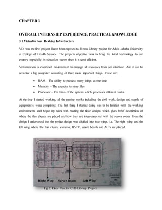
  • 1. CHAPTER 3 OVERALL INTERNSHIP EXPERIENCE, PRACTICALKNOWLEDGE 3.1 Virtualization Desktop Infrastructure VDI was the first project I have been exposed to. It was Library project for Addis Ababa University at College of Health Science. The projects objective was to bring the latest technology to our country especially in education sector since it is cost efficient. Virtualization is combined environment to manage all resources from one interface. And it can be seen like a big computer consisting of three main important things. These are:  RAM – The ability to process many things at one time.  Memory – The capacity to store files  Processor – The brain of the system which processes different tasks. At the time I started working, all the passive works including the civil work, design and supply of equipment’s were completed. The first thing I started doing was to be familiar with the working environments and began my work with reading the floor designs which gives brief description of where the thin clients are placed and how they are interconnected with the server room. From the design I understood that the project design was divided into two wings. i.e. The right wing and the left wing where the thin clients, cameras, IP-TV, smart boards and AC’s are placed. Right Wing Server Room Left Wing Fig 2. Floor Plan for CHS Library Project
  • 2. The first task given from my supervisor Mr.Abiy was to label thin clients with respect to their cablings from the patch panel inside the rack. It was that time when I learned to operate with Labeling machine. There were 350 thin clients which can be able to support the same number of students at one time. On my earlier working days, one thing I observed was that it need very great care to check the load checkup with power supply before starting up the electric power. It was great experience when I saw expert in electrical engineer came and check the load and capacity by using software. The first time the engineer from client side came and checked the power connectivity, he couldn’t verify that we were ready to start the server. He told us to change the power cable, which takes power from the Ethiopian Electric Power Corporation (EEPCo) to the Power Distribution Unit (PDU), from which the server takes power. Saying that it was insufficient to carry that much of power which the system requires. So, we changed the cable to newer one and it was good this time he came up to check and program the PDU. After that we were able to start the whole system to start with the active works. 3.2 Technical Details of VDI 3.2.1 How does VDI work? Virtualization is centralized desktop delivery solution. The concept of VDI is to store and run desktop workloads including a windows client operating system, applications, and data in a server based virtual machine (VM) in a data center and allow user to interact with the desktop presented onto a user via Remote Desktop Protocol (RDP). With VDI, a virtual desktop is isolated from the client’s device and runs in a VM maintained in a data center. Here, the device can be desktop, laptop or thin client. A VDI user interacts with one’s virtual desktop through RDP which provides a rich desktop experience. Similar to session-based remote desktops, VDI provides a server session with a full fidelity desktop environment that is virtualized within a server-based hypervisor. The premise on VDI is that all users are running virtual desktops on VM’s. The key technical components making a VDI reality include:  Windows Server 2012 R2 with Hyper-V: A virtualization host which runs VM’s and is essentially a grid in the virtualization solution infrastructure.
  • 3.  Microsoft Application Virtualization: A dynamic application deployment vehicle based on user profiles and transparent to local operating system  Microsoft Remote Desktop Services: A single and consistent URL for accessing resources published in multiple RDSHs and terminal servers  System Center Management Suite with Virtual Machine Manager (SCVMM): is a comprehensive management solution for managing enterprise IT life cycle. And it simplifies the deployment, provisioning and management of virtualization hosts and VM’s. In VDI deployment, there are two models:  In Static mode, there is one-to-one mapping of VM’s to users. Each user is assigned with a designated VM. Since VM’s are commonly stored on a Storage Area Network (SAN) and execute on a server, a larger number of users will likely to significant SAN requirements.  In a Dynamic architecture, on the other hand, there is only one master image of the desktop stored. All user personalization, profile, applications, etc. are stored separately from desktop, a VM cloned from the master image is combined with the user’s personal data and applications dynamically delivered to the user device based on roaming profiles. This delivers a personalized desktop experience by dynamically provisioning a base image. It simplifies the overall VM management by reducing the number of desktop images maintained. For the library project at college of health science at Addis Ababa University, we deployed the dynamic mode since the students do not sit on the same spot every time they come to the library. So, they will be authenticated before login to their account. This enables all students the personalized desktop experience to store their files on their VM. 3.2.2 Considerations for VDI solution:  Infrastructure with hypervisor hosts  Virtual machine management  Application Provisioning  Connection Management  Image management
  • 4.  Licensing 3.3 Power Unit the VDI uses 3 phase wire which came from Ethiopian Electric Power Corporation. The Power goes to the PDU through breakers mounted. all equipment's use the uninterruptible power supply since they can be easily damaged if we supplied them with under rated or over rated power. There is load balancing for the power supply. And the power distribution unit capacity was 169KVA, which will be only about 20% to be used by the system. So, it’s enough to supply the power required by all devices inside the server room and thin clients used by end users. The PDU consists of battery to store power in case the power is down from the line, so that the service won’t be disrupted, and no machine fails due to the power fluctuations. Since the power usage of the project is centralized in the server room, it produces much heat. So, it requires cooling system. That’s why air conditioners needed to be automatic. And since the project is deployed for medical students in the library, it is required that the hot air to be sucked out and recycled to environment by taking in cool air which creates good environment and make the students to effectively study there. That’s why it’s used LG – Inverters which is the best air conditioners in the market. 3.4 Servers 3.4.1 Dell M1000e This VDI project used Dell M1000e dell blade enclosure. The Dell PowerEdge M1000e Modular Blade Enclosure is the rock-solid foundation for Dell’s blade server architecture, providing an extremely reliable, flexible and efficient platform for building any IT infrastructure. The M1000e enclosure is built from the ground up to combat data center sprawl and IT complexity, delivering one of the most energy efficient, flexible and manageable blade server implementations on the market. The system can include up to 16 half-height blades (server modules), eight full-height blades, or a mixture of the two blade types. To function as a system, a blade is inserted into a Dell PowerEdge M1000e enclosure (chassis) that supports power supplies, fan modules, a Chassis Management Controller (CMC) module, and at least one I/O module for external network connectivity. The
  • 5. power supplies, fans, CMC, optional iKVM module, and I/O modules are shared resources of the blades in the enclosure. Enclosure represents an evolution of the entire rack-mounted infrastructure consolidating and repackaging featured infrastructure elements-computing, storage, networking, and power into a single infrastructure in a box that accelerates data center integration and optimization. The Blade System enclosure infrastructure is adaptive and scalable. Dell also offered some Cisco Catalyst switches for this blade enclosure. Cisco offers a range of switches for blade -systems from the main vendors. An M1000e enclosure offers several ways for management. The M1000e offers ‘out of band’ management: a dedicated VLAN for management. The server has two-part network LAN. The storage and servers are connected through, Blade switch. File Servers are dedicated servers used to store end user’s files they have four cables from which two of the cables are used to connect to storage and the other two cables are used to give space to machines. The servers have two network cards to control the switches. There is back bone link between the two switches. Fig. 4 Front of M1000e Blade Enclosure Fig. 5 Back of Enclosure
  • 6. For management, there is Chassis Management Controller(CMC), used to manage server, networks and storage. And this Management is conducted by using Vmware hypervisor. The hypervisor takes too small size. Only about 300Mb’s. The hypervisor for management is vSphere. The CMC modules in the enclosure offer management ethernet and do not rely on network connections made via I/O switches inside the blade. In this project case, physically isolated LAN is created for management allowing management access to all enclosures even when the entire infrastructure is down. Each M1000e chassis can hold two CMC modules. 3.4.2 Power Edge M630 Inside the blade enclosure we used 7 of M630 blade servers which deliver the compute power the client demanding applications require. It is Designed for use with the PowerEdge M1000e blade enclosure, the M630 offers exceptional scalability in environments ranging from IT as a service providers and private clouds to remote and branch offices. Fig. 6 Blade Enclosure and Power Edge M630 Blade Enclosure M1000e Power Edge M630 Servers
  • 7. On the servers we used VMware ESXi, the industry leading, purpose built bare metal hypervisor. ESXi is installed directly onto physical server enabling it to be partitioned into multiple logical servers referred to as Virtual Machines. Virtual servers are hosted on physical server. The VMware ESXi acts as an Operating System. It creates a layer to give storage and allows to go to the network. In this project, we have 7 Virtual Machines. To present storage to windows, we use ESXi Software. 3.5 SCv2080 Storage System The other part of the VDI is Storage where data are going to be kept. The storage used here is block storage, which is an IP storage. The IP Storage is approach to use the IP over storage area network (SAN). There are duplicate of the storage just to back up the first memory in case it is failed or corrupted due to different reasons. The SCv2080 storage system provides the central processing capabilities for the Storage Center Operating System (OS) and management of RAID storage. The Storage Center OS generates alert messages for temperature, fan, drive, power, and storage controller conditions. Use the Dell Storage Client to view these alerts. The SCv2080 also has LED indicators that signify possible problems with the Storage Center. The storage system holds the physical drives that provide Fig. 7 Storage Center
  • 8. storage for the Storage Center. If additional storage is needed, the SCv2080 also supports a single SC180 expansion enclosure. To insert drives into storage center, there are certain steps to follow. Step 1: Open the drawer by opening drawer latches. Step 2: Unlock the key on the drive to be inserted as shown in Fig. 8 (a) Step 3: Hold the drive by the driver carrier and slide it most of the way into the slot. And Using both hands (thumbs and forefingers), apply downward pressure firmly and equally across the driver carrier as shown in Fig. 8 (b) Step 4: Close the drawer. a) Locate the two lock-release buttons situated midway along the runners on each side of the drawer. b) Press the lock-release buttons inward and use your body to push the drawer toward the chassis until the locks disengage. c) Place your hands on the front bezel and continue to push the drawer inward until the bezel is flush with the chassis and the front drawer locks engage like as in Fig. 8 (c) Fig. 8 Steps to insert drives a b c
  • 9. The Storage system comes with two redundant power supply units, five redundant cooling fans, and up to two redundant storage controllers. The storage controller contains multiple I/O ports that provide communication with front -end servers and back-end storage. iSCSI is an acronym for Internet small computer systems interface, an IP based storage networking standard for linking data storage facilities. It’s used as an initiator to facilitate storage to be controlled over distances. 3.6 Dell Compellent FS8600 The Dell Compellent FS8600 is uniquely suited to overcome the challenges presented by explosive file data growth and file sprawl. With the combination of the Dell Fluid File System’s (FluidFS) scale-out single namespace and Compellent Storage Center’s Data Progression and Dynamic Capacity, we can reduce management overhead as well as leverage the platform’s unique storage efficiencies and cost of ownership attributes while providing class-leading availability and data protection. To further enhance performance, the FS8600 leverages the strengths of the Dell Storage Center platform such as:  Automated tiering to keep frequently accessed data on high-performance drives, and move passive data to lower cost, capacity-optimized drives  Thin provisioning to provide on-demand allocation of blocks  Optimization for solid-state drives  Unified block and file management through Dell Storage Manager (DSM) During the implementation, we have used two of FS8600 as file servers with two controllers each. Only one is used at a time and the other one is used as back up. And there is back bone connectivity among the two controllers. 3.7 Physical Connectivity and Networking As mentioned earlier, the project has two wings which are known to be left wing and right wing as shown in Fig 3. below. Both wings have their own end devices and they have patch panels from which the devices are connected to the switches. The cables needed to be tested using the network
  • 10. tester, by plugging one end of tester to the patch panel and the other to its respective end device. If all signals sent cannot be received to the other end, we do maintenance with its respective color code and we re-punch the cables. Likewise, we checked and confirmed all network cables that they work properly. Fig 3. Right and left and wing racks Both wings are in their own respective racks, being connected to the server by fiber optic cables. The fiber cables are spliced and directly go to fiber patch panel. So, they can be connected to the switches. And the switches are trunked by fiber cables so that the speed of data transfer will be high. The wings take data from distribution switches. The connection for thin clients are made by using cat6 cables. On one end we used Keystone and on the other end, they are connected to patch panels which are connected to the switches using RG-45 patch cords. To connect the cisco router and the distribution switch, the use of transceiver module was necessary for the fiber cables. 42 U 2 U 2 U 2 U 2 U 2 U 2 U 2 U 2 U 2 U 2 U 2 U 2 U Right Wing Rack 42 U 2 U 2 U 2 U 2 U 2 U 2 U 2 U 2 U 2 U 2 U 2 U 2 U Left Wing RackPower Strip Switches Patch Panels 1 U 1 U
  • 11. 3.7.1 CISCO Catalyst 3850 The Catalyst 3850-12S switch is used at distribution layer to aggregate the data received from the access layer switches before it is transmitted to the core layer for routing to its final destination. The switch controls the flow of network traffic using policies and delineates broadcast domains by performing routing functions between virtual LANs (VLANs) defined at the access layer. VLANs allow to segment the traffic on a switch into separate subnetworks. For example, in a university where we deployed the project, it might be required to separate traffic according to faculty, students, and guests. Distribution layer switches are typically high-performance devices that have high availability and redundancy to ensure reliability. Those switches are Ethernet switches to which you can connect devices such as Cisco, IP Phones, Cisco Wireless Access Points, workstations, and other network devices such as servers, routers, and other switches. The switch supports one hot-swappable network module that provides uplink ports to connect to other devices. The switch should only be operated with either a network module or a blank module installed. For the VDI project at the one of wing to connect to the core network we have used blank module installed because we had no uplink ports. 3.7.2 CISCO Catalyst 2960 – X Series The Catalyst 2960 series switches enable entry-layer enterprise, medium-sized, and branch office networks to provide enhanced LAN services. The Catalyst 2960 series switches, Core
  • 12. shown in Figure below are appropriate for access layer implementations where access to power and space is limited. The Catalyst 2960 switches we have used offered us the following:  Multilayered switching  QoS features to support IP communications  Access control lists  Fast Ethernet and Gigabit Ethernet connectivity  Up to 48 ports The Cisco Catalyst 2960-X Series provide easy device onboarding, configuration, monitoring, and troubleshooting. These fully managed switches can provide advanced Layer 2 and Layer 3 features as well as optional Power over Ethernet Plus (PoE+) power. Designed for operational simplicity to lower total cost of ownership, they enable scalable, secure, and energy-efficient business operations with intelligent services. The switches deliver enhanced application visibility, network reliability, and network resiliency. An external redundant power supply option is supported on the Cisco Catalyst 2960-X Series Switches. These switches come with one fixed power supply and an option for an external redundant power supply [RPS]. Fig. 8 Cisco 2960 3.7.3 Dell N4032 Switch It provides a stacking feature that allows multiple switches to operate as a single unit. Any Ethernet port type on the front panel can be used in creating links, including 10GbaseT. Since we couldn’t find 10G switch supplied for us, we used these switches. A single switch in the stack (known as the Master switch) manages all the units in the stack using a single IP address, which allows the user to access every port in the stack from this one address. This IP address is copied from the Master to the Standby when the Standby is created. If for any
  • 13. reason the Master fails, the Standby takes over as Master keeping the IP address of the stack the same. This allows continuous management of the stack. 3.8 Configuration and Management 3.8.1 Switches configuration There are different configurations which were done on each device used. For example, for the switches there are a lot of configurations like,  Telnet  SSH  Enabling Password and secret  Spanning-tree  Dedicating VLAN’s  IP helper address  Trunking etc. 3.8.2 Surveillance Camera The cameras must be configured to properly work and record each activity. The cameras we used were all 360-degree view recorders. After they are properly mounted on the ceiling and the data wires are connected to the patch panels we can manage them and view each of the camera. At the time our supervisor Mr. Abiy gave us task to configure camera, with my friends, first we identified which ports are connected to the camera. Then Abiy told us to install Axis IP software, because that was the software which can identify the cameras and displays their IP by filtering their MAC addresses. But one challenge we faced was the power which the switch gave to the cameras was not enough. So, we needed to add Axis PoE devices for each of the camera to give additional power. The storage spaces for the cameras are dedicated to them from the main storage center. And they are given the best quality of image by adjusting it from the settings. Another important thing in the configuration of the camera is to protect them from unauthorized access. In this case there are three levels of access. i.e Administrator, Viewer, and Guest each with different privilege.
  • 14. 3.8.3 Configuration steps for thin clients Two connection servers are created for both wings using Vmware connection server. Those connection servers are used for end users. To connect all thin clients to the connection server, the clients must join domain created by the server. There are certain configurations we did on the thin clients. Step 1: Check all connectivity of thin clients and monitor, i.e. Power cables, HDMI cable, keyboard, mouse and patch cord that they are correctly plugged and power them on. Step 2: Change the computer name so that it can be easily traced back in case it needs maintenance by going to System properties. For example: RW-P6-D10 means the PC is on right wing, patch panel number 6 and its on section D-10. Step 3: Join thin clients to be member of Domain. Then login with domain admin. Step 4: Protect the local disk, uninstall other software’s which came with thin clients by default. Step 5: Update VMware client software to 6.5 version. Step 6: Change the wallpaper to designed AAU logo by removing the old one from the root folder. Step 7: Create Connection Server on all clients, i.e. we created two connections, and make sure they are secured by checking the SSL security. This mode determines how the clients proceeds when it cannot verify that our connection to the server is not secure. Step 8: Finally protect all thin clients and only activate user mode. 3.9 Managing and Administering The name and identity of each students are added, managed and authenticated by using Active directory software. Its great software which has good security. The students can be grouped to easily manage them. And we got the names from the college of health science registrar and they were written in Microsoft excel software. The file format the active directory use is .vcf . so, we converted it. And gave the names to the software to authenticate each user. So, at the first time the student came, he is given default password and he will be prompted to change the default password, then after he confirms, he will be successfully logged in. The next time he come he is expected to
  • 15. enter the new password to login. Their files are redirected to the server so at any time the students came, they will get their files back. 3.9.1 Storage Center Management The whole storage system can be controlled from one interface. Even remotely, the administrator can check which part is failed without going to the server room. For example, To determine which hard drive failed, use the Dell Storage Client Software. Step 1: Click the Hardware tab. Step 2: In the Hardware tab navigation pane, select and expand the failed storage system. Step 3: In the Hardware Alerts area, find the hardware alert that identifies the enclosure with the failed hard drive. Fig. 9 Managing the hard drives
  • 16. 3.10 Data Center enhancement and Fire detection & suppression system at Zemen Bank This was my second project I participated during my internship time. The first time we went to the main data center, it was required to get authenticated before entering the server room since critical files of the bank are stored there. The first task we did there was, to mount new rack for backup system with new tape drives to store their files. There are different components used for the new backup system. And the data will be redirected to the drives through fiber optic cables. After we successfully mounted the components according to the design, since the devices were brought from dell company, and IPCOM partnered with them, they give technical support during the implementation of the project. Accordingly, Mr. James from Kenya came to configure the new backup system. Dell provides full guarantee and servicing for three years. Fig.10 The new backup system
  • 17. The next work we did at Zemen bank was to enhance the existing system they were using. This includes to redesign the whole data center to improve their system since the bank system needs to update its technology and their services. Being as an electrical engineer, it was really upsetting to see how the cables are managed inside the server room. Even if just simple problem was there, one cannot identify which cable is what and the technical experts need to trace back all cables one by one to see what the problem was. That is very annoying task and if one made mistake, the whole system may fail to work. Even power cables, data cables, and telephone lines are all assorted with one another and it was untechnical for such big company to work like that. Inside the main server rack which holds of different switches and routers, we consulted the technical officers to help us identify the cables. After that we identified all cables one by one by tracing back all of them. And in the documentation, number of ports on the patch panel and where each cable is connected to are identified too. It was very tiresome task to find each cable and it took us many days. For further improvement, new small rack which consists of patch panel and switch is introduced for employees on that floor. Then we identified all employee’s connection and redirected them to the new rack. This simplified our work. The other consideration for this enhancement project was to mount new air conditioner to cool the room temperature to required level by sucking out hot air from the room and taking in cool air to the server room. There was existing two AC’s since new server is added, it was expected to add new AC. One challenge we faced was that our client Zemen bank is expected to give service 24/7 and unless at some time the service is down, we couldn’t have done the implementation. So, we consulted with officers whom it concerns, and they agreed to down the service during Ethiopian Epiphany holiday. Until the service is down there being a lot of works to be done. Days before the holiday we identified all cables and managed them one by one. There was temperature sensor which displays the real time room temperature, but ICT operators are expected to go to server room every time they want to check it by passing all security layers successfully. Then, we placed the display out of server room by extending using cat6 wire. So, any time the staff want to check the room condition he can check it without entering the room.
  • 18. Fig. 10 a) Checking the power outlet b) Identifying wires During epiphany, we managed to implement the new design including new ceilings and addition of fire detection and suppression system. Environmental protection is most important thing in production environment like this. Fire prevention and building codes require that most new structures have some sort of fire protection system installed. Understanding how these systems operate is important for fire fighter safety and effective customer service. A fire detection system recognizes when a fire is occurring and activates the fire alarm system. It alert occupants and automatically activate fire suppression systems. The fire suppression system takes an oxygen from the environment which is one element in burning of things. At the midnight the service was down, and all racks are moved according to their designs. And new cable management is made onto all racks and new ceiling is made for the server room. Finally, after working the whole night, we finalized the whole work and powered on the service. During the operation, the team from HP company and ICT officers of Zemen bank was with us the whole night. Finally, the new look of the data center is impressive and attractive. In addition, all documentation is made for them, that will make further troubleshooting and enhancement of the server room to be simple and easy. The company finally told us that they are very interested by the service IPCOM did for them.
  • 19. 3.11 Project at Addis Ababa University, 6 kilo There are two projects at Addis Ababa university which I saw, The first one is Implementation of new modular data center for the new registrar and the second one is network and IPTV installation at presidential lobby. Though, the first one is still on progress I have actively participated on the later one. 3.11.1 Modular Datacenter A modular data center can be defined as more of an approach to data center design that incorporates contained units, many times in the form of prefabricated modules. The data center infrastructure has evolved far beyond a centralized solution. Now, with cloud computing, more data demands, and distributed environments — there is a greater than ever need for agility. In creating a more flexible data center solution, organizations are seeing the direct benefits in working with modular designs. A modular data center is an approach that implies a prefabricated module or a method for delivering data center infrastructure in a modular fashion. A modular solution takes the best ideas for design, reliability and efficiency and packages every-thing into a prefabricated, repeatable and operationally optimized module. Now data centers can grow and expand while using efficient modular technologies. Exploring the modular product and provider markets, as well as the benefits that a modular approach can provide will allow any company to better align their IT infrastructure with the needs of an evolving business environment. 3.11.2 IPTV IPTV is different, improved technology than “traditional” cable or satellite TV, and it allows for more flexibility within the network. IPTV enables two-way interactivity, versus a traditional one- way cable or satellite broadcast network. The two-way IPTV network means viewers have more options to interact, personalize and control their viewing experience, IP technology also allows for more flexibility within home network. With IPTV, it lets users to watch shows recorded from DVR on TV. It can also connect gaming consoles, laptops and other devices to home network using the ethernet port.
  • 20. At the presidential lobby, we used 16 LCD Tv’s each with 46 inches, grouped into 3. Which means, 4 screens are mounted together to display the same image. All LCD are wall mounted, so the first step was to build the frame to hold screens on the wall. The direction of connectivity of HDMI cable will be as the following image. The arrows represent the direction of the arrows represent to where the HDMI cable would be plugged in. One TV will be considered as a master to control all the other TV’s, in this case TV 3 is assumed to be the one. Fig.11 a) split tv design b) mounting TV’s (C) After mounting IPTV After properly aligning all tv’s by using mechanical parts of the support, its an easy task to configure all tv settings using their remote control. Even those tv’s can be connected to internet since we have punched RJ 45 cables at the back of those tv’s. They have also space to copy files from USB drives to store and play them. `3 1 2 4