1. Fuel Cell – A Future Powerhouse
Fuel Cell History
The principle of the fuel cell was discovered by German scientist Christian Friedrich
Schönbein in 1838. Based on this work, the first fuel cell was demonstrated by Sir William
Robert Grove in the February 1839. In 1955, W. Thomas Grubb, a chemist working for the
General Electric Company (GE), further modified the original fuel cell design. Three years
later another GE chemist, Leonard Niedrach, devised the 'Grubb-Niedrach fuel cell'. GE went
on to develop this technology with NASA and McDonnell Aircraft, leading to its use during
Project Gemini. This was the first commercial use of a fuel cell. It wasn't until 1959 that
British engineer Francis Thomas Bacon successfully developed a 5 kW stationary fuel cell. In
1959, a team led by Harry Ihrig built a 15 kW fuel cell tractor for Allis-Chalmers which was
demonstrated across the US at state fairs. This system used potassium hydroxide as the
electrolyte and compressed hydrogen and oxygen as the reactants. Later in 1959, Bacon
and his colleagues demonstrated a practical 5 kW unit capable of powering a welding
machine. In the 1960s, Pratt and Whitney licensed Bacon's U.S. patents for use in the U.S.
space program to supply electricity and drinking water (hydrogen and oxygen being readily
available from the spacecraft tanks). United Technologies Corporation's UTC Power
subsidiary was the first company to manufacture and commercialize a large, stationary fuel
cell system for use as a co-generation power plant in hospitals, universities and large office
buildings. UTC Power continues to be the sole supplier of fuel cells to NASA for use in space
vehicles, having supplied the Apollo missions, and currently the Space Shuttle program, and
is developing fuel cells for automobiles, buses, and cell phone towers; the company has
demonstrated the first fuel cell capable of starting under freezing conditions with its proton
exchange membrane automotive fuel cell.
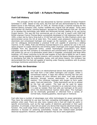
Fuel Cells: An Overview
A fuel cell is an electrochemical device that produces electricity
and heat from a fuel (often hydrogen) and oxygen. Unlike a
conventional engine, it does this without burning the fuel and
can therefore be more efficient and clean. Fuel cells produce
electricity through reverse electrolysis, an electrochemical
reaction. This combines hydrogen and oxygen to form water
vapor, heat and electricity. These byproducts can be re-utilized
by the fuel cell system. The heat can be used for space
heating. The electricity is directed to an external circuit, where
it is used as needed. Most fuel cells use hydrogen at the point
where the electrochemical reaction takes place. This hydrogen
can be chemically generated or reformed from a variety of
normal fuels, including gasoline, natural gas or methanol.
Fuel cells have a number of advantages over other technologies for power generation.
They have the potential to use less fuel than competing technologies and to emit no
pollution when used. There are also many reasons why a fuel cell might be useful in
specific environments, such as the high quality of electricity generated or their quiet
operation. In principle, a fuel cell can power any device that requires electrical energy to
function. This could range from a mobile phone to a factory. Presently, the majority of
attention is focused on powering automobiles, houses and medium-sized portable
electrical equipment. However, portable computers may be an early application.
2. Typical fuel cell systems cost US$1000 per kilowatt of electric power output. In 2008,
the US Department of Energy reported that fuel cell system costs in volume production
are $73 per kilowatt. The goal is $35 per kilowatt.
There are four main types. They are distinguished by the electrolyte used. The types of fuel
cells are: polymer electrolyte membrane or proton exchange membrane (PEM); molten
carbonate (MCFC); phosphoric acid (PAFC); and, the solid oxide fuel cell (SOFC). Fuel Cells
achieve high fuel efficiencies and produce extremely low emissions. Fuel cells can operate
on a wide variety of fuels. Moreover, since they utilize electrochemical reactions for power
production, they contain no moving parts. These features make them simple to operate,
quiet and very reliable.
In the near future, fuel cells will play an increasing role in everyday life. Soon fuel cell
powered cars and trucks will be running in the streets towns emitting nothing more than
harmless water vapor. Fuel cells will find their way into cell phones and laptop computers
whose battery life is measured in days instead of hours. A house or office will have a fuel
cell that replaces a conventional furnace, providing heat and electricity free from the
disruptions associated with the utility's electric grid. Most of the companies planning to
manufacture fuel cells are still in the research and development stage of production.
Eventually fuel cells can be expected to replace grid power. The current configurations of
the fuel cell systems will not support grid independent, primary power operation for
prolonged periods of time.
Basic Physics of Fuel Cells
The conventional conversion of the chemical energy of a fuel into electricity is
currently based on the application of heat engines. These machines work according to the
principle of indirect energy conversion: first of all, heat must be produced which is then
converted into mechanical and finally into electric energy. The theoretical energetic
efficiency ηc
max is determined by an overall process characterized by the Carnot factor:
The inlet temperature T1 of the working
medium is higher than the outlet
temperature T2, their difference
corresponding to the deviation of the
value ηc
max from the maximum quantity 1
(100%). This Carnot efficiency is
characteristic of all energy converters such
as steam turbine, internal combustion
engine, thermoionic converter etc. which
work between a source and a sink
temperature. The energy yield in a real
system is always lower than indicated by
the corresponding Carnot factor and
ranges in most cases between 30 and 40
per cent, for today's highly developed combined cycle plants between 55 and 60 %. The
latter, however, are only available in a very high power range and cannot be used, for
ηc
max
= -------------------- = --------- x 100%
Produced Energy
Heat Input
T1
– T2
T1
3. example, for small or mobile (cars) systems. The cause for the reduction in energetic
efficiency is here energy losses at the different stages of the conversion process. The fuel
cell competes with conventional thermo-mechanical energy conversion.
The fuel cell is an electrochemical device for the direct conversion of the chemical energy of
a fuel into electricity. Similar to batteries, fuel cells produce low-voltage direct current. A
battery or an accumulator consumes a chemical substance contained in the cell stack itself
for electricity production. In fuel cells, however, the fuels are continuously fed to the cell
stack similarly to an internal combustion engine. The energetic conversion rate in a fuel cell
is given by the relation.
The value ∆H represents the corresponding enthalpy change of the combustion reaction. In
contrast to normal thermal combustion, however, in which the total reaction enthalpy ∆H is
converted into heat, in a fuel cell only the energetic fraction ∆G (free reaction enthalpy) is
directly converted into electricity, i.e. the maximum theoretical efficiency ηBZ
max is given by
the formula
where ∆GT is the value of the free reaction enthalpy at the cell operating temperature TZ and
∆H0
is the standard value of the reaction enthalpy. The relation between ∆G and ∆H is
known to be
∆G = ∆H - T ∆S
Hence follows the efficiency of the fuel cell as
Depending on the sign of the reaction entropy ∆S, the efficiency may be smaller, equal to or
even higher than 100 %. In the latter case, heat is extracted from the environment. The
fuel cell directly supplies electric current of the theoretical d.c. voltage (Erev)
The most important fuel cell reaction is the combustion reaction of hydrogen
2H2 + O2 2H2O
At a pressure of 1 bar and a temperature of 25°C the corresponding d.c. voltage for this
reaction is 1.229 volt. This voltage is a function of temperature, i.e. the same also applies to
the efficiency.
ηBZ
= -------------------- x 100%
Produced Energy
∆H
ηBZ
max
= ------ x 100%
∆GT
∆H0
ηBZ
max
= ------------ x 100%
∆H - T ∆S
∆H
ηBZ
max
= [ 1 - ------ ] x 100%
T∆S
∆H
Erev
= -------
-∆G
nF
4. Operating principle of the fuel cell
A fuel cell consists of the fuel electrode (anode) and the oxygen electrode (cathode),
which are interconnected by an ion-conducting electrolyte. The electrodes are electrically
coupled to an electricity consumer (for example an electric motor) by external metallic lines
outside the cell. In this section of the electric circuit, the electric current is transmitted by
the electrons whereas in the electrolyte the current transfer is made by means of ions. At
low temperatures, these may be protons in acidic electrolytes whereas hydroxyl ions are
predominantly involved in alkaline electrolytes. In a higher temperature range in the so-
called solid oxide fuel cells, which operate between 600°C und 1000°C, , the ionic
conduction is either realized by the CO2-
3 carbonate ions or the negatively charged O2-
oxide
ions. In the most common fuel cell, the anode is supplied with hydrogen as the fuel gas
which is electrochemically split into protons and electrons at the electrode/electrolyte
interface. The electrons which perform electrical work in the outer electric circuit are passed
into the cathode where they reduce the oxygen into water at the electrode/electrolyte
interface.
The required protons come from the anode through
the electrolyte. The electrodes must also be
permeable to gas, i.e. porous. A fuel cell reaction
normally requires all three phases to be present:
the solid phase (electron conductor), the liquid
phase (ion conductor) and the gas phase (electrode
pores). In the fuel cells with liquid electrolyte,
which operate below the boiling point of water, an
electrolyte circulation system with external water
removal (e.g. evaporation) should be present. In
fuel cells operating with a solid electrolyte, at
higher temperature, the water formed is directly passed from the electrolyte into the
cathodic gas compartment and removed there.
The above thermodynamic relations
indicate the maximum possible energy
which a fuel cell can supply. During
operation, however, the cells have
energetic losses which may have
different causes. They may either be
caused by the kinetics of the electrode
reactions or are given by the structure
of the cell or the type of process
control. In principle, the fuel cells can
utilize all fluids capable of oxidation. In
practice, hydrogen is used almost
exclusively as the fuel in current low-
temperature cells. This is due to the
high electrochemical activity of
hydrogen in comparison to all other
fuels such as hydrocarbons, alcohols or products of coal gasification. Its electrochemical
reaction mechanism is characterized by the simplicity of the individual reaction steps in
which no inhibiting by-products arise. In this respect, hydrogen is superior to the
carbonaceous fuels. Below a temperature of about 300°C, carbonaceous fuels are not only
electrochemically slow-reacting but generally also lead to the formation of by-products
5. which may act as catalyst poisons on the electrodes. From economical aspects, however,
the use of hydrocarbons as the fuel is being attached much greater significance. Since the
oxidation rates of carbonaceous fuels are only satisfactory in technical terms at elevated
temperatures, intensive work has recently also been performed on the development of
medium- to high-temperature fuel cells. Many operating data of fuel cell systems have been
extensively tested especially in the USA and Japan.
Different Types of Fuel Cells
Fuel cell technology has been developed and improved dramatically in the past few
years, and this has once again captured both the public's and industry's attention
concerning the prospect of fuel cells as practical power sources for terrestrial applications.
At present, fuel cell technology is being routinely used in many specific areas, notably in
space explorations, where fuel cell operates on pure hydrogen and oxygen with over 70%
efficiency with drinkable water as the only by-product. There are now approximately over
200 fuel cell units for terrestrial applications operating in 15 countries. Impressive technical
progress has been achieved in terms of higher power density and better performance as
well as reduced capital and maintenance and operation cost; this is driving the development
of competitively priced fuel cell-based power generation systems with advanced features for
terrestrial use, such as utility power plants and zero-emission vehicles. In view of
decreasing fossil-fuel reserves and increasing energy demands worldwide, fuel cells will
probably become one of the major energy technologies with fierce international competition
in the twenty-first century.
The major terrestrial commercial applications of fuel cells are electric power generation in
the utility industry, and as a zero-emission power train in the transportation sector. For
these practical applications, the efficiencies of fuel cells range some where between 40%
and 65%. Typically, the cell electric potential is only about 1 V across a single cell, and it
decreases due to various loss mechanisms under operational conditions. Thus, multiple cells
are required to be connected together in electrical series to achieve a useful voltage for
practical purposes, and these connected cells are often referred to as a fuel cell stack. A fuel
cell system consists of one or multiple fuel cell stacks connected in series and/or parallel,
and the necessary auxiliaries whose composition depends on the type of fuel cells and the
kind of primary fuels used. The major accessories include thermal management (or cooling)
subsystem, fuel supply, storage and processing subsystem, and oxidant (typically air)
supply and conditioning subsystem.
A summary of the state-of-the-art technology for the six major types of fuel cells is
presented, including
• Alkaline fuel cells (AFCs)
• Polymer-electrolyte-membrane fuel cells (PEMFCs)
• Direct-methanol fuel cells (DMFCs)
• Phosphoric-acid fuel cells (PAFCs)
• Molten-carbonate fuel cells (MCFCs)
• Solid-oxide fuel cells (SOFCs)
Five of these are classified based on their electrolytes used, including the alkaline,
phosphoric-acid, polymer-electrolyte-membrane, molten-carbonate, and solid-oxide fuel
6. cell. The direct-methanol fuel cell is classified based on the fuel used for electricity
generation.
Alkaline fuel cells
Alkaline fuel cells (AFCs) give the best performance among all the fuel cell types
under the same or similar operating conditions when running on pure hydrogen and oxygen.
Hence, they are among the first fuel cells to have been studied and taken into development
for practical applications especially in space programs. Each shuttle flight contains a 36-kW
AFC power system. Its purchase price is about US$28.5 million, and it costs NASA an
additional $12-19 million annually for operation and maintenance. Although the
manufacturer claims about 2400 h of lifetime, NASA's experience indicates that the real
lifetime is only about 1200 h. With sufficient technology development, 10,000 h are
expected as the life potential (or upper limit) for the AFC system. The typical working
temperature of AFC power systems aimed at commercial and terrestrial applications ranges
from 20 to 90°C, and the electrolyte is a KOH solution (30-35%).
The major technical challenge is that alkaline electrolytes, like potassium or sodium
hydroxide, do not reject carbon dioxide, even the 300 - 350 ppm of carbon dioxide in
atmospheric air is not tolerated (carbon dioxide concentration in both cathode and anode
gases must be less than 10- 100 ppm by volume). Terrestrial applications almost invariably
require the use of atmospheric air as oxidant due to technical and economic considerations.
A price of about US$400-500/kW has been quoted using today's technologies and today's
knowledge in large-scale production. However, small-scale commercial production cost is
estimated to be 5-10 times higher.
Polymer-Electrolyte-Membrane Fuel Cells
The polymer-electrolyte-membrane fuel cells (PEMFC) are also called solid-polymer
(electrolyte) fuel cell or proton exchange membrane fuel cell. It was the first type of fuel cell
that was put into practical application in the Gemini space missions from 1962 to 1966. It
consists of a solid polymeric membrane acting as the electrolyte. The solid membrane is an
excellent proton conductor, sandwiched between two platinum catalyzed porous carbon
electrodes. It has fast-start capability and yields the highest output power density among all
types of the fuel cells. It has no volatile electrolyte and has minimal corrosion concerns. It
has truly zero pollutant emissions with potable liquid product water when hydrogen is used
as fuel. As a result, the PEMFC is particularly suited for vehicular power applications.
Because of the limitation imposed by the membrane and problems with water balance, the
operating temperature of PEMFCs is usually less than 120°C, typically 80°C.
The polymer-electrolyte-membrane (PEM) is essentially an acid electrolyte. The PEM fuel cell
requires hydrogen gas as the fuel, and oxygen (typically air) as the oxidant. The half-cell
reactions are:
At the anode : H2 2H+
+ 2e-
At the cathode : ½ O2 + 2H+
+ 2e-
H2O
Overall cell reaction : H2 + ½ O2 H2O + Heat +Electricity
7. The current PEMFCs use perfluorinated sulfonic acid membrane (almost exclusively Nafion
from DuPont) as the proton-conducting electrolyte, carbon paper or cloth as the anode and
cathode backing layers, and platinum or its alloys, either pure or supported on carbon black,
as the catalyst. The PEMFCs usually operate at about 80°C and 1-8 atm pressure. Operation
at high pressure is necessary to attain high power densities, particularly when air is chosen
as the cathodic reactant.
As an acid-electrolyte fuel cell operating at low temperature, the PEMFC is primarily
vulnerable to carbon monoxide poisoning. Even a trace amount of CO drastically reduces the
performance levels, although CO poisoning effect is reversible and does not cause
permanent damages to the PEMFC system.
For practical applications, PEMFC performance in terms of energy efficiency, power density
(both size and weight) and capital cost must be further improved. PEMFCs have achieved a
high power density of over 1 kW /kg and 0.7 kW /L, perhaps the highest among all types of
the fuel cells currently under development. It is also projected that the power density may
be further improved, up to 2-3 kW/L, with unitized metallic (stainless steel) bipolar plates.
The capital cost has been estimated to vary from the most optimistic of $1,500/kW to the
most pessimistic of $50,000/kW at the current technology, and is projected to reach
approximately $200-$300/kW, assuming a 1O-20-fold reduction in the membrane and
catalyst cost and also considering mass production. A target of $30/kW has been set for
PEMFC power unit running on pure hydrogen for transportation applications. It is expected
that PEMFC technology is about five to ten years from commercialization. However,
application of PEMFCs in powering portable and mobile electronics such as laptops has
already begun.
Currently, they are considered the best choice for zero-emission vehicles as far as present-
day-available fuel cell technologies are concerned. Their high power density and small size
make them primary candidates for light-duty vehicles. In addition, NASA is conducting a
feasibility study of using the PEMFC power systems for its space programs (mainly space
shuttle missions) in place of its current three 12 kW AFC power modules.
Direct-Methanol Fuel Cells
All the fuel cells for commercial applications require the use of gaseous hydrogen
directly or methanol, reformed to hydrogen as the fuel. Pure oxygen or oxygen in air is used
as the oxidant. The use of gaseous hydrogen as a fuel presents a number of practical
problems, such as storage system weight and volume, as well as handling and safety issues.
The low volumetric energy density of hydrogen also limits the distance between vehicle
refueling. Methanol as a fuel offers ease of handling and storage, and potential
infrastructure capability for distribution. Methanol also has a higher theoretical energy
density than hydrogen (5 kWh/L compared with 2.6 kWh/L for liquid hydrogen). Therefore,
direct oxidation of methanol is an attractive alternative in view of its simplicity from a
system point of view. The direct-methanol fuel cells utilizing proton-exchange membrane
(PEM) have the capability of efficient heat removal and thermal control through the
circulating liquid, and elimination of humidification required to avoid membrane dryout.
8. The direct-methanol fuel cell allows the direct use of an aqueous, low-concentration (3%),
liquid methanol solution as the fuel. Air is the oxidant. The methanol and water react
directly in the anode chamber of the fuel cell to produce carbon dioxide and protons that
permeate the PEM and react with the oxygen at the cathode. The half-cell reactions are:
Anode: CH3OH + H2O CO2 + 6H+
+ 6e-
Cathode: 6H+
+ 6e-
+ 3/2 O2 3H2O
Net cell reaction: CH3OH + 3/2 O2 CO2 + 2H2O
Because a PEM (typically Nafion 117) is used as the electrolyte, the cell operating
temperature must be less than the water boiling temperature to prevent dryout of the
membrane. Typically, the operating temperature is around 90°C, and the operating
pressure ranges from one to several atmospheres. The state-of-the-art performance is an
energy conversion efficiency of 34% (from methanol to electricity) at 90°C using 20 psig air,
at a cell voltage of 0.5 V.
The system is extremely sensitive to carbon monoxide (CO) and hydrogen sulfide (H2S).
Carbon monoxide may exist as one of the reaction intermediaries, and can poison the
catalyst. Sulfur may be present if methanol is made from petroleum oils, and needs to be
removed. Because the electrolyte in DMFCs is essentially acid, expensive precious metals
(typically platinum or its alloys) are used as the catalyst.
The DMFC power system is under-developed, and until now no one could demonstrate any
feasibility for commercialization. It remains at a scale of small demonstration in the sub-kW
range. It is said that one company in the world has recently been formed to explore the
potential of the DMFC systems, and to develop DMFC for transportation applications.
However, the DMFC system is at least ten years away from any realistic practical
applications, judging from the progress of other types of fuel cells in the past.
DMFCs offer the potential for high power density and cold-start capabilities. As a result,
DMFCs have a great potential for transportation applications ranging from automobiles,
trains and ships, etc. For utility applications, small DMFCs units have potential for use in
residential and office buildings, hotels and hospitals, etc. for the combined electricity and
heat supply (cogeneration). Because methanol can be made from agricultural products, the
use of methanol is also compatible with renewable energy sources to allow for sustainable
development.
Phosphoric-Acid Fuel Cells
The phosphoric-acid fuel cell (PAFC) is the most advanced type of fuel cell and is
considered to be "technically mature" and ready for commercialization after nearly 30 years
of R&D and over half a billion dollars expenditure. Therefore, the PAFC has been referred to
as the first-generation fuel cell technology.
The basic components of a phosphoric-acid fuel cell are the electrodes consisting of finely
dispersed platinum catalyst or carbon paper, SiC matrix holding the phosphoric acid, and a
bipolar graphite plate with flow channels for fuel and oxidant. The operating temperature
ranges between 160°C-220°C; and pressure as high as 8 atm. are required for satisfactory
performance. It can use either hydrogen or hydrogen produced from hydrocarbons (typically
9. natural gas) or alcohols as the anodic reactant. The waste heat can also be used for space
heating and hot water supply. However, the PAFC cannot tolerate the presence of carbon
monoxide and H2S, which are commonly present in the reformed fuels. These contaminants
poison the catalyst and decrease its electrochemical catalytic activity. Carbon monoxide
level must be less than 200-300 ppm.
The PAFC system is the most advanced fuel cell system for terrestrial applications. Its major
use is in on-site integrated energy systems to provide electrical power in apartments,
shopping centers, office buildings, hotels, and hospitals, etc. These fuel cells are
commercially available in the range from 24 V, 250-W portable units to 200-kW on-site
generators. PAFC systems of 0.5-1.0 MW are being developed for use in stationary power
plants of 1-11 MW capacity. The most advanced PAFC system costs about US$3,000/kW
(the best technology possible for the PAFCs), whereas the conventional thermal power
generation system costs only about US$l,OOO/kW.
Molten-Carbonate Fuel Cells
The molten-carbonate fuel cell (MCFC) is often referred to as the second-generation
fuel cell because its commercialization is normally expected after the PAFC. It is believed
that the development and technical maturity of the MCFC is about 5-7 years behind the
PAFC. At present, the MCFC has reached the early demonstration stage of pre-commercial
stacks, marking the transition from fundamental and applied R&D towards product
development.
The MCFC operates at high temperature. The operating temperature of the MCFC is
generally around 600-700°C, typically 650°C. Such high temperatures produce high-grade
waste heat that is suitable for fuel processing, cogeneration, or combined cycle operation,
leading to higher electric efficiency. It also yields the possibility of utilizing carbonaceous
fuels (especially natural gas) directly, through internal reforming to produce the fuel
(hydrogen) ultimately used by the fuel cell electrochemical reactions. It has been estimated
that the MCFC can achieve an energy conversion efficiency of 52-60% (from chemical
energy to electrical energy) with internal reforming and natural gas as the primary fuel.
Some studies have indicated that the MCFC efficiency of methane to electricity conversion is
the highest attainable by any fuel cell or other single pass/simple cycle generation scheme.
A MCFC consists of two porous gas-diffusion electrodes (anode and cathode), and a
carbonate electrolyte in liquid form. The electrochemical reaction occurring at the anode and
the cathode is:
Anode: H2 + CO3
--
H2O + CO2 + 2e-
Cathode: ½ O2 + CO2 + 2e-
CO3
--
Net cell reaction is: H2 + ½ O2 H2O
The MCFCs use a molten alkali carbonate mixture as the electrolyte, which is immobilized in
a porous lithium aluminate matrix. The conducting species is carbonate ions. Lithiated nickel
oxide is the material of the current choice for the cathode, and nickel, cobalt and copper are
currently used as anode materials, often in the form of powdered alloys and composites with
oxides. MCFCs normally have about 75-80% fuel (hydrogen) utilization. MCFCs do not suffer
10. from carbon monoxide poisoning; in fact, they can utilize carbon monoxide in the anode gas
as the fuel. However, they are extremely sensitive to the presence of sulfur (< 1 ppm) in
the reformed fuel (as hydrogen sulfide, H2S) and oxidant gas stream (SO2 in the recycled
anode exhaust).
MCFC technology is in the first demonstration phase, and under the product development
with full-scale systems at the 250 kW to 2 MW range. The short-term goal is to reach a
lifetime of 25,000 h, and the ultimate target is 40,000 h. It is estimated that the capital cost
is about US$1000-1600/kW for the MCFC power systems. The cost breakdown is, at full
scale production levels, about 1/3 for the stack, and 2/3 for the balance of the plant. It is
also generally accepted that the cost of raw materials will constitute about 80% of total
stack costs. Although substantial development efforts supported by fundamental research
are still needed, the available knowledge and number of alternatives will probably make it
possible to produce pre-commercial units in the earlier part of the coming decade at a
capital cost of US$ 2000-4000/kW. Pre-competitive commercial units may be expected
some years later by which time further cost reduction to full competitiveness will be guided
by extensive operating experience and increased volume production. The MCFC is being
developed for their potential as baseload utility generators. However, their best application
is in distributed power generation and cogeneration (i.e., for capacities less than 20 MW in
size), and in this size range MCFCs are 50%-100% more efficient than turbines- the
conventional power generator.
Solid-Oxide Fuel Cells:
Solid-oxide fuel cells (SOFC) have emerged as a serious alternative high-
temperature fuel cell, and they have been often referred to as the third-generation fuel cell
technology because their commercialization is expected after the PAFCs (the first
generation) and MCFCs (the second generation).
SOFC is an all-solid-state power system, including the electrolyte, and it is operated at high
temperature of around 1000°C for adequate ionic and electronic conductivity of various cell
components. The all-solid-state cell composition makes the SOFC system simpler in
concept, design and construction; two-phase (gas-solid) contact for the reaction zone
reduces corrosion and eliminates all the problems associated with the liquid electrolyte
management. The high-temperature operation results in fast electrochemical kinetics (i.e.,
low activation polarization) and no need for noble-metal catalysts. The fuel may be gaseous
hydrogen, H2/CO mixture, or hydrocarbons because the high temperature operation makes
the internal in situ reforming of hydrocarbons with water vapor possible. It is specially
noticed that CO is no longer a contaminant; rather it becomes a fuel in SOFCs. More
importantly, the SOFC provides high-quality waste heat that can be utilized for cogeneration
applications or combined cycle operation for additional electric power generation. It has
been estimated that the chemical to electrical energy conversion efficiency is 50-60%, even
though some estimates go as high as 70%-80%.
As mentioned earlier, both hydrogen and carbon monoxide can be oxidized in the SOFCs
directly. Therefore, if hydrogen or hydrogen-rich gas mixture is used as fuel, and oxygen (or
air) is used as oxidant, the half cell reaction becomes:
Anode: H2 + O--
H2O + 2e-
Cathode: 2e-
+ ½ O2 O--
Overall cell reaction: H2 + ½ O2 H2O
11. However, if carbon monoxide is provided to the anode instead of hydrogen, the anode
reaction becomes:
Anode: CO + O--
+ CO2 + 2e-
Cathode: 2e-
+ ½ O2 O--
Net cell reaction: CO + ½ O2 CO2
The solid electrolyte in SOFCs is usually yittria-stabilized zirconia (YSZ), thus a high-
operating temperature of around 1000°C is required to ensure adequate ionic conductivity
and low ohmic resistance. This is especially important because the cell open-circuit voltage
is low, compared with low temperature fuel cells, typically around 0.9-1 V under the typical
working conditions of the SOFCs.
The key technical challenges are the development of suitable materials and the fabrication
techniques. Of the material requirements, the most important consideration is the matching
of the thermal expansion coefficients of electrode materials with that of the electrolyte to
prevent cracking or delamination of SOFC components either during high temperature
operation or heating/ cooling cycles. One of the remedies for the thermal expansion
mismatch is to increase the mechanical toughness of the cell materials by developing either
new materials or doping the existing materials with SrO and CaO. Another focus of the
current development is the intermediate temperature SOFCs operating at around 800°C a
lower for better matching with the bottoming turbine cycles and lessening requirements for
the cell component materials. Again appropriate materials with adequate electrical
conductivity are the key areas of the development effort, and thermal expansion matching
among the cell components is still necessary.
There are three major configurations for SOFCs: the tubular, flat plate, and monolithic. Even
though the SOFC technology is in the developmental stage, the tubular design has gone
through development since the late 1950s, and is now being demonstrated at user sites in a
complete operating fuel cell power unit of nominal 25 kW (40 kW maximum) capacity. The
present estimated capital cost is US$1,500/kW, but is expected to be reduced with
improvements in technology. Therefore, the SOFCs may become very competitive with the
existing technology for electric power generation. However, it is believed that the SOFC
technology is at least five to ten years away from commercialization.
SOFCs are very attractive in electrical utility and industrial applications. The high operating
temperature allows them to use hydrogen and carbon monoxide from natural-gas steam
reformers and coal gasification plants, a major advantage as far as fuel selection is
concerned. SOFCs are being developed for large (> 10 MW, especially 100-300 MW)
baseload stationary power plants with coal as the primary fuel. This is one of the most
lucrative markets for this type of fuel cells. A promising field for SOFCs is the decentralized
power supply in the MW range, where the SOFC gains interest due to its capability to
convert natural gas without external reforming. In the range of 1 to 10 MW, the predicted
benefits in electrical efficiency of SOFC-based power plants over conventional methods of
electricity generation from natural gas can only be achieved by an internal reforming SOFC.
Therefore, internal reforming is a major target of present worldwide SOFC development.
SOFCs are also being developed as auxiliary power for large transport trucks.
12. Summarized View
Table provides a summary of the operational characteristics and application of the six
major types of fuel cell.
Operational characteristics and technological status of various fuel cells
Type
of
Fuel
Cells
Operating
Temp. O
C
Power
Density
(mW/cm2
)
(Present)
Projected
Projected
Power
Level
(kW)
Fuel
Efficiency
Projected
Lifetime
(hours)
Projected
Capital
Cost
($/kW)
Areas of Application
AFC 60-90 (l00-200)
>300
10-
100
40-60 >10,000 >200 Space, mobile
PAFC
160-220 (200)
250
100-
5000
55 >40,000 >3,000 Dispersed &
distributed power
PEMFC
50-80 (350)
>600
0.01-
1000
45-60 >40,000 >200 Portable, mobile,
space, stationary
MCFC
600-700 (100)
>200
1000-
1,00,000
60-65 >40,000 1,000 Distributed power
generation
SOFC
800-1000 (240)
300
100-
1,00,000
55-65 > 40,000 1,500 Base load power
generation
DMFC 90 (230)
?
0.001-
100
34 >10,000 >200 Portable, mobile
Advantages of Fuel Cells
It has very high conversion efficiencies; as 70% have been observed since it is a direct
conversion process and does not involve a thermal process. In the conventional,
thermal process for generating electricity, heat energy produced by combustion of the
fuel is converted partially into mechanical energy in a steam turbine and then into
electricity by the means of a generator. The efficiency of heat energy is limited by
operating temperatures, and in the large modern steam-electric plants above 40% of
the heat energy of the fuel is converted into electrical energy. Fuel cells on the other
hand, are not heat engines and are not subjected to their temperature limitations.
Fuel cells can be installed near the use point, thus reducing electrical transmission
requirements and accompanying losses. Consequently considerably higher energy
efficiencies are possible.
They have few mechanical compliments; hence, they operate fairly quietly and require a
little attention and less maintenance
Atmospheric pollution is small if the primary energy source is hydrogen, the only waste
product water. If the source is a hydrocarbon such as combustion of fossil fuels, CO2 is
also produced. Some heat is generated by the fuel cell, but it can be dissipated to the
atmosphere or possibly used locally.
There is no requirement for large volumes of cooling water such are necessary to
condense exhaust system from a turbine in conventional power plant.
As fuel cells do not make noise, they can be readily accepted in the residential areas.
The fuel cell takes little time to go into operation.
The space requirement for fuel cell power plant is considerably less as compared to the
conventional power plants.
* The only disadvantages of the fuel cells are their high initial costs and low service life.
13. Applications
There are many uses for fuel cells. Right now, all of the major automakers are working to
commercialize a fuel cell car. Fuel cells are powering buses, boats, trains, planes, scooters,
forklifts, even bicycles. There are fuel cell-powered vending machines, vacuum cleaners and
highway road signs. Miniature fuel cells for cellular phones, laptop computers and portable
electronics are on their way to market. Hospitals, credit card centers, police stations, and
banks are all using fuel cells to provide power to their facilities. Wastewater treatment
plants and landfills are using fuel cells to convert the methane gas they produce into
electricity. Telecommunications companies are installing fuel cells at cell phone, radio
towers. The possibilities are endless.
More than 2500 fuel cell systems have been installed all over the world — in hospitals,
nursing homes, hotels, office buildings, schools, utility power plants -
either connected to the electric grid to provide supplemental power and
backup assurance for critical areas, or installed as a grid-independent
generator for on-site service in areas that are inaccessible by power
lines. Fuel cell power generation systems in operation today achieve 40
percent fuel-to-electricity efficiency utilizing hydrocarbon fuels. Since
fuel cells operate silently, they reduce noise pollution as well as air
pollution and when the fuel cell is sited near the point of use, its waste
heat can be captured for beneficial purposes (cogeneration). In large-scale building
systems, these fuel cell cogeneration systems can reduce facility energy service costs by
20% to 40% over conventional energy service and increase efficiency to 85 percent.
Telecommunications: With the use of computers, the Internet, and
communication networks steadily increasing, there comes a need for more
reliable power than is available on the current electrical grid, and fuel cells
have proven to be up to 99.999% (five nines) reliable. Fuel cells can replace
batteries to provide power for 1kW to 5kW telecom sites without noise or
emissions, and are durable, providing power in sites that are either hard to
access or are subject to inclement weather. Such systems would be used to
provide primary or backup power for telecom switch nodes, cell towers, and
other electronic systems that would benefit from on-site, direct DC power
supply.
Landfills/Wastewater Treatment Plants/Breweries: Fuel cells
currently operate at landfills and wastewater treatment plants across the
country, proving themselves as a valid technology for reducing emissions
and generating power from the methane gas they produce. They are also
installed at several breweries: Sierra Nevada, Kirin, Asahi and Sapporo.
Untreated brewery effluent can undergo anaerobic digestion, which
breaks down organic compounds to generate methane.
Cars: All the major automotive manufacturers have a fuel cell vehicle
either in development or in testing right now and several have begun
leasing and testing in larger quantities. Commercialization is a little
further down the line (some automakers say 2012, others later), but
every demonstration helps bring that date closer.
14. Buses: Over the last four years, more than 50 fuel cell buses have been
demonstrated in North and South America, Europe, Asia and Australia.
Fuel cells are highly efficient, so even if the hydrogen is produced from
fossil fuels, fuel cell buses can reduce transit agencies CO2 emissions.
And emissions are truly zero if the hydrogen is produced from renewable
electricity, which greatly improves local air quality. Because the fuel cell
system is quieter than a diesel engine, fuel cell buses reduce noise
pollution.
Scooters: In spite of their small size, many scooters are pollution
powerhouses. Scooters, especially those with two-stroke engines,
produce emissions at a rate disproportionate to their small size. These
two-stroke scooters produce almost as much particulate matter and
significantly more hydrocarbons and carbon monoxide as a heavy diesel
truck. Fuel cell scooters running on hydrogen will eliminate emissions. In
India and Asia, where many use them - this is a great application for fuel
cells.
Forklifts/Materials Handling: Besides reducing emissions, fuel cell
forklifts have potential to effectively lower total logistics cost since they
require minimal refilling and significantly less maintenance than electric
forklifts, whose batteries must be periodically charged, refilled with water,
and replaced. Due to the frequent starting and stopping during use,
electric forklifts also experience numerous interruptions in current input
and output - fuel cells ensure constant power delivery and performance,
eliminating the reduction in voltage output that occurs as batteries discharge.
Auxiliary Power Units (APUs): Today’s heavy-duty trucks are equipped with a large
number of electrical appliances–from heaters and air conditioners to computers, televisions,
stereos, even refrigerators and microwaves. To power these devices while the truck is
parked, drivers often must idle the engine and using fuel cell would save millions of gallons
of diesel fuel per year and several million tons of CO2 per year.
Trains: Fuel cells are being developed for mining locomotives since they produce no
emissions. An international consortium is developing the world’s largest
fuel cell vehicle, a 109 metric-ton, 1 MW locomotive for military and
commercial railway applications.
Planes: Fuel cells are an attractive option for aviation since they
produce zero or low emissions and make barely any noise. The military
is especially interested in this application because of the low noise, low
thermal signature and ability to attain high altitude. Companies like
Boeing are heavily involved in developing a fuel cell plane.
15. Boats: For each liter of fuel consumed, the average outboard motor
produces 140 times the hydrocarbons produced by the average modern
car. Fuel cell engines have higher energy efficiencies than combustion
engines, and therefore offer better range and significantly reduced
emissions. Iceland has committed to converting its vast fishing fleet to use
fuel cells to provide auxiliary power by 2015 and, eventually, to provide
primary power in its boats.
Portable Power: Fuel cells can provide power where no electric grid is
available, plus they are quiet, so using one instead of a loud, polluting
generator at a campsite would not only save emissions, but it won't
disturb nature. Portable fuel cells are also being used in emergency
backup power situations and military applications. They are much lighter
than batteries and last a lot longer, especially important to soldiers
carrying heavy equipment in the field.
Consumer Electronics: Fuel cells will change the telecommuting world, powering
cellular phones, laptops and palm pilots hours longer than
batteries. Companies have already demonstrated fuel cells that
can power cell phones for 30 days with out recharging and laptops
for 20 hours. Other applications for micro fuel cells include pagers,
video recorders, portable power tools, and low power remote
devices such as hearing aids, smoke detectors, burglar alarms,
hotel locks and meter readers. These miniature fuel cells generally
run on methanol, an inexpensive wood alcohol also used in
windshield wiper fluid.