
Recommended
More Related Content
What's hot
What's hot (20)
Similar to Installation of Transmission and Distribution Lines.pptx
Similar to Installation of Transmission and Distribution Lines.pptx (20)
Recently uploaded
Recently uploaded (20)
Installation of Transmission and Distribution Lines.pptx
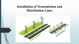
- 1. Installation of Transmission and Distribution Lines
- 2. Erection of steel structures The erection of steel structures in transmission and distribution lines involves the installation of towers, poles, and other supporting structures that carry electrical conductors and cables used to transmit and distribute electrical power over long distances. These structures are a crucial component of the power grid, enabling the safe and efficient transmission of electricity. Tower Pole
- 3. 1. Design and Engineering: Before any construction begins, detailed engineering and design work is carried out. This includes determining the types and heights of towers or poles needed, the spacing between them, and the conductor configuration. 2. Site Preparation: The construction site is prepared, which might involve clearing vegetation, excavating for foundations, and creating access roads for construction equipment. 3. Foundation Installation: In some cases, tower foundations might be required. These are typically concrete foundations that anchor the towers securely to the ground. The foundation design is critical to the structural stability of the tower. 4. Tower Erection: • Assembly: Tower components are typically prefabricated off-site. These components include tower legs, cross-arms, braces, and other structural elements. • Transportation: Towers are transported to the site, often in sections, and then assembled on- site. • Erection: Cranes and other specialized equipment are used to lift and position the tower components. Bolts or welding are used to connect the components securely.
- 4. 5. Conductor Installation: • Stringing: Conductors (wires or cables) are strung between the towers. Stringing involves using pulleys, tensioning equipment, and special tools to install the conductors along the designated path. • Clamping: The conductors are securely clamped to the insulators on the tower cross-arms. 6. Insulator Installation: Insulators are placed on the tower to prevent electrical current from flowing through the structure. These insulators are made of materials that are highly resistant to electricity. 7. Grounding and Bonding: Proper grounding and bonding are essential to ensure the safety of the transmission and distribution system. Grounding systems are installed to direct lightning and fault currents safely into the ground. 8. Testing and Commissioning: After the erection of the steel structures and installation of conductors, thorough testing is conducted to ensure that the system functions as intended. This includes checking for electrical continuity, insulation resistance, and other parameters. 9. Safety Measures: Safety measures are paramount throughout the construction process. Crews working on the transmission and distribution lines need to follow strict safety protocols to prevent accidents and injuries. 10. Environmental Considerations: Construction in environmentally sensitive areas might require additional measures to protect local ecosystems and wildlife. 11. Maintenance and Monitoring: Once the steel structures are erected and the transmission and distribution lines are operational, regular maintenance and monitoring are necessary to ensure the continued reliability of the system.
- 5. There are 4 main methods of the erection of steel transmission towers which are described below: 1. Build-up method or Piecemeal method- involves assembling the transmission tower piece by piece directly at the construction site. This method requires the tower components, such as steel sections and structural members, to be transported to the site and then assembled one by one. 2. Section method- The section method is similar to the build-up method, but instead of assembling each individual piece on-site, the tower sections are pre-assembled at a different location and then transported to the construction site as larger segments. 3. Ground assembly method- The ground assembly method involves constructing the transmission tower horizontally on the ground near the installation site. Once the tower is fully assembled in this horizontal position, it is then raised to its vertical position using specialized equipment such as cranes. 4. Helicopter method- This method is often employed in remote or difficult-to-access locations, such as mountainous regions or areas with limited road infrastructure. Helicopters can carry tower sections and components directly to the installation site, bypassing the need for ground-based transportation and assembly.
- 7. Main Towers Used in Transmission of Power Tangent towers- • They are most commonly found in areas where the transmission line follows a straight path. • Tangent towers are designed to carry the weight of the conductors and maintain proper tension in the lines. • About 85% of towers in transmission line are of this type. • The insulator used in these towers are provided vertically.
- 8. Angle tower Anchored towers- • These are used at the endpoints of a transmission line or at locations where the direction of the line changes significantly. • Play a crucial role in securely anchoring the transmission line and managing the tension at the ends of line. • Used to pass over highways, communication lines and small rivers. • It should be of robust and strong design with anchor and guy for additional strength. • Examples- Angle towers, Dead-end towers, transposition towers Dead end tower Transposition tower
- 9. Types of Poles Pole provide support to insulators, conductors of overhead (O.H) lines. Single pole and double pole The poles are of Reinforced Cement Concrete (RCC), Steel sections, or wood. Steel tubular sections are more costly as compared to wood and RCC poles.
- 10. Connecting jumpers “Jumper" generally refers to a short piece of conductor, often in the form of a wire or cable, used to establish a temporary or permanent connection between two points. Jumpers can serve various purposes, such as connecting two parts of a circuit, bypassing a component, or linking two conductors in a transmission line.
- 11. Jumpers can be used in transmission lines for a variety of reasons: 1. Fault Bypass: If a fault is detected in a section of a transmission line, a jumper can be used to bypass the faulty section temporarily while repairs are being made. This helps maintain the continuity of power transmission. 2. Isolation: Jumpers can be used to isolate a section of the transmission line for maintenance or repairs. By disconnecting a portion of the line with jumpers, the rest of the system can continue to operate. 3. Testing and Troubleshooting: Jumpers can be used to create specific test configurations for troubleshooting purposes. They can help engineers and technicians isolate parts of the system to identify the source of an issue. 4. Switching: In some cases, jumpers might be used to switch between different configurations or paths in a transmission system. This can help reroute power flow as needed. 5. Temporary Connections: Jumpers can also be used to establish temporary connections between transmission lines, equipment, or substations. This might be necessary during system upgrades or changes.
- 12. Tee-off points “Tee-off points" typically refer to specific locations or points along a power distribution or transmission line where additional connections are made to supply power to various loads or distribute electricity to different destinations. These connections are often made through branching lines that resemble the letter "T," hence the term "tee- off."
- 13. Here are a few key points about tee-off points: 1. Distribution Networks: Tee-off points are commonly found in distribution networks, where electrical power generated at a central source is distributed to various consumers or loads. 2. Substations: In larger electrical distribution systems, tee-off points might be associated with substations. Substations receive high-voltage power from transmission lines and then distribute it at lower voltages to local loads. The connections made at substations are often tee-off points. 3. Feeder Lines: A feeder line is a primary power line that carries electricity from a substation to a specific area. Tee-off points can be established along feeder lines to branch off power to different neighborhoods or industrial zones. 4. Load Management: Different branches can be controlled separately, enabling operators to manage power distribution based on demand fluctuations. 5. Reliability and Redundancy: If one section of the distribution network experiences an issue, power can be rerouted through alternate tee-off connections to maintain supply to critical loads. 6. Control and Automation: Modern distribution systems often use smart grid technologies. Tee- off points can be remotely controlled and monitored, allowing for more efficient management of the distribution network. 7. Safety and Isolation: Tee-off points can be designed to isolate certain sections of the distribution system for maintenance and repairs without affecting the entire network.
- 14. Conductor joints and dead ends Conductor joints refer to the points where two separate sections of a conductor are connected together. Conductor joints need to be properly made and maintained to ensure a continuous and low-resistance electrical path. Poorly made joints can result in increased resistance, leading to overheating and potentially causing fires or other electrical issues. Different methods are used to create conductor joints, including soldering, crimping, welding, and mechanical connectors. Conductor joints are essential for several reasons: 1. Long-Length Transmission Lines: Transmission lines can stretch over vast distances, and it's often impractical to manufacture a single continuous conductor of such lengths. Therefore, conductor joints are used to connect shorter sections of conductor together, allowing for efficient transportation and installation. 2. Maintenance and Repairs: Over time, power lines can experience wear and tear due to various factors such as weather conditions, vibrations, and thermal cycling. When damage occurs, conductor joints allow for the replacement of specific sections of the conductor without the need to replace the entire length. 3. Expansion and Upgrades: As power demand increases, new transmission lines may need to be added or existing ones upgraded. Conductor joints facilitate the extension of the existing network or the installation of higher-capacity conductors. 4. Flexibility: Conductor joints provide flexibility in designing and adapting transmission and distribution systems to different layouts and topographies.
- 15. A "dead end" refers to the point where a power line terminates or is anchored, at utility poles or transmission towers. The term can also refer to a section of power lines that isn't connected to any other lines. Dead ends are designed to secure the power lines and provide support against tension caused by the weight of the lines themselves and external forces like wind. Dead ends typically involve hardware components such as clamps, insulators, and tension devices. These components help distribute the mechanical load evenly and prevent the power lines from sagging excessively. Proper design and installation of dead ends are crucial to maintaining the stability and integrity of the power distribution network.
- 16. In high voltage O.H lines, different types of strain clamps are used for dead ending. 1. Single bolt strain clamp- Used for dead ending conductors medium or light duty transmission lines. 2. Two bolts strain clamp- Used for dead ending of conductor of main distribution lines and light distribution lines. The gripping power is more than single bolt strain clamps. 3. Multi bolt strain clamp- Used for dead ending heavy duty transmission and distribution lines. Provides sufficient gripping power to hold heavy duty line under tension. 4. Compression type dead end clamp- Used for dead ending ACSR conductor of transmission lines of voltages above 66 kV.
- 17. Planning the route of lines • Before deciding the line alignment, it is necessary to prepare a survey map of adjoining areas of proposed route. • It will help in assessing necessary details of construction with accuracy. Planning of a distribution system o Distribution system is required for the distribution of electrical energy. o Good planning is necessary for a development and long life of system and also to make maximum use of available resources. Load survey o Load survey of a particular area is carried out to find out present load requirements as well as expected load growth over a period of 5-7 years. o The following data should be collected: 1. Detailed map of area showing important feature. 2. The number of houses, population, and new constructions expected in area. 3. The number of shops, post office, rural health centres, panchayat offices. (present and expected) 4. 4. Details of hospitals, railway stations, public health sewerage system and water supply schemes.
- 18. 5. Cultivated area, number of wells, and available irrigation facilities. 6. Type and number of industries possible in area. 7. Development programme implemented and to be implemented. Load forecasting: For this purpose, the consumers may be classified as: Domestic consumers i.e. residential houses Commercial consumers i.e. shops, schools, hospitals, hotels. Industrial consumers: small industries (up to 20 kW), medium industries (up to 100 kW), Large industries (above 100 kW), municipal consumers, agricultural consumers.
- 19. Survey of Lines It is necessary to survey the area in order to determine the route along which a line is to be laid. The proposed route should be shortest practicable distance. o First step- Select the route and plot it on a map to a large scale. o Second step: Conduct a walk over survey to determine the topography of the area and any obstacles likely to come across. o Detailed survey to determine the quantity of material required for the line construction. o Route of line should be selected along an available road in the area as it will help in delivery of material as well as construction and maintenance. o While selecting route, following areas should be avoided: Wells Bridges Low lying areas Water logged areas Gardens Trees Building containing explosives Aerodromes Urban development areas
- 20. There are some special problems which must be considered when route of line crosses a river or railway line or national highway or telecommunication line or passes through a forest. • River crossing A data of high flood levels of at least 20 years should be obtained from revenue authorities and the structure are to be erected so that they remain approachable even under flooded conditions. For nan-navigable rivers, the transmission line structures should be designed in such a way so that the lowest conductor should be 3 m above the maximum flood level. This is necessary because flood waters may carry trees and their branches.
- 21. • Railway crossing- The regulations framed by railway authorities. o An O.H line should be at right angles to the tracks. But a deviation to the extent of 30 degrees may be permitted under unavoidable circumstances. o The distance between one of supporting structures and the nearest track should be equal to the height of structure above ground level plus 3 m. o All guards wire should be galvanised steel not less than 6 SWG for carrier wires and 10 SWG for cross-lacing. o Minimum permissible clearance between O.H line and railway track: Voltage Clearance between track and lowest conductor in ‘m’ Broad gauge Meter Gauge Inside station Outside station Inside station Outside station 1. Upto 650 V 7.2 7.2 6.1 6.1 2. 650 to 33 kV 10 7.6 8.6 6.4
- 22. • Crossing of roads o Guarding is done below line conductors when they cross roads. o It is crucial to ensure the safety of road users, pedestrians, and workers. o Two G.I. wires of size 3.15 mm are stretched under tension between the supports on either sides of roads and fixed to the cross arms. o The line should not cross the road at an angle less than 60 degree. Guarding S. No. Type of Road Width of Road Min. horizontal clearance between centre of road and line support 1 National highway 11.6 m 7.6 m 2 State highway 9.8 m 6.7 m 3 Major district roads 7.3 m 5.5 m
- 23. • Crossing of telecommunication lines o High voltage power lines sets up electric and magnetic field in its vicinity. The communication line under the influence of such field can experience electromagnetic or radio frequency interference, and induced voltages. o Power telecommunication co-ordination committee (PTCC) has set the code of practices: Telecommunication lines should be placed below the power lines because it requires constant attention for maintenance. The preferred angle of crossing between power and telecommunication line is 90 degree. But it should not be less than 60 degrees. The guard between both the lines may be fixed either to supports of power line or telecommunication line. • Forest area- While passing from forest area, permission should be obtained from forest authorities for carrying out the survey and for falling of trees so that minimum tree clearance is 1.8 m is obtained from conductor. Voltages Minimum clearance Above 33 kV and upto 66 kV 2.4 m Above 66 kV and upto 132 kV 2.7 m Above 132 kV and upto 220 kV 3 m
- 24. Earthing of O.H lines All metal supports of O.H line and metallic fittings should be permanently and efficiently earthed by: 1. Running continuous earth wire 2. Earthing each pole individually Ground wires or earth wires are bare conductors supported at the top of transmission towers. They serve to shield the line and intercept lightning stroke before it hits the current carrying conductors below. Ground wires normally do not carry current. Therefore, they are often made of steel. The ground wires are solidly connected to ground at each tower in transmission and distribution system. Method of earthing- A galvanized iron rod of 20 mm dia or a pipe of 40 mm dia is driven into ground, water is poured to keep the soil surrounding pipe or rod moisture. Earth wire is connected with the rod or pipe with help of a clamp. This type of earthing is provided on ordinary soils. Where the soil is hard, charcoal and salt layers are provided around pipe or rod in alternate layers to reduce earth resistance which should not be more than 10 ohms.
- 25. Guarding of O.H lines A guard wire is safety cage which runs along the distribution line. This wire is properly earthed. Guarding is provided to low, medium, and H.T overhead lines so that in the event of breakage of any phase conductor due to wind storm etc, it would first come in touch with cradle guard wires which are earthed, making the live conductor dead by tripping the circuit breakers. Guarding is necessary in O.H lines at following places: Types of Guarding- Cradle guarding, Cage guarding, Bird guarding Road crossing Railway crossing Rivers Canals Telephone lines
- 26. Cradle guarding- It is provided when the conductors are in horizontal formation. Cage guarding- It is provided when the conductors are in vertical formation. Bird guards- To overcome the fault conditions caused due to birds coming in contact with E.H.T lines bird guards are fixed over the suspension insulator strings in the saw tooth form.
- 27. Spacing of conductor The formula for conductor spacing is based on line voltage, span, weight of conductor, wind pressure on conductor and direction of swing. Generally, greater the span length, more should be the spacing distance between conductor for same working voltage to avoid touching between them in storms. For aluminium and its alloys, Spacing = √d + V/150 meters For other material, Spacing = 0.75 √d + V/150 meters d = sag in meters, V = Line voltage in kV
- 29. Type of Conductors In the early days conductor used on transmission lines were usually Copper, but Aluminium Conductors have Completely replaced Copper because of the much lower cost and lighter weight of Aluminium conductor. The symbols identifying different types of Aluminium conductors are as follows:- 1. AAC : All Aluminium conductors. 2. AAAC : All Aluminium Alloy conductors 3. ACSR : Aluminium conductors, Steel-Reinforced 4. ACAR : Aluminium conductor, Alloy-Reinforced AAAC have higher tensile strength than the conductor of AAC, ACSR consists of a central core of steel strands surrounded by layers of Aluminium strands. ACAR has a central core of higher strength Aluminium Alloy surrounded by layer of Electrical-Conductor-Grade Aluminium. Very recently, a new type of composite using ceramic fibers in a matrix of aluminum has been introduced that has lighter weight and higher strength. These are ACCR cables (aluminum conductor composite reinforced). This new conductor has the advantage of high strength even at elevated temperatures, and the addition of zirconium to the aluminum alloy makes it more resistant to degradation at high temperatures.
- 30. Standard Sizes of Conductor for Lines of Various Voltages
- 31. Configurations of conductor 1. Single-Circuit Configuration: In this configuration, each tower or pole carries a single set of conductors for a single phase. Single-circuit lines are suitable for lower voltage levels and simpler installations. 2. Double-Circuit Configuration: In a double-circuit arrangement, two sets of conductors for different phases are strung on the same set of towers or poles. This configuration is commonly used to increase the capacity of transmission lines while minimizing the number of structures. 3. Bundle Conductors: Bundle conductors involve grouping two or more individual conductors together in a single phase. Bundling reduces the overall inductance, improves current-carrying capacity, and mitigates the effects of corona discharge. 4. Quad-Bundle Configuration: This is an extension of the bundle conductor concept, where four conductors are grouped together. Quad-bundle configurations are often used for extra-high voltage transmission lines.
- 32. Insulators Provide electrical insulation and mechanical support. They prevent electric current from flowing between the conductive wires and the supporting structures. These are meant for supporting O.H conductors and are fixed on cross arms. Various types are: 1. Pin Insulator- Used in power networks up to 33 kV system. Support conductors in intermediate poles but do not take any tension. 2. Suspension Insulator- The numbers of insulators are connected in series to form a string and the line conductor is carried by the bottom most insulator. Each insulator of a suspension string is called disc insulator because of their disc like shape. Each suspension disc is designed for normal voltage rating 11KV, so by using different numbers of discs, a suspension string can be made suitable for any voltage level. 3. Strain Insulator- When suspension string is used to sustain extraordinary tensile load of conductor it is referred as strain insulator. When there is a dead end or there is a sharp corner in transmission line, the line has to sustain a great tensile load of conductor or strain. Pin
- 33. 4. Post Insulators: Post insulators are used to support busbars and other equipment in substations. They are mounted vertically and are designed to withstand both electrical and mechanical stresses in a substation environment. 5. Glass insulator- These insulators were prevalent during the earlier days of electrical distribution and transmission systems. However, due to advancements in materials and technology, other types of insulators, such as porcelain and composite insulators, have largely replaced glass insulators in modern power systems. 6. Stay Insulator- Used in low voltage lines to provide electrical insulation and mechanical support to stay wires in power distribution and transmission systems. Stay wires are used to provide additional support to utility poles or structures, preventing them from leaning or falling due to the tension forces applied by the overhead conductors. 7. Shackle Insulator- Used in distribution networks that works with low voltage is known as a shackle insulator. At present, the usage of this insulator has decreased because of the underground cable used in distribution purposes.
- 35. Anti climbing devices and danger plates Anti-Climbing Devices: • Anti-climbing devices are installed on utility poles, transmission towers, and other structures to discourage individuals from attempting to climb or access the equipment. • Climbing on power structures poses serious risks, including the potential for electric shock and accidents that can lead to injury or death. • Anti-climbing devices are designed to create physical barriers that make it difficult or nearly impossible for unauthorized personnel to climb the structure. • Common types of anti-climbing devices include: 1. Barriers and Guards: These are typically metal or plastic structures that cover the lower portions of poles or towers, making it difficult for people to grip or scale the structure. 2. Razor Wire : These types of barbed wire are used as a deterrent on the perimeter of power structures, making climbing extremely challenging and dangerous.
- 36. Danger plates, also known as warning signs or caution signs, are prominently displayed near high- voltage equipment and overhead lines to alert people to the potential hazards. These plates provide clear information about the presence of dangerous electrical equipment and the risks associated with proximity or contact. Danger plates typically include text, symbols, or pictograms that convey the message of danger. Some common information found on danger plates may include: 1. High Voltage Warning: The plate may include text or symbols indicating the presence of high-voltage equipment or overhead lines. 2. Electrical Hazard: Warnings about the risk of electric shock or electrocution. 3. No Trespassing: Indicating that unauthorized access is prohibited. 4. Safety Instructions: Guidelines on safe behavior around the equipment, such as maintaining a safe distance. 5. Emergency Contact Information: Contact details for reporting emergencies or unsafe conditions.
- 37. Size of conductor Factors which decides the size of the conductors designed for distribution system are given below: • Current carrying capacity of the conductor • Tensile strength of the conductor • While considering current carrying capacity of the conductor the maximum temperature which it can withstand easily has to be taken into consideration. • For aluminum cored conductors this temperature is 75 degrees. If temperature increases beyond this limit the conductor starts annealing and its tensile strength is reduced. After sometime, the conductor will melt and will be broken. • The tensile strength of conductor is sufficient to withstand the mechanical forces acting on it due to length of span, wind and other atmospheric conditions. • If it is not found suitable to withstand such pressures then a higher conductor size should be taken.
- 38. Guys A galvanized steel wire either single or stranded, one end of which is attached to a structure (pole) and other end is attached to anchor. Guys is used in case of all angle and tension supports such as wood poles, RCC poles, etc. Overhead lines poles at terminals angles and tee offs have a tendency to be pulled away from the true vertical position. Therefore to overcome this, guys are used. Digging of Guy Pit- The guy rod is held by the guy plate inside the ground. The guy pit must be dug carefully. The angle of guy must be between 30°- 45 °.
- 39. Testing and Commissioning of O.H Distribution Lines General Inspections- Before the line is energised, visual inspection of the line should be carried out to check that all nuts and bolts are tight and the insulators are in position at each support. The earth connections should also be checked properly. Testing- After the erection of 11 kV at L.T. lines the following tests should be conducted before commissioning of lines: a) Conductor Continuity Test- To verify that each conductor of O.H line is electrically properly connected. Electrical continuity of line is checked with the help of a continuity tester and or a multimeter set to continuity mode. b) Insulation Resistance Test- i) For L.T line of 115V/240 V: Each phase and neutral of line should be tested for leakage with a 500 V Megger. Insulation of each conductor should not be less than 2 MΩ. ii) For 11 kV line: Each phase of line should be tested for leakage with a 1000 V megger. Insulation resistance of each conductor should not be less than 50 MΩ. c) Earth Resistance Test- It should be carried out with an earth resistance tester on the earth wire on 3-poles per km of the line on metallic fittings. If the resistance is higher than 10Ω, the earthing arrangement should be improved to bring down the earth resistance to 10Ω.
- 40. Commissioning of the Lines- After checking the line and checking its actual conditions the chief electrical inspector of state is informed that line is ready for his inspection. The 11 kV lines should first be energised at L.T voltage and after a few hours of satisfactory operation, the line may be commissioned at rated voltage. Routine Inspection of O.H lines- All O.H lines should be patrolled regularly each month by inspector at ground level when the line is live. The important parts to be checked: 1. Supports- Check metal supports, wooden poles, PCC and RCC poles. Check concrete foundation, soil erosion, pole alignment, any leakage, cracks. 2. Cross arms- These may get rusted or tilted (metallic crossarm) or decaying due to rot (wooden crossarm). 3. Insulators and fittings- Check for any defects-broken, tilted insulators, accumulation of dust, rusting of fittings, burnt spots on glaze of insulator. Damaged insulator should be replaced and dirty ones should be cleaned after disconnecting lien from supply. 4. Conductors and earth wires- Clearance between phase wires and clearance with ground should be checked. In case of sag it should be corrected after disconnecting the line from supply. 5. Conductor fittings and joints- Looseness of binding on insulators and at joints, slip of conductor from insulator sheet, broken strands, burnt jumpers and loose fittings on clamp.
- 41. 6. Guys and their accessories- Loose guys, broken chipped of guys insulators, earthing arrangement of guys broken and missing, corrosion of guy rods, condition of guy anchoring. 7. Gang operated switch or fuse unit on 11 kV line- Defective switch, missing or broken earth wire, cracked or chipped insulator, burning or overheating of contacts, damaged arcing contacts. 8. Lightning arresters- The lines lead of lightning arrestor should be firmly connected with the phase wire. Earth connection should be tight and earth resistance should be less than 10 ohms. 9. Tree clearance- Trees or branches coming close to lines should be trimmed. A minimum clearance of 1.8 m should be maintained. Also remove grass from neighbourhood of line during inspection. 10. Bird Nests- These should be removed from O.H lines, crossarms and change damaged insulators. 11. When soil is very loose. Clamps should be used around the pole beneath the ground. 12. Vertical alignment of pole should be checked. 13. Earth electrodes should be watered from time to time. 14. Earth resistance should be checked from time to time. 15. Sag should be checked for permissible units. 16. Stay assembly should be checked for proper tension. 17. Annual check- Inspect individual tower. Inspect O.H electrical fittings including insulators and mechanical connectors. Wash insulator with water. Replace cracked insulators.
- 42. Service connection The cable (overhead or underground) which supplies electric power from the supply pole to consumer’s terminals is called service mains or service line. In single phase supply (domestic loads), the service main has three wires, namely phase wire, neutral wire, and earth wire, running from supply at pole to consumer’s premises upto energy meter installed. In three phase supply (industrial loads), five wires run from service pole to consumer terminals. Three wires are for three phases, fourth wire is neutral and fifth wire is earth wire. 1. Low voltage supply at 230 V AC for demand of power not exceeding 4 kW. (houses and shops) 2. Medium voltage supply at 400 V AC for demand of power not exceeding 50 kW. (Residential building and small factory) 3. High voltage supply at 3.3 kV, 6 kV, 11 kV and 33 kV AC for demand of power above 50 kW. (multi storey building in big industry)
- 43. In construction of O.H service line, the following points should be kept in mind: 1. The service span should be limited to 35 m. 2. The service line should be fed of only from the pole and not from mid span. 3. The pole selected for teeing off should be straight properly. Service line- A line connecting the consumer installation to a distributor. It is the last line of the network transmitting power from the power station to consumer. There are two types of L.T service lines. i. Bare wire service line- AAC is used for phase and neutral and most used earth conductor is number 8 SWG G.I wire. ii. Catenary wire and insulated cable line- Weather proof cable should be used for aerial cable. Aerial cable should not have any joints. Only G.I wire of hard drawn quality of number 8 SWG should be used for earth wire. The aerial cable should be treated through reel insulator. There are two types of service connections. i. Overhead service connections ii. Underground service connections
- 44. i. Overhead service connections- • If consumer premises is more than 45 m away from nearest distribution line support then service connection will be by O.H bare conductors. If the consumer premises is less than 45 m away then service connection is by means of weather proof or PVC cables. • In double storey building, if service connection is by bare conductor, then service bracket is placed into wall. Wires are taken from service pole to shackle insulators and fixed to bracket connections and then taken to energy meter by weather proof or PVC cables. ii. Underground service connections- • This is used where heavy loads above 25 kW are to be applied. • Paper insulated cable terminates at each end into a cable box. • To protect cable from any mechanical damage it is run through G.I pipe of 2 m length, where it rises at pole and at service board. • Cable is held to pole by means of pole clamp.
- 45. Service fuses Pole fuse- An aerial fuse provided on pole to protect the distribution system and the connected equipment from overcurrent and short circuit. Supplier’s fuse- The aerial fuse protects only service cable and not energy meter. To protect the energy meter, supplier fuse is used. Each consumer have independent supplier fuse. Switch fuse- For controlling the supply to the consumer, double pole linked switches are used to protect wiring between main switch and distribution board. Kit-kat fuse- These are inserted in distribution board. The size of kit kat fuse wire depends upon maximum current of circuit. In short circuit or heavy load, it protects cables from being damaged.
- 46. Installation of energy meters The number of meters required for any particular installation will depend mainly upon tariffs and methods of payment offered by supply authority, and chosen by consumer. At present a number of different types of tariffs is offered by supply authority in various parts of country and involves various methods of metering. The size of energy meter chosen for any particular premises must be large enough to deal adequately with the load to be registered, but not large as to be uneconomic at light loads.
- 47. Installation of energy meter- • For most installations, energy meter are fixed to wooden boards and care should be taken that these boards are mounted on a rigid structure like a wall. • Situations where meters might receive shock transmitted from slamming a doors etc. might be avoided. • The energy meter should be installed in consumer’s premises and near to the cut out as possible. • They should be easily accessible in order to provide consumer with minimum amount of trouble in operating the meters.
- 48. Special metering arrangement- In factories and other large industrial or commercial premises the particular tariffs in operation frequently requires special metering arrangements like- Maximum demand metering- For many commercial and industrial customers, electricity bills are calculated not only based on total energy consumed (measured in kWh) but also on the highest level of power demand. MD metering uses a predefined demand interval, usually 15, 30, or 60 minutes. During this interval, the meter records the highest demand observed. Kilo-volt ampere hour metering- This is often used by utility companies and large consumers of electrical energy for billing purposes. It can also provide load profiling information, helping users understand their power consumption patterns. A low power factor indicates inefficient use of electrical energy due to reactive power consumption. kVAh meters help identify and monitor power factor issues.