
Recommended
More Related Content
Viewers also liked
Viewers also liked (10)
Similar to NRCan_Wireless_Power_Test_Procedure_Investigation_Final
Similar to NRCan_Wireless_Power_Test_Procedure_Investigation_Final (20)
NRCan_Wireless_Power_Test_Procedure_Investigation_Final
- 1. PAGE 1 | Wireless BCs Test Procedure Recommendations MEMORANDUM To: Augustine Orumwense and Marc Ostrowski, Natural Resources Canada From: Suzanne Foster Porter, Dave Denkenberger, PhD, David Thomsen, Brian Spak, Ecova Date: March 28, 2014 Subject: Wireless Battery Charger Test Procedure Investigation and Recommendations ___________________________________________________________________ SUMMARY Our review of the U.S. Department of Energy’s battery charger test procedure concluded that the test procedure accommodates wireless battery chargers currently available in Canada. Our market research revealed that only near-field wireless battery chargers (i.e. products in which the charger and the battery are in physical contact) are available in Canadian retail outlets. We recommend a few clarifications to the test procedure to improve clarity and ensure repeatability. In no way do these changes affect the overall test procedure approach or framework, timing, equipment required or other technical elements of the test procedure. Recommended clarifications include: specifying language regarding rest of wirelessly charged batteries broadening the definition of cradle to explicitly include wireless battery chargers ensuring testing on an electrically nonconductive surface guiding language for the placement of the wireless battery on the charger In addition to the clarifications that we recommend that NRCan pursue, this memo discusses some additional issues related to the test procedure and its applicability to wireless battery chargers not currently on the market. While NRCan could amend the test procedure to resolve these issues, we do not recommend doing so at this time, because the changes are non-substantive or we lack data to support the change. These include testing the battery at the edge of the physical charging range and including a radiofrequency shielded box. Additionally, in the appendix, we list further opportunities to improve clarity of the the test procedure for all battery chargers, wireless and wired, that we uncovered while conducting our investigation. INTRODUCTION AND OBJECTIVES “Wireless power products,” which provide power to a product without a wired connection, have recently entered the market. The enabling technology differs depending on the device, but depends on
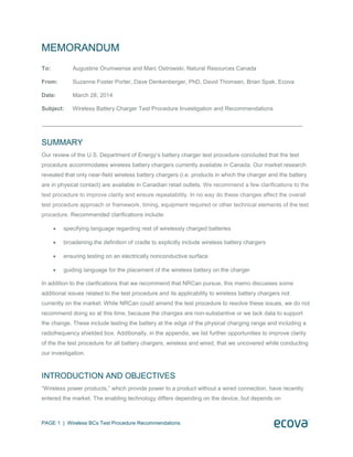
- 2. PAGE 2 | Wireless BCs Test Procedure Recommendations electrodynamics, electrostatics, microwaves or lasers. Three broad categories of wireless power technology exist: i) far field or radio frequency (i.e. the charger and the battery are a few meters apart); ii) mid-range or far edge inductive coupling (i.e. the charger and the battery are a few centimeters apart); and iii) near field (i.e. the charger and the battery are in physical contact). The scope of this project was limited to near-field inductive devices, the only wireless power products commercially available in Canada in late 2013. This project had two objectives: to survey wireless power products in the Canadian market and to determine the applicability of the United States Department of Energy’s (DOE) external power supplies and battery charger test procedure for measuring the energy performance of wireless power devices. This memo aims to support NRCan’s participation in the Canadian Standard Association’s efforts related to the development of external power supplies and battery chargers test procedures. MARKET SURVEY, PRODUCT SELECTION, AND METHODOLOGY To understand the market of near-field inductive devices, we researched available products through identification of the common products available in online Canadian store catalogs and telephone conversations with in-store employees to determine the stock at several major retailers in the Ottawa region. The survey uncovered two trends: First, near field inductive charging devices available in Canada largely cater to smart phones and game console controller devices. Secondly, these chargers are primarily offered online (store representatives recommended buying wireless chargers online). The two devices we chose to purchase represent the range of products in the market, ensuring that our evaluation of the applicability of the DOE test procedure represented current products. Of the available devices, we chose the Duracell Powermat pad compatible with mobile devices and inductive batteries from Amazon.CA1 and the dreamGear DGWII-3116 Wii remote charger, capable of charging four remote game controllers for the Nintendo game console, Wii. The dreamGear device was available from FutureShop.com, BestBuy.CA and Amazon.CA. Figure 1 shows the two chargers. Additional batteries, a cell phone for the Powermat and Wii controllers for the dreamGear were required to test the products according to the DOE test procedure. Table 1 lists all items purchased. 1 This Powermat is capable of charging two batteries at once.
- 3. PAGE 3 | Wireless BCs Test Procedure Recommendations Figure 1: Duracell Powermat (left) and dreamGear Wii Remote Charger (right) The Duracell Powermat is compatible with smart phones with wireless charging cases and specially designed inductive batteries. As a multi-capacity, multi-voltage, and multi-port battery charger, the Powermat requires three tests: lowest voltage (lowest charge capacity, one port), highest voltage (highest charge capacity, one port), and highest energy capacity (all ports). Table 1 Item Description Category dreamGear Wii remote charger for 4 remotes (DGWII-3116), four NiMH rechargeable battery packs Inductive Charging Mat, Batteries Rock Candy Nintendo Wii Remote Controller ( Model # PL8560GR) Wii Remote Nintendo Wii U Remote Plus (WebID # 10227199) Wii Remote Wii Remote Plus Controller (Model # RVLAWRPA) Wii Remote Collective Minds Nintendo Wii U Motion Plus Deluxe Kit (Model # CM00059) Wii Remote Duracell Powermat for two devices kit (Model # CSA4B1), iPhone 4 wireless charging case and Duracell GoPower Day Trip Battery (5V, 1850 mAh) Inductive Charging Mat, Battery, Phone Charging Case Duracell GoPower Long Haul Battery (5V, 8800 mAh) x3 Battery (x3) Apple iPhone 4 (A1349)- integrated phone battery (3.7V, 1420 mAh) Smart Phone * An additional Duracell Powermat for 3 devices was purchased for comparison ENGINEERING INVESTIGATION I.Methodology for investigation Based on the understanding of the battery charger test procedure and the fundamental science behind wireless battery chargers, we looked in particular at two potential issues that could affect the applicability of the test procedure to these wireless charger systems: battery selection and displacement. We also conducted a thorough review of the entire test procedure language with the physical products in hand to understand any other possible issues not in our original hypothesis. To determine the suitability of the
- 4. PAGE 4 | Wireless BCs Test Procedure Recommendations DOE battery charger test procedure, we conducted a physical inspection of the selected products and investigated the performance of one of the products. II.Battery Selection After we determined the chargers to purchase, we used the DOE test procedure to select the batteries. We first determined the range of possible batteries in order to understand the number of tests required. Then, these individual tests dictated which batteries to purchase. This process is identical for other chargers sold without their batteries (car battery chargers, power tool chargers, some chargers capable of charging many standard types of rechargeable batteries that replace primary batteries (AA, AAA, C and D). Wireless products have battery selection requirements similar to many wired battery charger products already covered by the test procedure. The test procedure’s existing requirements for battery selection apply to wireless battery chargers just as they do for wired chargers. III.Displacement We chose the Duracell Powermat for further engineering investigation because it allowed greater freedom of movement of the products being charged than the dreamGear2 remote charger; we hypothesized that this freedom of movement would impact the efficiency of the product. We conducted a performance evaluation with the largest battery to provide the greatest resolution of the potential for differing efficiency based on the placement of the battery on the charger. The battery was charged and discharged both with the magnets and coils aligned (on center) and offset at 3 mm from center. Table 2 shows that the 24-hour charger efficiency falls by about five percent when the charger is on the edge of the viable charging range (3 mm offset from center). We found that the results were repeatable to within one percent. Table 2 Location Energy (Whrs) Charging Energy (Whrs) Discharging 24 hour efficiency 2 The dreamGear Wii charger, able to charge up to four Wii remote devices, had designated grooves on the surface that limited orientation of the battery when charging, significantly limiting the different battery layout options and effectively preventing battery displacement (see Figure 1).
- 5. PAGE 5 | Wireless BCs Test Procedure Recommendations On center 69 34 49% Offset 3 mm 73 34 46% From this investigation, we recommend that the test procedure include clarification language that states the battery shall be placed in the specified location, or barring that, placed according to the manufacturer’s instructions (see Table 3). As products evolve and new products are introduced, it is possible that an additional test to understand the specific efficiency impact of placing the battery in different locations on the charger could be appropriate (see Table 4). While this additional test would provide more data, it would also increase the testing burden. In addition, it is unclear to what degree, if any, the difference observed in the lab would manifest itself in the field because strong magnets present in some current products may automatically align the coils. Indeed, the design of the Duracell Powermat did not allow displacement of the battery to be offset greater than three mm. IV.General investigation We concluded in our assessment of Canadian wireless products that the market and technology of wireless battery chargers are very similar to wired chargers. The wireless products are targeted for consumer use; they are set up and operate similarly to other consumer battery chargers. The main difference is that they have a receiver and a transmitter instead of a direct electrical connection to transmit power from the charger to the battery. This affects efficiency and functionality, but it does not substantially change the way they need to be tested. As a result, the general approach, the timing, the instrumentation, etc. in the test procedure were all found to be appropriate. We found a few additional opportunities for clarification to help ensure repeatability of the test approach to these chargers (see Table 3): 1. adding a definition of wireless battery chargers, 2. adding language regarding rest of wirelessly charged batteries, 3. broadening the definition of cradle to explicitly include wireless battery chargers, and 4. ensuring testing on an electrically nonconductive surface. Table 3 DOE Test Procedure section Problem/issue Possible solution/resolution 2.8; 2.9 No definition of wireless battery charger A wireless battery charger is a battery
- 6. PAGE 6 | Wireless BCs Test Procedure Recommendations charger that transfers charging energy via a non-conductive route. 2.9 This section says “Battery rest period is a period of time between discharge and charge or between charge and discharge, during which the battery is resting in an open-circuit state in ambient air.” The term open circuit does not apply for wireless chargers considered in this study. Change to “Battery rest period is a period of time between discharge and charge or between charge and discharge, during which the battery is resting in ambient air in an open-circuit state for conductive chargers and outside the viable charging range for wireless chargers.” 2.11 Definition is not clear whether an inductive pad is considered a cradle. Change “electrical interface” to “conductive or inductive interface” to clarify that an inductive pad could be considered a cradle. 3.3 “The UUT shall be conditioned, rested, and tested on a thermally non-conductive surface.” Electrical conductivity of the surface could affect a wireless charger. Replace with “The UUT shall be conditioned, rested, and tested on a thermally and electrically non-conductive surface.” 5.6 c. (5) refers to placing in cradle “If the charger does not have a specific physical location required for the battery on the charger, place battery according to manufacturer’s instructions.” Lastly, our research identified an additional, potential issue with the test procedure. While we do not recommend changes to the test procedure to address this issue at this time, it is worth monitoring going forward. The test procedure could require the use of a radiofrequency (RF) shield box to prevent stray RF signals from affecting wireless charger operation. For wireless small network equipment, the ENERGY STAR test procedure specifies the use of an RF shielded box. While the science suggests that the use of such a shield may be justified for wireless battery chargers, it would increase the testing burden and we have not measured the impact of stray RF signals on product performance during the test procedure. Table 4 DOE Test Procedure section Problem/issue Possible solution/resolution 5.6 c. (5) refers to placing in cradle “If the charger is wireless, place battery according to manufacturer’s instructions for the required tests. In addition, if the charger is wireless, do one additional test which is a repeat of the required test with the greatest energy capacity with the battery on the edge of the viable charging range.” 5.6 Stray RF signals could affect wireless charger operation. “If the battery charger is wireless, place the UUT inside a shielded enclosure large enough to fit the UUT without contact with enclosure walls (or floor – elevate UUT with a thermally and electrically non-conductive slab). The enclosure must have sufficient RF absorbing material lining all inside surfaces and also have sufficient feed-throughs to service the UUT.”
- 7. PAGE 7 | Wireless BCs Test Procedure Recommendations V.Conclusion Our investigation of the US DOE test procedure determined that the test procedure as currently written applies to wireless power products. A reasonable reading of the test procedure and a good faith approach by a laboratory certified to test battery chargers should produce a fair and accurate rating of the energy consumption of a given wireless battery charger. We recommend amending the test procedure in a few instances to improve clarity and ensure repeatability, but even absent these changes, the test procedure currently applies to wireless products available for retail purchase in Canada. APPENDIX Through our investigation, we discovered that the test procedure could be amended to improve overall clarity for the testing of all battery chargers, both conventional and wireless. Table 5 summarizes these recommendations. Table 5 DOE Test Procedure section Problem/issue Possible solution/resolution 4.5, 5.3, Table 5.2 “C” is ambiguous Replace “C” with “C-rate” 5.2 This section talks about indicators located in the battery charger that show if the battery is fully charged. What if the indicators are located in the specific battery used by the charger? Replace “If the battery charger has an indicator to show that the battery is fully charged” with “If the UUT, battery charger, or battery has an indicator to show that the battery is fully charged” 5.8 In part C.2 of this section it reads “Set the battery analyzer for a constant discharger current of 0.2 ˚C” Replace “0.2˚C” with “0.2 C-rate based on labeled capacity (or experimentally determined capacity if there is no capacity label)”