SlideShare a Scribd company logo
1 of 18
62462 Project 3 in Circuit theory and Analog
Group 4
Metal
Detector
28. maj
2014
Abstract
This report is documented for Metal Detector System. The
goal is to analyze, design, model, simulate and construct
the Metal Detector System. A very simple Design Pattern
was used to modulate the system with the use of less
number of components. Coils were designed in
consideration to the principles of induction for the Metal
Detector System. Standard components were used to
construct the Signal Processing Unit (ASPU). The design
for the ASPU was simulated and tested using advanced
simulation software called Pspice. The final Product
fulfills the requirements as expected.
Supervisor
Abdallah Ahmad Ibrahim Al-Mass
Assistant Lecturer
DTU Ballerup Campus
aalm@dtu.dk
Lars Maack
Head of studies,
Associate professor
lmaa@dtu.dk
Students:
Danish Mohammed Ali Bangash - s104712
Arier Azad Jaff - s121635
Nobert Nikolas Kruz - s127648
62462 Project 3 in Circuit theory and Analog
Group 4
Note: For Schematics, Test Results and Block Diagram Of the system please refer to the appendices at the last part of the report
1
Table of Contents
1 Introduction ............................................................................................................................................... 2
1.1 Project start........................................................................................................................................ 2
1.2 Problem Formulation......................................................................................................................... 2
1.3 Milestone Plan................................................................................................................................... 3
2 Problem Analysis....................................................................................................................................... 3
3 Project Delimitation and Methods............................................................................................................. 4
3.1 Solution Strategy ............................................................................................................................... 4
3.2 Requirements..................................................................................................................................... 4
3.3 Problem Solution............................................................................................................................... 5
3.3.1 Block Diagram Representation of the System........................................................................... 5
3.3.2 Metal Object .............................................................................................................................. 5
3.3.3 AC Signal .................................................................................................................................. 5
3.3.4 Transducer Part.......................................................................................................................... 5
3.3.5 ASPU Part ................................................................................................................................. 5
3.3.6 Transducer ................................................................................................................................. 6
3.3.7 Analog Signal Processing Unit (ASPU).................................................................................... 6
3.4 Resources (Hardware / Software)...................................................................................................... 9
4 Conclusion............................................................................................................................................... 10
4.1 Product Assessment......................................................................................................................... 10
4.2 Process Assessment......................................................................................................................... 10
5 Appendixes.............................................................................................................................................. 11
5.1 Appendix 1. (Schematics)................................................................................................................ 11
5.1.1 Amplifier ................................................................................................................................. 11
5.1.2 Active Full Wave Precision Rectifier...................................................................................... 11
5.1.3 Active Low Pass Filters In Cascade ........................................................................................ 12
5.1.4 Full System Schematic ............................................................................................................ 12
5.2 Appendix 2. (Transducer Test)........................................................................................................ 13
5.3 Appendix 3. (ASPU Tests).............................................................................................................. 14
5.4 Metal Detector Test ......................................................................................................................... 15
5.5 Appendix 4. (Calculations).............................................................................................................. 16
5.5.1 Coil related calculations: ......................................................................................................... 16
62462 Project 3 in Circuit theory and Analog
Group 4
Note: For Schematics, Test Results and Block Diagram Of the system please refer to the appendices at the last part of the report
2
Preface
This report is fully packed with documentation of the metal detector system. It covers the important aspects
of the product and the process of developing the System.
The problem formulated is the combination of electro physics and circuit theory to implement the system
that can be used in real life as well.
The reader of the report should have the basic knowledge and understanding of the system or any related
theory.
1 Introduction
1.1 Project start
The goals for the project is to analyze design, construct, test and simulate a metal detector system. The
System should have to be able to detect any metal object under it but only metal.
It can be used for any security purposes at the airport or any metal restricted areas, many companies
require this product too for organic processes to evaluate the metal objects contained in any organic
processes like recycling and checking for metals.
1.2 Problem Formulation
For the metal detector there will be the need of a transducer, which operates with the input which is the coin
or metal object, the transducer is powered by the function generator, transducer consist of 3 coils, which
convey one energy domain to another energy domain. Transducer operates with the frequency of 10 kHz.
Copper wire is used for the construction of the coils.
An active precision rectifier has to be used to change the AC signal to a DC signal. The reason why the
rectifier should be active is that we amplify the signal; non-active rectifier has a voltage drop over the diodes.
An active low pass filter is used which are constructed using the OP-Amps with a reason to amplify the
signal as like the rectifier. However we are using two active low pass filters on of them makes the signal
smooth but reverse and the other does the same and have a high gain before the output.
And then the signal will be reversed by each other and generate an output of 5V DC with reduced noise and
smoothens the signal.
All the modules combined together will be the metal detector system.
62462 Project 3 in Circuit theory and Analog
Group 4
Note: For Schematics, Test Results and Block Diagram Of the system please refer to the appendices at the last part of the report
3
1.3 Milestone Plan
Week Number
Task 12 13 14 15 16 17 18 19 20 21 22
Project Start x
Problem Formulation x
Block diagram x
Milestone Plan x
Create Transducer x
Testing Transducer x
Create ASPU x Holidays x
Testing ASPU holidays x
Simulations x
Adjustments x x
Error Correcting x x
Finish report x x
2 Problem Analysis
For the metal detector we will need a coil for detecting the metal part. Transducer consists of one transmitter
coil and two receiving. The transmitter coil is connected to a function generator. The receiving coils are
placed inside the transmitter coil, with each in the opposite direction of each other.
By placing the receiving coils in opposite directions of each other the B-field will be nullified by each other.
The small coil is connected to the ASPU, which gives the required output. Inside ASPU the AC signal gets
amplified, by the amplifier then the output is passed on to the rectification. A low pass filter is introduced in
order to ensure the output ripple is within the requirements.
62462 Project 3 in Circuit theory and Analog
Group 4
Note: For Schematics, Test Results and Block Diagram Of the system please refer to the appendices at the last part of the report
4
3 Project Delimitation and Methods
3.1 Solution Strategy
A Precision Rectifier is used, also known as the Full Wave Precision Rectifier the topology used is based on
two stages, HWR and a summing stage. Two Low Pass Filters are constructed in cascade to filter the
rectified signal the designed is properly calculated and simulated with respect to the preset requirements.
For the purpose of the induction, outer coil called the transmitter coils was mounted on the top of the plastic
plate and the inner coils called the receiver coils are placed precisely measured as fitted inside the transmitter
coils.
3.2 Requirements
Here we have specified the requirements for the metal detector.
System requirements:
 Reference Test Object: A Danish “5 KRONER” coin
 Reference Position: Test Object is 1 cm from the transducer at the place, and an orientation, where
the sensitivity is best.
 Output DC voltage when the Reference Test Object is at its reference position: VOUT = 5 V ± 0.5 V
 Output DC voltage with no metal object: VOUT = 0 V ± 0.5 V
 Output peak to peak ripple voltage: Vout peak-to-peak ≤ 20 mV
Transducer requirements:
 The transducer must be of type “Continuous Wave - Differential coil” operating at 10 kHz
 The transducer output voltage must be zero initially and as big as possible when metal is nearby.
 The transducer must be driven from a standard lab function generator with 50 ohm output resistance.
 The transducer must have a flat physical design and be homemade. You must decide the number of
turns, size and geometries.
 The design should be explained from electro physics formulas and sketches or simulations of the
magnetic fields
Analog Signal Processing Unit (ASPU) requirements:
 The ASPU must convert the transducer output signal into a system output voltage as specified under
“System Requirements”
 The transducer may pick up unwanted external noise in a broad frequency range. To reduce this
noise, the transducer + ASPU input stages, must have a 3-dB bandwidth of maximum 4 kHz
Additional requirements:
 Potentiometers or variable resistors are in general unwanted, but if needed it can be accepted for fine
tuning the output voltage e.g. for sensitivity adjustment
62462 Project 3 in Circuit theory and Analog
Group 4
Note: For Schematics, Test Results and Block Diagram Of the system please refer to the appendices at the last part of the report
5
3.3 Problem Solution
3.3.1 Block Diagram Representation of the System
Figure 5: Block Diagram of the System
3.3.2 Metal Object
The metal object is to be scanned on the transducer part for the purpose of metal detection.
3.3.3 AC Signal
Transducer takes Ac input from the function generator at the frequency of 10 kHz.
3.3.4 Transducer Part
Transducers were constructed by hand, transducer consist of an outer coil called the transmitter coil
and the two inner coils called the receiver coils. The coils were tested to measure the output generated
from the coil.
3.3.5 ASPU Part
The ASPU was started by designing the circuit and analyzed using simulation process, Orcad Pspice
was used for this purpose; the output of the system was verified by the simulation process.
Furthermore after the simulation process the design was implemented on a Printed Circuit Board, in
short “PCB “. The PCB was constructed twice first time it emerged with the some minor issues like
miss connections and wrong placements of the components. Second time the board was tested and
worked as expected.
62462 Project 3 in Circuit theory and Analog
Group 4
Note: For Schematics, Test Results and Block Diagram Of the system please refer to the appendices at the last part of the report
6
3.3.6 Transducer
The transceiver coil generates a B-field by the 10 kHz alternating current signal form the function generator.
The two inner coils in the system are a transmitter coil and receiver coil. The inner coils will counter the B -
field with a B - field from the induced current.
This will lead to an induced current and voltage:
( )
( )
These formulas are defined by Faraday's law of electromagnetic induction.
Both inner coils will create a B - field. The B - field of the receiving coil will be opposing the B - field of the
transmitter coil due to their turning in opposite directions. It is important to design these two receiver coils of
same size and turns so that they nullify each other when there is no coin.
By holding a coin over the receiving coil a drop in voltage happens, since adding an extra B - field will
reduce the voltage.
This will lead to detection of the coin.
3.3.7 Analog Signal Processing Unit (ASPU)
3.3.7.1 Amplifier
The operational amplifier is connected with feedback to produce a closed loop operation. The
inverting amplifier circuit amplifies a voltage by a factor –R2/R1.So that the gain of the circuit can
be controlled by controlling the resistor value.
Figure 1: Screenshot of the amplified signal
62462 Project 3 in Circuit theory and Analog
Group 4
Note: For Schematics, Test Results and Block Diagram Of the system please refer to the appendices at the last part of the report
7
3.3.7.2 Full Wave Precision Rectifier
In order to make the signal a positive DC signal a decision was taken to use a precision rectifier. The
precision rectifier, also known as the super diode, configuration obtained with an operational amplifier
in order to have circuit behave like an ideal diode and rectifier which are useful for high-precision
signal processing.
The rectifier is divided in two parts first part of the circuit is active when the signal is positive, for
each half cycle, one diode is forward biased, and the other is reversed biased.
The output of the first part generates a Half Wave Rectification with negative value of the double
positive input value which is added to a sine wave as an input to the second part of the Precision
Rectifier. It generates a Full Wave Rectification at the output with the negative value furthermore the
signal is added to the inverting OP-Amp and a positive full wave signal is generated.
Figure 2: Simulation shot of full wave rectification in Time Domain.
3.3.7.3 Active low Pass Filters
The use of two filters was needed to average the average of the rectified signal- the pulsating DC. The
purposed component is called cascaded active low pass filters.
The basic RC circuit principle is used for implantation of the circuit for filters. The resistor has a
constant resistance while the capacitor varies its impedance. High resistance is optimized at a very low
frequencies and a very low resistance optimized at higher frequencies.
The Filters are acting as a voltage divider,
We need to find out R=XC=10k which is the cut off frequency at -3db, is calculated using the
equation given below
62462 Project 3 in Circuit theory and Analog
Group 4
Note: For Schematics, Test Results and Block Diagram Of the system please refer to the appendices at the last part of the report
8
Gain of Op-Amp Av =
Capacitor value calculated using C =
Resistance calculated using R2 =
Transfer Function for the filters
In figure below we can see the bode plot of the two low pass filters in cascade. Since the cutoff
frequency for both filters is the same, we have two poles laying at the cutoff frequency
Figure 3: Screenshot of active low pass filters in Frequency Domain
The poles Y1 and Y2 are laying at value of 41.147 DB
The Cutoff frequency is laying at 106 Hz approx. -6db. Raise time is of approx. 5ms (see figure 4).
62462 Project 3 in Circuit theory and Analog
Group 4
Note: For Schematics, Test Results and Block Diagram Of the system please refer to the appendices at the last part of the report
9
Figure 4: Screenshot of active low pass filters in Time Domain
Raise time is approx. 5ms as show in the figure above marked with white line defined as 10% - 90% of the steady
state value in our case it’s the 5V
3.4 Resources (Hardware / Software)
 Orcad Pspice was used to design and simulate the circuit decided for the ASPU of the Metal Detector
System.
 Use of Function Generator was required to generate 10 KHz signal.
 Power Supply was used to power up the Operational amplifiers at the required input voltage.
 Standard Lab Oscilloscope was used to test the product and compare the simulation results with
measurements.
 Standard tool box was used which contained cables for various machines.
 Help from the supervisor was accessed whenever needed.
http://daycounter.com/Articles/How-To-Measure-Inductance.phtml
http://www.electronics-tutorials.ws/inductor/inductance.html
62462 Project 3 in Circuit theory and Analog
Group 4
Note: For Schematics, Test Results and Block Diagram Of the system please refer to the appendices at the last part of the report
10
4 Conclusion
Part Requirement Nr Description Mandatory / Optional State
System
R1 Test object: 5 crowns Mandatory Approved
R2 Testing distance: 1 cm Mandatory Approved
R3 Max output: 4.5 V - 5.5V Mandatory Approved
R4 Min output: 0 V - 0.5 V Mandatory Approved
R5 Peak to peak: <20 mV Mandatory Approved
Transducer
R6 Operating value: 10 kHz Mandatory Approved
R7 Min output: ~ 0
Max output: 0 <
Mandatory Approved
R8 Use of function generator Mandatory Approved
R9 Handmade & calculations Mandatory Approved
R10 Formulas Mandatory Approved
ASPU R11 Convert signal Mandatory Approved
R12 3-dB bandwidth of max. 4 kHz Mandatory Approved
Additional R13 Use of potentiometers or variable
resistors
Optional Rejected
4.1 Product Assessment
The product ended up by fulfilling the expected requirements. Some of the major requirements are the
rise and fall time, +-0,5v 5v output. Approximately zero at the input when no coin is available.
The Image at the start page is the final prototype of the Metal Detector System.
4.2 Process Assessment
It is always convenient to work with such a well-defined project who’s learning outcome is at its peak
.It is always best to particulate according to the aspects of theory. We worked according to our time
plan therefore we did not emerged with any major problems everything went very clearly though we
had some issues but not any serious technical issues. Group work was outstanding gave us a good
communication skills and understanding others work. Problem was modulated and was fairly fulfilled
by the group members.
62462 Project 3 in Circuit theory and Analog
Group 4
Note: For Schematics, Test Results and Block Diagram Of the system please refer to the appendices at the last part of the report
11
5 Appendixes
5.1 Appendix 1. (Schematics)
5.1.1 Amplifier
Figure 5: Screen Shot shows the Amplification Circuit
5.1.2 Active Full Wave Precision Rectifier
62462 Project 3 in Circuit theory and Analog
Group 4
Note: For Schematics, Test Results and Block Diagram Of the system please refer to the appendices at the last part of the report
12
Figure 6: Screen Shot shows the Full Wave Rectifier (active)
5.1.3 Active Low Pass Filters In Cascade
Figure 7: Screen Shot shows the Low Pass Filters in Cascade
5.1.4 Full System Schematic
Figure 8: Screen Shot shows the Schematic of the Whole System
62462 Project 3 in Circuit theory and Analog
Group 4
Note: For Schematics, Test Results and Block Diagram Of the system please refer to the appendices at the last part of the report
13
5.2 Appendix 2. (Transducer Test)
Figure 9: Screenshot of transducer test when no coin in there
Figure 10: Screenshot of the transducer test when coin is introduced
62462 Project 3 in Circuit theory and Analog
Group 4
Note: For Schematics, Test Results and Block Diagram Of the system please refer to the appendices at the last part of the report
14
5.3 Appendix 3. (ASPU Tests)
Figure 11: Screenshot of the Amplification test
Figure 12: Screenshot of the half wave rectification test
62462 Project 3 in Circuit theory and Analog
Group 4
Note: For Schematics, Test Results and Block Diagram Of the system please refer to the appendices at the last part of the report
15
Figure 13: Screenshot of the full wave rectification test
5.4 Metal Detector Test
Figure 14: Screenshot of Metal Detector when idle
62462 Project 3 in Circuit theory and Analog
Group 4
Note: For Schematics, Test Results and Block Diagram Of the system please refer to the appendices at the last part of the report
16
Figure 15: Screenshot Of the Metal Detector System when coin is introduced
5.5 Appendix 4. (Calculations)
5.5.1 Coil related calculations:
To find the inductance this formula can be used:
√
F = 10 kHz
R = 4 ohm
√
To find the number of turns of the coil this formula is used:
( )
62462 Project 3 in Circuit theory and Analog
Group 4
Note: For Schematics, Test Results and Block Diagram Of the system please refer to the appendices at the last part of the report
17

More Related Content

What's hot

What's hot (20)

Water level indicator abstract
Water level indicator abstractWater level indicator abstract
Water level indicator abstract
 
BRUSHLESS DC MOTOR DESIGN FOR ELECTRIC TRACTION SYSTEM.
BRUSHLESS DC MOTOR DESIGN FOR ELECTRIC TRACTION SYSTEM.BRUSHLESS DC MOTOR DESIGN FOR ELECTRIC TRACTION SYSTEM.
BRUSHLESS DC MOTOR DESIGN FOR ELECTRIC TRACTION SYSTEM.
 
Switch mode power supply
Switch mode power supplySwitch mode power supply
Switch mode power supply
 
Buzzer
BuzzerBuzzer
Buzzer
 
Gas detection robot ppt
Gas detection robot pptGas detection robot ppt
Gas detection robot ppt
 
Audio Amplifier Presentation
Audio Amplifier PresentationAudio Amplifier Presentation
Audio Amplifier Presentation
 
Ac wave forms theroy
Ac wave forms theroyAc wave forms theroy
Ac wave forms theroy
 
Password Base Door Lock
Password Base Door LockPassword Base Door Lock
Password Base Door Lock
 
Inductor
InductorInductor
Inductor
 
stepper motor
stepper motorstepper motor
stepper motor
 
UNDERGROUND CABLE FAULT DISTANCE LOCATOR
UNDERGROUND CABLE FAULT DISTANCE LOCATORUNDERGROUND CABLE FAULT DISTANCE LOCATOR
UNDERGROUND CABLE FAULT DISTANCE LOCATOR
 
Smart sensor technology in healthcare & protection
Smart sensor technology in healthcare & protectionSmart sensor technology in healthcare & protection
Smart sensor technology in healthcare & protection
 
SVM Simulation for three level inverter
SVM Simulation for three level inverterSVM Simulation for three level inverter
SVM Simulation for three level inverter
 
unit 2- OP AMP APPLICATIONS
unit 2- OP AMP APPLICATIONSunit 2- OP AMP APPLICATIONS
unit 2- OP AMP APPLICATIONS
 
PROJECT REPORT
PROJECT REPORTPROJECT REPORT
PROJECT REPORT
 
finger door lock.ppt g.m.r.pptx
finger door lock.ppt g.m.r.pptxfinger door lock.ppt g.m.r.pptx
finger door lock.ppt g.m.r.pptx
 
Voltmeter
VoltmeterVoltmeter
Voltmeter
 
Function Generator
Function GeneratorFunction Generator
Function Generator
 
DC motors
DC motorsDC motors
DC motors
 
Function generator
Function generatorFunction generator
Function generator
 

Similar to Metal Detector Project Report

Edge-Coupled Bandpass Microstrip Filter Design
Edge-Coupled Bandpass Microstrip Filter DesignEdge-Coupled Bandpass Microstrip Filter Design
Edge-Coupled Bandpass Microstrip Filter DesignRashad Alsaffar
 
Edge-Coupled Bandpass Filter Design
Edge-Coupled Bandpass Filter DesignEdge-Coupled Bandpass Filter Design
Edge-Coupled Bandpass Filter DesignRashad Alsaffar
 
High performance novel dual stack gating technique for reduction of ground bo...
High performance novel dual stack gating technique for reduction of ground bo...High performance novel dual stack gating technique for reduction of ground bo...
High performance novel dual stack gating technique for reduction of ground bo...eSAT Journals
 
High performance novel dual stack gating technique
High performance novel dual stack gating techniqueHigh performance novel dual stack gating technique
High performance novel dual stack gating techniqueeSAT Publishing House
 
Laboratory Setup for Long Transmission Line
Laboratory Setup for Long Transmission LineLaboratory Setup for Long Transmission Line
Laboratory Setup for Long Transmission LineIRJET Journal
 
Virtual Lab for Electronics
Virtual Lab for ElectronicsVirtual Lab for Electronics
Virtual Lab for ElectronicsIRJET Journal
 
F041132428
F041132428F041132428
F041132428IOSR-JEN
 
TRIUMF Technical report- Benjamin Tsai
TRIUMF Technical report- Benjamin TsaiTRIUMF Technical report- Benjamin Tsai
TRIUMF Technical report- Benjamin TsaiBenjamin Tsai
 
• Sensorless speed and position estimation of a PMSM (Master´s Thesis)
•	Sensorless speed and position estimation of a PMSM (Master´s Thesis)•	Sensorless speed and position estimation of a PMSM (Master´s Thesis)
• Sensorless speed and position estimation of a PMSM (Master´s Thesis)Cesar Hernaez Ojeda
 
IRJET- Low Power Adder and Multiplier Circuits Design Optimization in VLSI
IRJET- Low Power Adder and Multiplier Circuits Design Optimization in VLSIIRJET- Low Power Adder and Multiplier Circuits Design Optimization in VLSI
IRJET- Low Power Adder and Multiplier Circuits Design Optimization in VLSIIRJET Journal
 
Design and Development of a Single Channel Analyzer with Microcontroller Base...
Design and Development of a Single Channel Analyzer with Microcontroller Base...Design and Development of a Single Channel Analyzer with Microcontroller Base...
Design and Development of a Single Channel Analyzer with Microcontroller Base...IJAEMSJORNAL
 
Summer Internship Report 2019
Summer Internship Report 2019Summer Internship Report 2019
Summer Internship Report 2019SatadruDas6
 
Power System Stabilizer (PSS) for generator
Power System Stabilizer (PSS) for generatorPower System Stabilizer (PSS) for generator
Power System Stabilizer (PSS) for generatorKARAN TRIPATHI
 
Optimization of Threshold Voltage for 65nm PMOS Transistor using Silvaco TCAD...
Optimization of Threshold Voltage for 65nm PMOS Transistor using Silvaco TCAD...Optimization of Threshold Voltage for 65nm PMOS Transistor using Silvaco TCAD...
Optimization of Threshold Voltage for 65nm PMOS Transistor using Silvaco TCAD...IOSR Journals
 

Similar to Metal Detector Project Report (20)

Edge-Coupled Bandpass Microstrip Filter Design
Edge-Coupled Bandpass Microstrip Filter DesignEdge-Coupled Bandpass Microstrip Filter Design
Edge-Coupled Bandpass Microstrip Filter Design
 
Edge-Coupled Bandpass Filter Design
Edge-Coupled Bandpass Filter DesignEdge-Coupled Bandpass Filter Design
Edge-Coupled Bandpass Filter Design
 
High performance novel dual stack gating technique for reduction of ground bo...
High performance novel dual stack gating technique for reduction of ground bo...High performance novel dual stack gating technique for reduction of ground bo...
High performance novel dual stack gating technique for reduction of ground bo...
 
High performance novel dual stack gating technique
High performance novel dual stack gating techniqueHigh performance novel dual stack gating technique
High performance novel dual stack gating technique
 
Final Thesis Report
Final Thesis ReportFinal Thesis Report
Final Thesis Report
 
Irjet v4 i6288
Irjet v4 i6288Irjet v4 i6288
Irjet v4 i6288
 
Laboratory Setup for Long Transmission Line
Laboratory Setup for Long Transmission LineLaboratory Setup for Long Transmission Line
Laboratory Setup for Long Transmission Line
 
SEM 6th final 1
SEM 6th final 1SEM 6th final 1
SEM 6th final 1
 
Thesis presentation
Thesis presentationThesis presentation
Thesis presentation
 
final report
final reportfinal report
final report
 
Virtual Lab for Electronics
Virtual Lab for ElectronicsVirtual Lab for Electronics
Virtual Lab for Electronics
 
F041132428
F041132428F041132428
F041132428
 
TRIUMF Technical report- Benjamin Tsai
TRIUMF Technical report- Benjamin TsaiTRIUMF Technical report- Benjamin Tsai
TRIUMF Technical report- Benjamin Tsai
 
• Sensorless speed and position estimation of a PMSM (Master´s Thesis)
•	Sensorless speed and position estimation of a PMSM (Master´s Thesis)•	Sensorless speed and position estimation of a PMSM (Master´s Thesis)
• Sensorless speed and position estimation of a PMSM (Master´s Thesis)
 
P10 project
P10 projectP10 project
P10 project
 
IRJET- Low Power Adder and Multiplier Circuits Design Optimization in VLSI
IRJET- Low Power Adder and Multiplier Circuits Design Optimization in VLSIIRJET- Low Power Adder and Multiplier Circuits Design Optimization in VLSI
IRJET- Low Power Adder and Multiplier Circuits Design Optimization in VLSI
 
Design and Development of a Single Channel Analyzer with Microcontroller Base...
Design and Development of a Single Channel Analyzer with Microcontroller Base...Design and Development of a Single Channel Analyzer with Microcontroller Base...
Design and Development of a Single Channel Analyzer with Microcontroller Base...
 
Summer Internship Report 2019
Summer Internship Report 2019Summer Internship Report 2019
Summer Internship Report 2019
 
Power System Stabilizer (PSS) for generator
Power System Stabilizer (PSS) for generatorPower System Stabilizer (PSS) for generator
Power System Stabilizer (PSS) for generator
 
Optimization of Threshold Voltage for 65nm PMOS Transistor using Silvaco TCAD...
Optimization of Threshold Voltage for 65nm PMOS Transistor using Silvaco TCAD...Optimization of Threshold Voltage for 65nm PMOS Transistor using Silvaco TCAD...
Optimization of Threshold Voltage for 65nm PMOS Transistor using Silvaco TCAD...
 

More from Danish Bangash

Metal detector project presentation
Metal detector project presentationMetal detector project presentation
Metal detector project presentationDanish Bangash
 
Project 3 “Satellite Link Budgets and PE”
Project 3 “Satellite Link Budgets and PE”Project 3 “Satellite Link Budgets and PE”
Project 3 “Satellite Link Budgets and PE”Danish Bangash
 
Project 2: Baseband Data Communication
Project 2: Baseband Data CommunicationProject 2: Baseband Data Communication
Project 2: Baseband Data CommunicationDanish Bangash
 
Project 1 “Signal Power, Noise, SNR and Auto- and Cross Correlation”
Project 1 “Signal Power, Noise, SNR and Auto- and Cross Correlation”Project 1 “Signal Power, Noise, SNR and Auto- and Cross Correlation”
Project 1 “Signal Power, Noise, SNR and Auto- and Cross Correlation”Danish Bangash
 
Finite Element Method Magnetics (FEMM) simulation
Finite Element Method Magnetics (FEMM) simulationFinite Element Method Magnetics (FEMM) simulation
Finite Element Method Magnetics (FEMM) simulationDanish Bangash
 
Design For Manufacturing_ Report
Design For Manufacturing_ ReportDesign For Manufacturing_ Report
Design For Manufacturing_ ReportDanish Bangash
 
Automated poker player report
Automated poker player reportAutomated poker player report
Automated poker player reportDanish Bangash
 
Bachelor- thesis, optimization of wireless power transfer coils using finite ...
Bachelor- thesis, optimization of wireless power transfer coils using finite ...Bachelor- thesis, optimization of wireless power transfer coils using finite ...
Bachelor- thesis, optimization of wireless power transfer coils using finite ...Danish Bangash
 

More from Danish Bangash (8)

Metal detector project presentation
Metal detector project presentationMetal detector project presentation
Metal detector project presentation
 
Project 3 “Satellite Link Budgets and PE”
Project 3 “Satellite Link Budgets and PE”Project 3 “Satellite Link Budgets and PE”
Project 3 “Satellite Link Budgets and PE”
 
Project 2: Baseband Data Communication
Project 2: Baseband Data CommunicationProject 2: Baseband Data Communication
Project 2: Baseband Data Communication
 
Project 1 “Signal Power, Noise, SNR and Auto- and Cross Correlation”
Project 1 “Signal Power, Noise, SNR and Auto- and Cross Correlation”Project 1 “Signal Power, Noise, SNR and Auto- and Cross Correlation”
Project 1 “Signal Power, Noise, SNR and Auto- and Cross Correlation”
 
Finite Element Method Magnetics (FEMM) simulation
Finite Element Method Magnetics (FEMM) simulationFinite Element Method Magnetics (FEMM) simulation
Finite Element Method Magnetics (FEMM) simulation
 
Design For Manufacturing_ Report
Design For Manufacturing_ ReportDesign For Manufacturing_ Report
Design For Manufacturing_ Report
 
Automated poker player report
Automated poker player reportAutomated poker player report
Automated poker player report
 
Bachelor- thesis, optimization of wireless power transfer coils using finite ...
Bachelor- thesis, optimization of wireless power transfer coils using finite ...Bachelor- thesis, optimization of wireless power transfer coils using finite ...
Bachelor- thesis, optimization of wireless power transfer coils using finite ...
 

Recently uploaded

Call Girls Narol 7397865700 Independent Call Girls
Call Girls Narol 7397865700 Independent Call GirlsCall Girls Narol 7397865700 Independent Call Girls
Call Girls Narol 7397865700 Independent Call Girlsssuser7cb4ff
 
pipeline in computer architecture design
pipeline in computer architecture  designpipeline in computer architecture  design
pipeline in computer architecture designssuser87fa0c1
 
Software and Systems Engineering Standards: Verification and Validation of Sy...
Software and Systems Engineering Standards: Verification and Validation of Sy...Software and Systems Engineering Standards: Verification and Validation of Sy...
Software and Systems Engineering Standards: Verification and Validation of Sy...VICTOR MAESTRE RAMIREZ
 
Introduction-To-Agricultural-Surveillance-Rover.pptx
Introduction-To-Agricultural-Surveillance-Rover.pptxIntroduction-To-Agricultural-Surveillance-Rover.pptx
Introduction-To-Agricultural-Surveillance-Rover.pptxk795866
 
What are the advantages and disadvantages of membrane structures.pptx
What are the advantages and disadvantages of membrane structures.pptxWhat are the advantages and disadvantages of membrane structures.pptx
What are the advantages and disadvantages of membrane structures.pptxwendy cai
 
Heart Disease Prediction using machine learning.pptx
Heart Disease Prediction using machine learning.pptxHeart Disease Prediction using machine learning.pptx
Heart Disease Prediction using machine learning.pptxPoojaBan
 
Architect Hassan Khalil Portfolio for 2024
Architect Hassan Khalil Portfolio for 2024Architect Hassan Khalil Portfolio for 2024
Architect Hassan Khalil Portfolio for 2024hassan khalil
 
Past, Present and Future of Generative AI
Past, Present and Future of Generative AIPast, Present and Future of Generative AI
Past, Present and Future of Generative AIabhishek36461
 
Artificial-Intelligence-in-Electronics (K).pptx
Artificial-Intelligence-in-Electronics (K).pptxArtificial-Intelligence-in-Electronics (K).pptx
Artificial-Intelligence-in-Electronics (K).pptxbritheesh05
 
main PPT.pptx of girls hostel security using rfid
main PPT.pptx of girls hostel security using rfidmain PPT.pptx of girls hostel security using rfid
main PPT.pptx of girls hostel security using rfidNikhilNagaraju
 
UNIT III ANALOG ELECTRONICS (BASIC ELECTRONICS)
UNIT III ANALOG ELECTRONICS (BASIC ELECTRONICS)UNIT III ANALOG ELECTRONICS (BASIC ELECTRONICS)
UNIT III ANALOG ELECTRONICS (BASIC ELECTRONICS)Dr SOUNDIRARAJ N
 
Internship report on mechanical engineering
Internship report on mechanical engineeringInternship report on mechanical engineering
Internship report on mechanical engineeringmalavadedarshan25
 
IVE Industry Focused Event - Defence Sector 2024
IVE Industry Focused Event - Defence Sector 2024IVE Industry Focused Event - Defence Sector 2024
IVE Industry Focused Event - Defence Sector 2024Mark Billinghurst
 
Gurgaon ✡️9711147426✨Call In girls Gurgaon Sector 51 escort service
Gurgaon ✡️9711147426✨Call In girls Gurgaon Sector 51 escort serviceGurgaon ✡️9711147426✨Call In girls Gurgaon Sector 51 escort service
Gurgaon ✡️9711147426✨Call In girls Gurgaon Sector 51 escort servicejennyeacort
 
Concrete Mix Design - IS 10262-2019 - .pptx
Concrete Mix Design - IS 10262-2019 - .pptxConcrete Mix Design - IS 10262-2019 - .pptx
Concrete Mix Design - IS 10262-2019 - .pptxKartikeyaDwivedi3
 
Work Experience-Dalton Park.pptxfvvvvvvv
Work Experience-Dalton Park.pptxfvvvvvvvWork Experience-Dalton Park.pptxfvvvvvvv
Work Experience-Dalton Park.pptxfvvvvvvvLewisJB
 
Call Us ≽ 8377877756 ≼ Call Girls In Shastri Nagar (Delhi)
Call Us ≽ 8377877756 ≼ Call Girls In Shastri Nagar (Delhi)Call Us ≽ 8377877756 ≼ Call Girls In Shastri Nagar (Delhi)
Call Us ≽ 8377877756 ≼ Call Girls In Shastri Nagar (Delhi)dollysharma2066
 

Recently uploaded (20)

Call Girls Narol 7397865700 Independent Call Girls
Call Girls Narol 7397865700 Independent Call GirlsCall Girls Narol 7397865700 Independent Call Girls
Call Girls Narol 7397865700 Independent Call Girls
 
POWER SYSTEMS-1 Complete notes examples
POWER SYSTEMS-1 Complete notes  examplesPOWER SYSTEMS-1 Complete notes  examples
POWER SYSTEMS-1 Complete notes examples
 
pipeline in computer architecture design
pipeline in computer architecture  designpipeline in computer architecture  design
pipeline in computer architecture design
 
Software and Systems Engineering Standards: Verification and Validation of Sy...
Software and Systems Engineering Standards: Verification and Validation of Sy...Software and Systems Engineering Standards: Verification and Validation of Sy...
Software and Systems Engineering Standards: Verification and Validation of Sy...
 
Introduction-To-Agricultural-Surveillance-Rover.pptx
Introduction-To-Agricultural-Surveillance-Rover.pptxIntroduction-To-Agricultural-Surveillance-Rover.pptx
Introduction-To-Agricultural-Surveillance-Rover.pptx
 
What are the advantages and disadvantages of membrane structures.pptx
What are the advantages and disadvantages of membrane structures.pptxWhat are the advantages and disadvantages of membrane structures.pptx
What are the advantages and disadvantages of membrane structures.pptx
 
Heart Disease Prediction using machine learning.pptx
Heart Disease Prediction using machine learning.pptxHeart Disease Prediction using machine learning.pptx
Heart Disease Prediction using machine learning.pptx
 
Architect Hassan Khalil Portfolio for 2024
Architect Hassan Khalil Portfolio for 2024Architect Hassan Khalil Portfolio for 2024
Architect Hassan Khalil Portfolio for 2024
 
Past, Present and Future of Generative AI
Past, Present and Future of Generative AIPast, Present and Future of Generative AI
Past, Present and Future of Generative AI
 
🔝9953056974🔝!!-YOUNG call girls in Rajendra Nagar Escort rvice Shot 2000 nigh...
🔝9953056974🔝!!-YOUNG call girls in Rajendra Nagar Escort rvice Shot 2000 nigh...🔝9953056974🔝!!-YOUNG call girls in Rajendra Nagar Escort rvice Shot 2000 nigh...
🔝9953056974🔝!!-YOUNG call girls in Rajendra Nagar Escort rvice Shot 2000 nigh...
 
Artificial-Intelligence-in-Electronics (K).pptx
Artificial-Intelligence-in-Electronics (K).pptxArtificial-Intelligence-in-Electronics (K).pptx
Artificial-Intelligence-in-Electronics (K).pptx
 
main PPT.pptx of girls hostel security using rfid
main PPT.pptx of girls hostel security using rfidmain PPT.pptx of girls hostel security using rfid
main PPT.pptx of girls hostel security using rfid
 
UNIT III ANALOG ELECTRONICS (BASIC ELECTRONICS)
UNIT III ANALOG ELECTRONICS (BASIC ELECTRONICS)UNIT III ANALOG ELECTRONICS (BASIC ELECTRONICS)
UNIT III ANALOG ELECTRONICS (BASIC ELECTRONICS)
 
Internship report on mechanical engineering
Internship report on mechanical engineeringInternship report on mechanical engineering
Internship report on mechanical engineering
 
IVE Industry Focused Event - Defence Sector 2024
IVE Industry Focused Event - Defence Sector 2024IVE Industry Focused Event - Defence Sector 2024
IVE Industry Focused Event - Defence Sector 2024
 
Gurgaon ✡️9711147426✨Call In girls Gurgaon Sector 51 escort service
Gurgaon ✡️9711147426✨Call In girls Gurgaon Sector 51 escort serviceGurgaon ✡️9711147426✨Call In girls Gurgaon Sector 51 escort service
Gurgaon ✡️9711147426✨Call In girls Gurgaon Sector 51 escort service
 
Concrete Mix Design - IS 10262-2019 - .pptx
Concrete Mix Design - IS 10262-2019 - .pptxConcrete Mix Design - IS 10262-2019 - .pptx
Concrete Mix Design - IS 10262-2019 - .pptx
 
Design and analysis of solar grass cutter.pdf
Design and analysis of solar grass cutter.pdfDesign and analysis of solar grass cutter.pdf
Design and analysis of solar grass cutter.pdf
 
Work Experience-Dalton Park.pptxfvvvvvvv
Work Experience-Dalton Park.pptxfvvvvvvvWork Experience-Dalton Park.pptxfvvvvvvv
Work Experience-Dalton Park.pptxfvvvvvvv
 
Call Us ≽ 8377877756 ≼ Call Girls In Shastri Nagar (Delhi)
Call Us ≽ 8377877756 ≼ Call Girls In Shastri Nagar (Delhi)Call Us ≽ 8377877756 ≼ Call Girls In Shastri Nagar (Delhi)
Call Us ≽ 8377877756 ≼ Call Girls In Shastri Nagar (Delhi)
 

Metal Detector Project Report

  • 1. 62462 Project 3 in Circuit theory and Analog Group 4 Metal Detector 28. maj 2014 Abstract This report is documented for Metal Detector System. The goal is to analyze, design, model, simulate and construct the Metal Detector System. A very simple Design Pattern was used to modulate the system with the use of less number of components. Coils were designed in consideration to the principles of induction for the Metal Detector System. Standard components were used to construct the Signal Processing Unit (ASPU). The design for the ASPU was simulated and tested using advanced simulation software called Pspice. The final Product fulfills the requirements as expected. Supervisor Abdallah Ahmad Ibrahim Al-Mass Assistant Lecturer DTU Ballerup Campus aalm@dtu.dk Lars Maack Head of studies, Associate professor lmaa@dtu.dk Students: Danish Mohammed Ali Bangash - s104712 Arier Azad Jaff - s121635 Nobert Nikolas Kruz - s127648
  • 2. 62462 Project 3 in Circuit theory and Analog Group 4 Note: For Schematics, Test Results and Block Diagram Of the system please refer to the appendices at the last part of the report 1 Table of Contents 1 Introduction ............................................................................................................................................... 2 1.1 Project start........................................................................................................................................ 2 1.2 Problem Formulation......................................................................................................................... 2 1.3 Milestone Plan................................................................................................................................... 3 2 Problem Analysis....................................................................................................................................... 3 3 Project Delimitation and Methods............................................................................................................. 4 3.1 Solution Strategy ............................................................................................................................... 4 3.2 Requirements..................................................................................................................................... 4 3.3 Problem Solution............................................................................................................................... 5 3.3.1 Block Diagram Representation of the System........................................................................... 5 3.3.2 Metal Object .............................................................................................................................. 5 3.3.3 AC Signal .................................................................................................................................. 5 3.3.4 Transducer Part.......................................................................................................................... 5 3.3.5 ASPU Part ................................................................................................................................. 5 3.3.6 Transducer ................................................................................................................................. 6 3.3.7 Analog Signal Processing Unit (ASPU).................................................................................... 6 3.4 Resources (Hardware / Software)...................................................................................................... 9 4 Conclusion............................................................................................................................................... 10 4.1 Product Assessment......................................................................................................................... 10 4.2 Process Assessment......................................................................................................................... 10 5 Appendixes.............................................................................................................................................. 11 5.1 Appendix 1. (Schematics)................................................................................................................ 11 5.1.1 Amplifier ................................................................................................................................. 11 5.1.2 Active Full Wave Precision Rectifier...................................................................................... 11 5.1.3 Active Low Pass Filters In Cascade ........................................................................................ 12 5.1.4 Full System Schematic ............................................................................................................ 12 5.2 Appendix 2. (Transducer Test)........................................................................................................ 13 5.3 Appendix 3. (ASPU Tests).............................................................................................................. 14 5.4 Metal Detector Test ......................................................................................................................... 15 5.5 Appendix 4. (Calculations).............................................................................................................. 16 5.5.1 Coil related calculations: ......................................................................................................... 16
  • 3. 62462 Project 3 in Circuit theory and Analog Group 4 Note: For Schematics, Test Results and Block Diagram Of the system please refer to the appendices at the last part of the report 2 Preface This report is fully packed with documentation of the metal detector system. It covers the important aspects of the product and the process of developing the System. The problem formulated is the combination of electro physics and circuit theory to implement the system that can be used in real life as well. The reader of the report should have the basic knowledge and understanding of the system or any related theory. 1 Introduction 1.1 Project start The goals for the project is to analyze design, construct, test and simulate a metal detector system. The System should have to be able to detect any metal object under it but only metal. It can be used for any security purposes at the airport or any metal restricted areas, many companies require this product too for organic processes to evaluate the metal objects contained in any organic processes like recycling and checking for metals. 1.2 Problem Formulation For the metal detector there will be the need of a transducer, which operates with the input which is the coin or metal object, the transducer is powered by the function generator, transducer consist of 3 coils, which convey one energy domain to another energy domain. Transducer operates with the frequency of 10 kHz. Copper wire is used for the construction of the coils. An active precision rectifier has to be used to change the AC signal to a DC signal. The reason why the rectifier should be active is that we amplify the signal; non-active rectifier has a voltage drop over the diodes. An active low pass filter is used which are constructed using the OP-Amps with a reason to amplify the signal as like the rectifier. However we are using two active low pass filters on of them makes the signal smooth but reverse and the other does the same and have a high gain before the output. And then the signal will be reversed by each other and generate an output of 5V DC with reduced noise and smoothens the signal. All the modules combined together will be the metal detector system.
  • 4. 62462 Project 3 in Circuit theory and Analog Group 4 Note: For Schematics, Test Results and Block Diagram Of the system please refer to the appendices at the last part of the report 3 1.3 Milestone Plan Week Number Task 12 13 14 15 16 17 18 19 20 21 22 Project Start x Problem Formulation x Block diagram x Milestone Plan x Create Transducer x Testing Transducer x Create ASPU x Holidays x Testing ASPU holidays x Simulations x Adjustments x x Error Correcting x x Finish report x x 2 Problem Analysis For the metal detector we will need a coil for detecting the metal part. Transducer consists of one transmitter coil and two receiving. The transmitter coil is connected to a function generator. The receiving coils are placed inside the transmitter coil, with each in the opposite direction of each other. By placing the receiving coils in opposite directions of each other the B-field will be nullified by each other. The small coil is connected to the ASPU, which gives the required output. Inside ASPU the AC signal gets amplified, by the amplifier then the output is passed on to the rectification. A low pass filter is introduced in order to ensure the output ripple is within the requirements.
  • 5. 62462 Project 3 in Circuit theory and Analog Group 4 Note: For Schematics, Test Results and Block Diagram Of the system please refer to the appendices at the last part of the report 4 3 Project Delimitation and Methods 3.1 Solution Strategy A Precision Rectifier is used, also known as the Full Wave Precision Rectifier the topology used is based on two stages, HWR and a summing stage. Two Low Pass Filters are constructed in cascade to filter the rectified signal the designed is properly calculated and simulated with respect to the preset requirements. For the purpose of the induction, outer coil called the transmitter coils was mounted on the top of the plastic plate and the inner coils called the receiver coils are placed precisely measured as fitted inside the transmitter coils. 3.2 Requirements Here we have specified the requirements for the metal detector. System requirements:  Reference Test Object: A Danish “5 KRONER” coin  Reference Position: Test Object is 1 cm from the transducer at the place, and an orientation, where the sensitivity is best.  Output DC voltage when the Reference Test Object is at its reference position: VOUT = 5 V ± 0.5 V  Output DC voltage with no metal object: VOUT = 0 V ± 0.5 V  Output peak to peak ripple voltage: Vout peak-to-peak ≤ 20 mV Transducer requirements:  The transducer must be of type “Continuous Wave - Differential coil” operating at 10 kHz  The transducer output voltage must be zero initially and as big as possible when metal is nearby.  The transducer must be driven from a standard lab function generator with 50 ohm output resistance.  The transducer must have a flat physical design and be homemade. You must decide the number of turns, size and geometries.  The design should be explained from electro physics formulas and sketches or simulations of the magnetic fields Analog Signal Processing Unit (ASPU) requirements:  The ASPU must convert the transducer output signal into a system output voltage as specified under “System Requirements”  The transducer may pick up unwanted external noise in a broad frequency range. To reduce this noise, the transducer + ASPU input stages, must have a 3-dB bandwidth of maximum 4 kHz Additional requirements:  Potentiometers or variable resistors are in general unwanted, but if needed it can be accepted for fine tuning the output voltage e.g. for sensitivity adjustment
  • 6. 62462 Project 3 in Circuit theory and Analog Group 4 Note: For Schematics, Test Results and Block Diagram Of the system please refer to the appendices at the last part of the report 5 3.3 Problem Solution 3.3.1 Block Diagram Representation of the System Figure 5: Block Diagram of the System 3.3.2 Metal Object The metal object is to be scanned on the transducer part for the purpose of metal detection. 3.3.3 AC Signal Transducer takes Ac input from the function generator at the frequency of 10 kHz. 3.3.4 Transducer Part Transducers were constructed by hand, transducer consist of an outer coil called the transmitter coil and the two inner coils called the receiver coils. The coils were tested to measure the output generated from the coil. 3.3.5 ASPU Part The ASPU was started by designing the circuit and analyzed using simulation process, Orcad Pspice was used for this purpose; the output of the system was verified by the simulation process. Furthermore after the simulation process the design was implemented on a Printed Circuit Board, in short “PCB “. The PCB was constructed twice first time it emerged with the some minor issues like miss connections and wrong placements of the components. Second time the board was tested and worked as expected.
  • 7. 62462 Project 3 in Circuit theory and Analog Group 4 Note: For Schematics, Test Results and Block Diagram Of the system please refer to the appendices at the last part of the report 6 3.3.6 Transducer The transceiver coil generates a B-field by the 10 kHz alternating current signal form the function generator. The two inner coils in the system are a transmitter coil and receiver coil. The inner coils will counter the B - field with a B - field from the induced current. This will lead to an induced current and voltage: ( ) ( ) These formulas are defined by Faraday's law of electromagnetic induction. Both inner coils will create a B - field. The B - field of the receiving coil will be opposing the B - field of the transmitter coil due to their turning in opposite directions. It is important to design these two receiver coils of same size and turns so that they nullify each other when there is no coin. By holding a coin over the receiving coil a drop in voltage happens, since adding an extra B - field will reduce the voltage. This will lead to detection of the coin. 3.3.7 Analog Signal Processing Unit (ASPU) 3.3.7.1 Amplifier The operational amplifier is connected with feedback to produce a closed loop operation. The inverting amplifier circuit amplifies a voltage by a factor –R2/R1.So that the gain of the circuit can be controlled by controlling the resistor value. Figure 1: Screenshot of the amplified signal
  • 8. 62462 Project 3 in Circuit theory and Analog Group 4 Note: For Schematics, Test Results and Block Diagram Of the system please refer to the appendices at the last part of the report 7 3.3.7.2 Full Wave Precision Rectifier In order to make the signal a positive DC signal a decision was taken to use a precision rectifier. The precision rectifier, also known as the super diode, configuration obtained with an operational amplifier in order to have circuit behave like an ideal diode and rectifier which are useful for high-precision signal processing. The rectifier is divided in two parts first part of the circuit is active when the signal is positive, for each half cycle, one diode is forward biased, and the other is reversed biased. The output of the first part generates a Half Wave Rectification with negative value of the double positive input value which is added to a sine wave as an input to the second part of the Precision Rectifier. It generates a Full Wave Rectification at the output with the negative value furthermore the signal is added to the inverting OP-Amp and a positive full wave signal is generated. Figure 2: Simulation shot of full wave rectification in Time Domain. 3.3.7.3 Active low Pass Filters The use of two filters was needed to average the average of the rectified signal- the pulsating DC. The purposed component is called cascaded active low pass filters. The basic RC circuit principle is used for implantation of the circuit for filters. The resistor has a constant resistance while the capacitor varies its impedance. High resistance is optimized at a very low frequencies and a very low resistance optimized at higher frequencies. The Filters are acting as a voltage divider, We need to find out R=XC=10k which is the cut off frequency at -3db, is calculated using the equation given below
  • 9. 62462 Project 3 in Circuit theory and Analog Group 4 Note: For Schematics, Test Results and Block Diagram Of the system please refer to the appendices at the last part of the report 8 Gain of Op-Amp Av = Capacitor value calculated using C = Resistance calculated using R2 = Transfer Function for the filters In figure below we can see the bode plot of the two low pass filters in cascade. Since the cutoff frequency for both filters is the same, we have two poles laying at the cutoff frequency Figure 3: Screenshot of active low pass filters in Frequency Domain The poles Y1 and Y2 are laying at value of 41.147 DB The Cutoff frequency is laying at 106 Hz approx. -6db. Raise time is of approx. 5ms (see figure 4).
  • 10. 62462 Project 3 in Circuit theory and Analog Group 4 Note: For Schematics, Test Results and Block Diagram Of the system please refer to the appendices at the last part of the report 9 Figure 4: Screenshot of active low pass filters in Time Domain Raise time is approx. 5ms as show in the figure above marked with white line defined as 10% - 90% of the steady state value in our case it’s the 5V 3.4 Resources (Hardware / Software)  Orcad Pspice was used to design and simulate the circuit decided for the ASPU of the Metal Detector System.  Use of Function Generator was required to generate 10 KHz signal.  Power Supply was used to power up the Operational amplifiers at the required input voltage.  Standard Lab Oscilloscope was used to test the product and compare the simulation results with measurements.  Standard tool box was used which contained cables for various machines.  Help from the supervisor was accessed whenever needed. http://daycounter.com/Articles/How-To-Measure-Inductance.phtml http://www.electronics-tutorials.ws/inductor/inductance.html
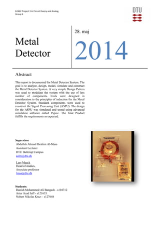
  • 11. 62462 Project 3 in Circuit theory and Analog Group 4 Note: For Schematics, Test Results and Block Diagram Of the system please refer to the appendices at the last part of the report 10 4 Conclusion Part Requirement Nr Description Mandatory / Optional State System R1 Test object: 5 crowns Mandatory Approved R2 Testing distance: 1 cm Mandatory Approved R3 Max output: 4.5 V - 5.5V Mandatory Approved R4 Min output: 0 V - 0.5 V Mandatory Approved R5 Peak to peak: <20 mV Mandatory Approved Transducer R6 Operating value: 10 kHz Mandatory Approved R7 Min output: ~ 0 Max output: 0 < Mandatory Approved R8 Use of function generator Mandatory Approved R9 Handmade & calculations Mandatory Approved R10 Formulas Mandatory Approved ASPU R11 Convert signal Mandatory Approved R12 3-dB bandwidth of max. 4 kHz Mandatory Approved Additional R13 Use of potentiometers or variable resistors Optional Rejected 4.1 Product Assessment The product ended up by fulfilling the expected requirements. Some of the major requirements are the rise and fall time, +-0,5v 5v output. Approximately zero at the input when no coin is available. The Image at the start page is the final prototype of the Metal Detector System. 4.2 Process Assessment It is always convenient to work with such a well-defined project who’s learning outcome is at its peak .It is always best to particulate according to the aspects of theory. We worked according to our time plan therefore we did not emerged with any major problems everything went very clearly though we had some issues but not any serious technical issues. Group work was outstanding gave us a good communication skills and understanding others work. Problem was modulated and was fairly fulfilled by the group members.
  • 12. 62462 Project 3 in Circuit theory and Analog Group 4 Note: For Schematics, Test Results and Block Diagram Of the system please refer to the appendices at the last part of the report 11 5 Appendixes 5.1 Appendix 1. (Schematics) 5.1.1 Amplifier Figure 5: Screen Shot shows the Amplification Circuit 5.1.2 Active Full Wave Precision Rectifier
  • 13. 62462 Project 3 in Circuit theory and Analog Group 4 Note: For Schematics, Test Results and Block Diagram Of the system please refer to the appendices at the last part of the report 12 Figure 6: Screen Shot shows the Full Wave Rectifier (active) 5.1.3 Active Low Pass Filters In Cascade Figure 7: Screen Shot shows the Low Pass Filters in Cascade 5.1.4 Full System Schematic Figure 8: Screen Shot shows the Schematic of the Whole System
  • 14. 62462 Project 3 in Circuit theory and Analog Group 4 Note: For Schematics, Test Results and Block Diagram Of the system please refer to the appendices at the last part of the report 13 5.2 Appendix 2. (Transducer Test) Figure 9: Screenshot of transducer test when no coin in there Figure 10: Screenshot of the transducer test when coin is introduced
  • 15. 62462 Project 3 in Circuit theory and Analog Group 4 Note: For Schematics, Test Results and Block Diagram Of the system please refer to the appendices at the last part of the report 14 5.3 Appendix 3. (ASPU Tests) Figure 11: Screenshot of the Amplification test Figure 12: Screenshot of the half wave rectification test
  • 16. 62462 Project 3 in Circuit theory and Analog Group 4 Note: For Schematics, Test Results and Block Diagram Of the system please refer to the appendices at the last part of the report 15 Figure 13: Screenshot of the full wave rectification test 5.4 Metal Detector Test Figure 14: Screenshot of Metal Detector when idle
  • 17. 62462 Project 3 in Circuit theory and Analog Group 4 Note: For Schematics, Test Results and Block Diagram Of the system please refer to the appendices at the last part of the report 16 Figure 15: Screenshot Of the Metal Detector System when coin is introduced 5.5 Appendix 4. (Calculations) 5.5.1 Coil related calculations: To find the inductance this formula can be used: √ F = 10 kHz R = 4 ohm √ To find the number of turns of the coil this formula is used: ( )
  • 18. 62462 Project 3 in Circuit theory and Analog Group 4 Note: For Schematics, Test Results and Block Diagram Of the system please refer to the appendices at the last part of the report 17