1. Space Shift Keying in the Presence of
Multiple Co-Channel Interferers
by
Guriqbal Singh
A Thesis
Presented to Lakehead University
in Partial Fulfillment of the Requirement for the Degree of
Master of Science
in
Electrical and Computer Engineering
Thunder Bay, Ontario, Canada
Today’s Date
2. Abstract
Guriqbal Singh. Space Shift Keying Modulation in the Presence of Multiple Co-Channel
Interferers (Under the Supervision of Dr. Salama Ikki).
In this thesis, the performance of Space Shift Keying (SSK) Modulation, a technique for
Multiple Input Multiple Output (MIMO) wireless communication systems is studied. The results
are analyzed and compared assuming absence as well as presence of Co-Channel Interference
(CCI).
SSK Modulation is based on the concept of Spatial Modulation (SM) technique for MIMO
systems. In SM, only one transmitting antenna remains in the state of action at a single point
in time while others remain in sleep mode, resulting in no Inter Channel Interference (ICI). This
is another reason for the increase in system performance and spectral efficiency.
Unlike SM, in SSK Modulation there is no transmission of data symbols. However, the index
of transmitting antenna is transmitted, resulting in advantages such as a reduction in detection
complexity and hardware cost as there is no need for Amplitude Phase Modulation (APM)
elements at both transmitting and receiving end.
In this work, the exact analytical expression for Average Bit Error Rate (ABER) of SSK
Modulation in the presence of CCI has been derived, and the same is further supported by
MATLAB simulated results. The analysis with CCI is necessary because the spectral efficiency
of the communication system can be improved by a reduction in the re-use factor of the co-
channel; however, reducing the re-use factor also raises the co-channel interference.
Performance for the systems with single as well as multiple receiving antennas has been
analyzed twice considering correlated and uncorrelated Rayleigh fading channels. The asymptotic
analysis results for uncorrelated Rayleigh fading channels have also been derived and compared
with exact results.
3. Acknowledgments
First and foremost, my deepest appreciation goes to my supervisor - professor, Dr. Salama S. Ikki
(Faculty, Department of Electrical Engineering, Lakehead University). Dr. Ikki has continually
supported me and helped me in every step of the way. He gave me the motivation and the spirit
to help me achieve my goals. Without his guidance, I could not have completed this research.
I would also like to thank Mr. Raman Trivedi (DGM-R&D MicroMet-ATI Pvt. Ltd.) and Dr.
Eylem Erdogan. I am extremely grateful for their expertise, guidance and their encouragement
which they have given.
Furthermore, my special gratitude goes to the review committee, Dr. Ali Afana and Dr.
Dimiter Alexandrov for their feedback and approval of this research.
In addition, I would like to acknowledge my close friends; Simardeep Singh Gill and Kan-
warbir Singh Bajwa. During my research, I was able to get feedback and advice on my research
techniques or report writing. For motivation and support, I would like to recognize Jaspreet
Kaur Khela.
Moreover, I also thank my mother as she helped me on every step of my journey. Also, with
heavenly blessings of my father, I was able to complete this research.
Finally, I would like to sincerely thank all the faculty members of the Department of Elec-
trical Engineering at Lakehead University for their encouragement and help. I also would like to
extend my gratitude to all who helped me in one way or another.
Guriqbal Singh
gsingh9@lakeheadu.ca
i
6. List of Figures
1.1 Single Input Single Output System . . . . . . . . . . . . . . . . . . . . . . . . . . 4
1.2 Single Input Multiple Output System . . . . . . . . . . . . . . . . . . . . . . . . . 4
1.3 Multiple Input Single Output System . . . . . . . . . . . . . . . . . . . . . . . . . 4
1.4 Multiple Input Multiple Output System . . . . . . . . . . . . . . . . . . . . . . . 5
2.1 When transmitting data= 0, single receiving antenna . . . . . . . . . . . . . . . . 13
2.2 When transmitting data= 1, single receiving antenna . . . . . . . . . . . . . . . . 13
2.3 When transmitting data= 0, Multiple receiving antennas . . . . . . . . . . . . . . 15
2.4 When transmitting data= 1, Multiple receiving antennas . . . . . . . . . . . . . . 15
2.5 Block diagram of system with single receiving antenna used for simulation . . . . 16
2.6 Block diagram of system with multiple receiving antenna used for simulation . . . 16
2.7 Analytical, Simulation results of ABER versus SNR for SSK system with no CCI
over uncorrelated Rayleigh fading channels . . . . . . . . . . . . . . . . . . . . . . 22
2.8 Comparison of Asymptotic and Exact results of ABER versus SNR for SSK system
with no CCI over Uncorrelated Rayleigh fading channel . . . . . . . . . . . . . . . 24
2.9 Analytical, Simulation results of ABER versus SNR for SSK system with no in-
terference over Correlated Rayleigh fading channels . . . . . . . . . . . . . . . . . 27
2.10 Analytical, Simulation results of ABER versus SNR of SSK system with no inter-
ference over Uncorrelated Rayleigh fading channels . . . . . . . . . . . . . . . . . 32
2.11 Comparison of Asymptotic and Exact results of ABER v/s SNR for SSK system
with no interference over Uncorrelated Rayleigh channels . . . . . . . . . . . . . . 35
2.12 Analytical, Simulation results of ABER versus SNR for SSK system with no CCI
over correlated Rayleigh fading channels . . . . . . . . . . . . . . . . . . . . . . . 37
iv
7. 3.1 When transmitting data= 0, single receiving antenna in presence of CCI . . . . . 39
3.2 When transmitting data= 1, single receiving antenna in presence of CCI . . . . . 39
3.3 When transmitting data= 0, Multiple receiving antennas in presence of CCI . . . 40
3.4 When transmitting data= 1, Multiple receiving antennas in presence of CCI . . . 41
3.5 Block diagram of system with single receiving antenna used for simulation . . . . 41
3.6 Block diagram of system with multiple receiving antenna used for simulation . . . 42
3.7 Analytical, Simulation results of ABER versus SNR for SSK system with multiple
interferers over uncorrelated Rayleigh fading channels . . . . . . . . . . . . . . . . 46
3.8 Comparison of Asymptotic and Exact results of ABER v/s SNR for SSK system
in presence of CCI over Uncorrelated Rayleigh fading channels . . . . . . . . . . . 49
3.9 Analytical, Simulation results of ABER v/s SNR for SSK system with CCI over
Correlated Rayleigh fading channels . . . . . . . . . . . . . . . . . . . . . . . . . . 51
3.10 Analytical, Simulation results of ABER versus SNR for SSK system with multiple
interferers over uncorrelated Rayleigh fading channels . . . . . . . . . . . . . . . . 55
3.11 Comparison of Asymptotic and Exact results of ABER versus SNR for SSK system
in presence of CCI over Uncorrelated Rayleigh fading channels . . . . . . . . . . . 59
3.12 Analytical, Simulation results of ABER versus SNR for SSK system in presence
of interference over Correlated Rayleigh fading channels . . . . . . . . . . . . . . . 61
v
8. List of Tables
2.1 SSK Mapping for single receiving antenna . . . . . . . . . . . . . . . . . . . . . . 17
2.2 SSK Mapping for multiple receiving antennas . . . . . . . . . . . . . . . . . . . . 28
3.1 SSK Mapping for single receiving antenna with CCI . . . . . . . . . . . . . . . . . 43
3.2 SSK Mapping for multiple receiving antennas with CCI . . . . . . . . . . . . . . . 52
vi
9. List of Abbreviations
MIMO – Multiple Input Multiple Output.
SISO – Single Input Single Output.
ZF – Zero Forcing
SIMO – Single Input Single Output
MISO – Multiple Input Single Output
MRC – Maximul Ratio Combining
ML – Maximum Likelihood
VBLAST – Vertical Bell Laboratories Space Time
SMX – Spatial Multiplexing
SM – Spatial Modulation
SSK – Space Shift Keying
BPSK – Binary Phase Shift Keying
SNR – Signal to Noise Ratio
HYB – Hybrid
DIV – Diversity
BER – Bit Error Rate
BEP – Bit Error Probability
SER – Symbol Error Rate
SEP – Symbol Error Probability
ABER – Average Bit Eror Rate
ABEP – Average Bit Error Probability
AABER – Asymptotic Average Bit Error Rate
CBER – Conditional Bit Error Rate
CCI – Co-Channel Interference
PDF – Probability Density Function
10. Chapter 1
Introduction
1.1 Wireless Communication and Communication Systems
Wireless communication is one of the biggest gifts to mankind among technologies. Based
on the survey conducted by Statista, the number of users were exponentially increased from 4.01
billion to 4.43 billion over the years from 2013 to 2015, and are further expected to increase
up to 4.77 billion in 2017 [1]. The number of users and cellular data traffic are interdependent
where data traffic and the number of users are proportional. The increase in data traffic can
be explained because the users are extensively using e-books, Android/ Apple applications such
as social networking, video streaming, emails etc. Due to this increase of data traffic, mobile
operators are struggling to satisfy the users with a faster data rate [2].
Depending upon the number of antennas (antenna configuration) at the transmitting and
receiving ends, communication systems are divided into four categories: the single input single
output (SISO) systems, single input multiple output (SIMO) systems, multiple input single
output (MISO) systems, and multiple input multiple output (MIMO) systems. In SISO systems,
a single antenna is used at both transmitting and the receiving ends as shown in Fig. 1.1. In
SIMO systems, there is only one antenna at the transmitting end and multiple antennas at the
receiving end as shown in Fig. 1.2. In MISO systems, as shown in Fig. 1.3, there are multiple
antennas at the transmitting end but only one antenna at the receiving end. However, in MIMO
systems, as shown in Fig. 1.4., there are multiple antennas at both the transmitting as well as
11. CHAPTER 1. INTRODUCTION 3
the receiving ends.
Even though wireless communication provides countless benefits such as satellite commu-
nications or driver-less vehicles, there are many challenges to overcome. Each wireless system
suffers from the problems of the reliability of transmitted information, high-speed data transfer or
data rate and high spectral efficiency. Other problems include optimal data detection technique
with low complexity at low-cost [3], power-efficient data processing, signal fading, Co-Channel
Interference (CCI), and restricted availability of frequency spectrum.
It was shown that MIMO systems are an efficient solution to the above challenges by Fos-
chini et al. [4–6]. This study concluded that the asymptotic capacity of systems with multiple
antennas at the transmitting and receiving ends are linearly proportional to the transmitting
antennas under the effect of Rayleigh fading channels.
The multiple element antenna array set up in the MIMO system results in the capacity of
the system to be increased linearly with the increase in the number of antennas [3]. If the per-
formance of MIMO systems is compared with the performance of SISO systems, MIMO systems
offer high reliability of data transfer along with higher data rate [7]. For MIMO systems with a
small number of transmitting and receiving antennas, there was a linear increase in information-
theoretic capacity observed in scattering environments, at a high SNR (Signal to Noise Ratio) [8].
MIMO works on the principle of multiplexing multiple data symbols in space and transmitting
them without an increase in bandwidth. MIMO systems also reduce the effect of multi-path
fading. MIMO systems can be exploited in different ways to achieve the multiplexing gain of
an antenna array, but this is achieved at the cost of high complexity and at a high cost of im-
plementation [9]. MIMO systems are divided mainly into three sections: spatial multiplexing,
diversity transmission, and hybrid transmission.
In spatial multiplexing, multiple antenna arrays are used at the transmitting end to transmit
more information at a time. Vertical Bell Laboratory Layered Space Time (V-BLAST) is an
12. CHAPTER 1. INTRODUCTION 4
Figure 1.1: Single Input Single Output System
Figure 1.2: Single Input Multiple Output System
Figure 1.3: Multiple Input Single Output System
13. CHAPTER 1. INTRODUCTION 5
Figure 1.4: Multiple Input Multiple Output System
example of spatial multiplexing. V-BLAST is a layered structured data detection algorithm pro-
posed by Bell laboratories to exploit high spectral capacity offered by MIMO channels [4,10]. In
V-BLAST, multiple data symbols are multiplexed and transmitted at the same time over all the
channels without the need of an increase in bandwidth. At the detector location, data streams
are separated and detected using an interference elimination and combination of array processing
techniques.
In diversity transmission, multiple antennas are used to increase the reliability of informa-
tion. Alamouti scheme is an example of diversity transmission [11], in which two transmitting
antennas are used in order to obtain diversity at the transmitting end. The drawback of in-
creasing the system diversity is that with the increase in diversity there is a decrease in spectral
efficiency, which does not change in SIMO systems [12]. Researchers have overcome this problem
by adding a third section to the MIMO systems, which is named hybrid multiple input multiple
output (HYB MIMO) systems.
HYB MIMO system is the combination of both a spatial multiplexing technique and a di-
versity transmission technique. HYB MIMO system is a multi-layered space-time coding system
14. CHAPTER 1. INTRODUCTION 6
that provides diversity gain along with the increase in spectral efficiency [13].
1.2 Spatial Modulation Technique for MIMO Systems
SM is one of the MIMO system techniques in which SSK is used along with the amplitude
phase modulation to transfer data symbols over the MIMO channels [14]. SM and SSK entirely
avoids Inter Channel Interference and attains high Spectral efficiency at low system complexity
and low implementation cost, without requiring antenna synchronization at transmitting end
[9,15].
Using a SM technique, Spectral efficiency shows a rise by logarithm to the base two of the
number of transmitting antennas (log2Nt, where Nt is the number of transmitting antennas) as
compared to SISO system [16]. If compared with other MIMO techniques like Vertical Bell Lab-
oratory Layered Space-Time and Space-time Coding (STC), SM has higher error performance
with a moderate number of transmitting antennas [17].
In SM, the information is modulated by activating a single transmitting antenna at a time
(i.e. in each time slot) while keeping other transmitting antennas in a sleep state, which results
in the elimination of inter-channel interference along with the achievement of high multiplexing
gain [9,18]. As only one antenna is being used at a single point in time, this requires only one
Radio Frequency (RF) chain, which reduces the hardware cost and signal processing power of
the system [16]. Activating a single antenna at each time reduces the complexity of the system
without reducing data rate and system performance [18]. Also, in SM there is no requirement
for time synchronization between antennas [15,19].
In SM, information data are mapped with an antenna index of the active transmitting an-
tenna to be used for transmission [9]. In SM, the receiver part is designed using a Maximum
Likelihood (ML) detection technique for the estimation of transmitted data as well as the index
of active transmitting antenna from which the received data were transmitted [20]. The ML
detector is considered as an optimal detector for MIMO systems to minimize the Average Error
15. CHAPTER 1. INTRODUCTION 7
Probability(AEP) [21].
ML detector offers very low complexity and works on the principle of minimizing the Eu-
clidean distance to the receive vector [22]. ML detector performs a search operation on all the
received combinations of data and selects the best-related data. As in SM, there is activation
of one antenna at a single point in time, so the complexity of the ML detector decreases as
compared to the complexity of other detection techniques used in MIMO systems. For MIMO
SM the complexity of the ML detector is shown to be identical to the complexity for SIMO system.
SM is shown to be a better technique for implementation in large MIMO systems [23–26].
The high increase in data traffic has focused researchers on using a large number of antennas;
i.e.; tens to hundreds of antennas at both transmitting and receiving ends. This technique is
termed Large MIMO or Massive MIMO; [27–31] shows the growth in data rate and improved
Bit Error Rate (BER) performance of large MIMO systems.
1.3 Problem Statement, Relevant Works and Motivation
There are several types of digital communication systems, but almost each of the commu-
nication system needs a physical channel to transmit data, and these physical channels are not
only subjected to noise but also to fading. Multi-path fading is commonly observed in wireless
communication systems, which occurs because of constructive and destructive multi-paths re-
ceived with delays and attenuation. Rayleigh distribution is one of the very common multi-path
fading models with no line of sight.
Besides fading, Inter User Interference (Interference from other users) plays an important
role to degrade the performance of wireless systems. Wireless signals are more severely sub-
jected to Interference because of more base stations and mobile users. One of the main kinds of
interference is Co-channel Interference (CCI), which is produced due to the frequency re-use.
Many researchers have studied and analyzed the performance of SSK, SM in the presence
16. CHAPTER 1. INTRODUCTION 8
of different types of fading channels with perfect/ imperfect Channel State Information(CSI) or
channel estimation. The works in [26,33,39] showed that the performance of SSK is better than
many other conventional techniques of modulation.
By computing the Outage error probability and Shannon capacity of SM in the presence of
Rayleigh fading channels, M. M Ulla Faiz et al. in [34] have developed an information theoretic
framework. When compared to space-time block coding, the framework shows that SM provides
the increase in capacity on increasing the number of transmitting antennas.
The authors in [19,32,35], have studied the Average Bit Error Probability (ABEP) for SM
in a presence of Rayleigh fading channels. Researchers have analyzed Symbol Error Probability
of SM for a suboptimal receiver in [19] and have clearly shown that, as compared to V- BLAST
and Alamouti scheme, SM provides better performance along with low detection complexity and
the same spectral efficiency. In [32], the authors have derived closed form expression for ABEP
for SM using optimal detection technique at the receiver. In [35], the authors derived the upper
bound closed form expression for ABER of SM in the presence of correlated Rayleigh fading
channel.
The authors of [12] have provided detailed analysis for the performance of coded-SSK and
have derived closed form upper bound expression for Bit Error Probability (BEP) of SSK. The
authors have observed that SSK provides gain over the Amplitude Pulse Modulation (APM),
demonstrating that coded-SSK provides more capacity over APM.
In the presence of correlated Rician fading channels, the performance of SK has been ana-
lyzed in [36]. Marco Di Renzo et. al. in [36] proposed a general framework for the calculation of
ABEP, considering the random number of receiving antennas and two transmitting antennas in
the presence of arbitrary independent co-relation and channel coefficients of Rician fading chan-
nels. In [37] and [38], the authors have derived closed form exact and asymptotic upper bound
expressions for ABER of SM, SSK in the presence of correlated Nakagami-m fading channels.
17. CHAPTER 1. INTRODUCTION 9
In all of the above-mentioned studies, the perfect CSI is considered whereas in [39] and [40],
the authors have assumed imperfect CSI at receiver. In [39], Salama S. Ikki et al. have obtained
an exact closed form and asymptotic expressions for ABEP of SSK, using the ML detection tech-
nique at receiver, in the presence of Rayleigh fading channels. In [40], the authors have studied
through Monte Carlo simulations, and have shown that as compared to other techniques, SM is
more robust to channel estimation error.
These works have improved an understanding of SSK. Motivated by the various benefits of
using SSK and SM for MIMO systems and recent works on SSK have pushed an interest to
analyze the performance of SSK in the presence of CCI. To study the effect of CCI is of major
importance because spectral efficiency can be raised by decreasing the re-use factor of the co-
channel but this also raises CCI [41].
1.4 Thesis Contribution
1. In this thesis, exact expressions for ABER have been derived using ML detection technique
and the performance of SSK in the presence of multiple co-channel interferers has been an-
alyzed for a system with a single receiving antenna. The results are derived and analyzed,
assuming that the perfect CSI is available. The exact expression of ABER has been derived
for two cases, a) when the fading channels are uncorrelated, and b) when the fading chan-
nels are correlated. In this thesis, ABER is used as a performance parameter to analyze
the performance of system because its is considered as the most enlightening illustrator of
the performance of the system. ABER can be derived by averaging Conditional Bit Error
Rate (CBER) over fading statistics. The expression of asymptotic ABER has also been
derived, as this gives insight into the performance of the system at high Signal to Noise
Ratio (SNR). Furthermore, the mathematically derived results have also been verified by
comparing with simulations developed in MATLAB.
18. CHAPTER 1. INTRODUCTION 10
2. The exact and asymptotic expressions of ABER have been generalized for the system
with an arbitrary number of multiple receiving antennas using Maximum Ratio Combining
(MRC) based ML detector. MRC is an optimal receiver diversity combining technique for
noise limited systems. MRC improves the reliability and performance of transmission in
flat fading channels. In MRC, each received signal after being multiplied with weight, is
linearly added to another. The weights are chosen in such a way that the output SNR of
the combiner or adder should be maximum (weights are the conjugate of fading channel
coefficients) [46,47]. When the power of the noise at all antennas is the same, the weight
vector is the desired user’s channel vector. Throughout the analysis in this thesis, the same
noise power at all the branches is assumed. Moreover, the mathematically derived results
have also been compared with MATLAB simulations in order to justify the accuracy of
results.
1.5 Thesis Outline
The rest of thesis has been organized as follows:
In Chapter 2, two system models of SSK have been analyzed. Firstly, the system model with
two antennas at transmitting end and one antenna at receiving end is studied. Secondly, the
system model with two transmitting and an arbitrary number of Nr (multiple) receiving antennas
is studied. For both the systems, mathematically derived exact analytical expressions for ABER
in the absence of CCI are provided, assuming two different conditions. In the first condition,
zero correlation in fading channels (uncorrelated fading channels) is assumed and in the second
condition, correlated fading channels are assumed. Moreover, MATLAB based simulation results
are provided in order to support the accuracy of theoretical results. In this chapter, asymptotic
analysis has also been provided for both the system models.
In Chapter 3, the detailed mathematical analysis has been provided to calculate the exact
expressions of ABER for both systems mentioned in Chapter 2, with and without correlation
in fading channels. Also, the asymptotic ABER expressions for both the systems are derived.
19. CHAPTER 1. INTRODUCTION 11
Whereas in chapter 2 no CCI is assumed, in Chapter 3, it is assumed that the receiving anten-
nas are subjected to Gaussian CCI. In this chapter also, the MATLAB simulation results are
provided to justify the accuracy of theoretical results.
In Chapter4, the conclusion is stated and the future applications of SSK Modulation are
highlighted.
20. Chapter 2
Space Shift Keying Modulation
SM was introduced by R. Mesleh [15,19] with the intention to avoid inter channel interference
(ICI), to get rid of inter-antenna synchronization(IAS), to reduce system complexity, to enhance
spectral efficiency of MIMO systems as compared to the other MIMO techniques.
SSK Modulation is the special case of SM, in which only the antenna indices are transmitted
to relay the information; the data symbols are not transmitted. As in SSK Modulation data
symbols are not transmitted; therefore, there is no need of transceiver elements for the trans-
mission and detection of APM (Amplitude/Phase Modulation). As compared to SM, SSK offers
less detection complexity.
2.1 System Model
2.1.1 Single Receiving Antenna
Shown in Fig. 2.1 and 2.2 is the first system, where two transmitting antennas and the single
receiving antenna are considered. In SSK, only one transmitting antenna is in a state of action
at a single point in time, resulting in the need for only one RF chain. Fig. 2.1 refers to the time
instance when 0 is the data to be transmitted; therefore, transmitting antenna Tx1 is in active
mode and Tx2 is in sleep mode. Similarly, Fig. 2.2 shows the time instance when 1 is the data
to be transmitted; thus, transmitting antenna Tx2 is in active mode and Tx1 is in sleep mode.
21. CHAPTER 2. SPACE SHIFT KEYING MODULATION 13
Figure 2.1: When transmitting data= 0, single receiving antenna
Figure 2.2: When transmitting data= 1, single receiving antenna
22. CHAPTER 2. SPACE SHIFT KEYING MODULATION 14
2.1.2 Multiple Receiving Antennas
Figures 2.3 and 2.4 show the second system, where two transmitting antennas and Nr (mul-
tiple) receiving antennas are considered. In this system, MRC is used as the diversity combining
scheme. Figures 2.3 and 2.4 give an idea of the working of transmitting antennas. Fig. 2.3
tells about the system when 0 is the data to be transmitted, which causes the activation of
transmitting antenna Tx1 and deactivation of Tx2; therefore, Tx 1 is sending data to all the
receiving antennas. Similarly, Fig. 2.4 shows the system at a time when transmitting antenna
Tx2 is in active mode and Tx1 is in sleep mode; this happens when 1 is the data to be transmitted.
2.2 System Model for Simulation
2.2.1 Single Receiving Antenna
Figure 2.5 shows the system model with single receiving antenna developed for the simulations
in MATLAB.
2.2.2 Multiple Receiving Antennas
Figure 2.6 shows the system model with multiple receiving antennas developed for the sim-
ulations in MATLAB.
2.3 Performance Analysis for Single Receiving Antenna with Perfect CSI and no
Co-channel Interferer
2.3.1 Exact Analysis in Presence of Uncorrelated Rayleigh Fading Channels
Transmission and Reception
The received signal at the receiving end can be written as
y =
√
Ehj + n, j = 1, 2, (2.1)
where,
√
E is the energy of desired signal, hj is the complex Gaussian Rayleigh fading channel
of activated transmitting antenna with mean zero and variance 1, hj ∼ CN (0, 1) and n is the
complex Gaussian white noise with mean 0 and variance N0, n ∼ CN (0, N0).
23. CHAPTER 2. SPACE SHIFT KEYING MODULATION 15
Figure 2.3: When transmitting data= 0, Multiple receiving antennas
Figure 2.4: When transmitting data= 1, Multiple receiving antennas
24. CHAPTER 2. SPACE SHIFT KEYING MODULATION 16
Figure 2.5: Block diagram of system with single receiving antenna used for simulation
Figure 2.6: Block diagram of system with multiple receiving antenna used for simulation
25. CHAPTER 2. SPACE SHIFT KEYING MODULATION 17
As shown in the first system model, two transmitting antennas and one receiving antenna
have been considered. Therefore, to transmit symbol 0, Tx1 (Transmitting antenna 1) is ac-
tivated and to transmit symbol 1, Tx2 (Transmitting antenna 2) is activated. When there is
activation of Tx1, the received signal is written as, y1 =
√
Eh1 + n and when there is activation
of Tx2, the received signal is written as, y2 =
√
Eh2 + n.
Table 2.1: SSK Mapping for single receiving antenna
symbol Tx activated Received Signal
0 1 y1 =
√
Eh1 + n
1 2 y2 =
√
Eh2 + n
Detection
For the detection of transmitted signal, ML detector has been used, which is as written below
u = arg min
j=1,2
y −
√
Ehj
2
. (2.2)
Assuming that, the data symbol to be transmitted is 0, resulting in the activation of Tx1. The
received signal in this case can be written as
yr = y1 =
√
Eh1 + n. (2.3)
If y1 is the received signal, therefore, using ML detection method, the error can be defined as
Pe = Pr yr −
√
Eh1
2
> yr −
√
Eh2
2
, (2.4)
Pe = Pr 2
√
E {(h1 − h2) n∗
} >
√
E (h1 − h2)
2
,
Pe = Pr
√
E (h1 − h2)
2
< ˆn , (2.5)
where, ˆn = (2
√
E {(h1 − h2) n∗
}.
26. CHAPTER 2. SPACE SHIFT KEYING MODULATION 18
The variance of ˆn can be computed as, σ2
n = E (ˆn2
), where, E is an Expectation operator.
Therefore,
σ2
n = 4E
N0
2
|h1 − h2|2
= 2EN0 |h1 − h2|2
.
Hence, the Conditional Error Probability or Conditional Bit Error Rate (CBER) is defined as
Pr [n>a] = Q
a − µ
σ2
N
, (2.6)
where, µ is the mean which is assumed as zero,
Pe = Q
E |h1 − h2|2
2EN0 |h1 − h2|2
,
Pe = Q
E2 |h1 − h2|4
2EN0 |h1 − h2|2 ,
therefore, CBER can be computed as
Pe = Q
E |h1 − h2|2
2N0
= Q
E |H|2
2N0
, (2.7)
where, H = h1 − h2.
Now, CBER can be expressed in terms of γ as
Pe = Q (
√
γ) , (2.8)
where, γ = E|h1−h2|2
2N0
= E|H|2
2N0
, and Q (x) is a gaussian Q function defined as
Q(x) =
1
√
2π
∞
x
exp
−t2
2
dt. (2.9)
Probability Density Function (PDF)
The PDF of γ can be derived as follows
27. CHAPTER 2. SPACE SHIFT KEYING MODULATION 19
Firstly, the PDF of h is to be calculated, where, h = x + jy (x is the real part and y is the
imaginary part). Therefore, the joint PDF of x, y i.e fXY (x, y) can be written as
fXY (x, y) =
1
2πσ2
x
exp
−(x−m)2
2σ2
x
1
2πσ2
y
exp
−(y−m)2
2σ2
y , (2.10)
where, m is the mean, which has been considered zero for this analysis, m = 0 and σ2
is the
variance, which is considered equal for both x and y. Therefore, σ2
x = σ2
y = σ2
.
On substituting m = o, and σ2
x = σ2
y = σ2
in (2.10)
fXY (x, y) =
1
2πσ2
exp
−(x+y)2
2σ2
.
Now, converting the above equation to polar co-ordinates.
Assuming, a = |h| = x2 + y2 and θ = tan−1 y
x
, then,
fAθ(a, θ) =
1
2πσ2
exp
−a
2σ2
J(x,y),
where, J(x,y) is the Jacobian of x, y, which comes out to be J(x,y) = a. Therefore, the above
equation can be written as
fAθ(a, θ) =
a
2πσ2
exp
−a
2σ2
. (2.11)
From Eqn. (2.11), the individual PDF of fA(a) can be written as
fA(a) =
2π
0
a
2πσ2
exp
−a2
2σ2
dθ,
fA(a) =
a
σ2
exp
−a2
2σ2
.
The above equation can be written in terms of x as follows
fX(x) =
x
σ2
exp
−x2
2σ2
. (2.12)
As γ = E|h|2
2N0
. Therefore, applying the Cumulative Distribution Function (CDF)
FX(x) = Pr[X<x],
FX(x) = Pr
E |h|2
2N0
<x .
28. CHAPTER 2. SPACE SHIFT KEYING MODULATION 20
Let it be assumed that E
2N0
= d; therefore, FX(x) can be written as
FX(x) = Pr d |h|2
<x ,
FX(x) = Pr |h|2
<
x
d
. (2.13)
Equation 2.13, shows the expression of CDF, but we are interested in the PDF. Therefore, on
differentiating (2.13)
FX(x) =
1
2d x
d
fX(x)dx. (2.14)
On substituting, Eqn 2.12 in Eqn 2.14, the PDF can be written as
fX(x) = FX(x) =
1
Eσ2
N0
exp
−x
Eσ2
N0 ,
where Eσ2
N0
= ¯γ, therefore, PDF can further be computed as
fγ (x) =
1
¯γ
exp
−x
¯γ
. (2.15)
Average Bit Error Rate (ABER)
The ABER can be computed by averaging CBER given in (2.8) over the PDF of γ. Since H is
circularly symmetric, Gaussian distributed and γ is Rayleigh distributed. Subsequently, its PDF
can be written as
fγ (γ) =
1
¯γ
exp
−γ
¯γ
, (2.16)
where, ¯γ = E (γ) = E E|h1−h2|2
2N0
= E E|H|2
2N0
= Eσ2
N0
.
Average BER can be written as
ABER =
∞
0
Pe (γ) fγ (γ) dγ, (2.17)
where, Pe (γ) is given in (2.8) and fγ (γ) is given in (2.16). Therefore, substituting (2.8) and
(2.16) in (2.17), ABER can be written as
ABER =
∞
0
Q (
√
γ)
1
¯γ
exp
−γ
¯γ
dγ. (2.18)
29. CHAPTER 2. SPACE SHIFT KEYING MODULATION 21
On integrating (2.18), ABER can further be computed as
ABER =
1
2
1 −
¯γ/2
1 + ¯γ/2
,
ABER =
1
2
1 −
¯γ
2 + ¯γ
. (2.19)
Simulation Results
In this section, MATLAB simulated result for ABER performance of SSK with perfect channel
estimation and without any CCI for single receiving antenna are presented. In the simulation
at least 106
channel realizations over the uncorrelated Rayleigh fading channel are considered.
Furthermore, the simulation result is compared with the analytically derived result.
Fig. 2.7 shows the ABER versus SNR graph plotted for different values of SNR ranging from
0 dB to 30 dB. It can be clearly seen in the plot that simulation and analytical results are exactly
overlapping each other, which indicates the accuracy of results. The graph depicts that as SNR
increases, the ABER decreases, thus providing increase in the performance.
2.3.2 Asymptotic Analysis in Presence of Uncorrelated Rayleigh Fading Channels
By using the PDF given in (2.16), it is possible to numerically evaluate the system per-
formance. However, these evaluations do not offer insight into how the system parameters are
affected. Based on [56] and [42], the error probability in the fading channels depend on how the
behavior of PDF is at the output SNR. It is seen that as SNR takes on larger values, the behavior
of PDF becomes more irrelevant. This is due to the Q function approaching zero quickly, thus
making the integrand almost null over the given integration range. But still, the behavior of
PDF around zero is important since Q(0) = 1/2. The Taylor series can properly approximate
this behavior and in general, the terms obtained from the Taylor series are easier to manipulate.
Generally, for any large value of SNR, the PDF can be accurately approximated to the first term
of Taylor series since the other terms are near zero. These arguments have been recognized by
[56] and [42]. The approximate PDF of effective total SINR at the destination of the system is
determined in this section by applying the Taylor series as in [57,58].
30. CHAPTER 2. SPACE SHIFT KEYING MODULATION 22
0 5 10 15 20 25 30
Signal to Noise Ratio
10-4
10-3
10-2
10-1
100
AverageBitErrorRate(ABER)
Theoretical
Simulation
Figure 2.7: Analytical, Simulation results of ABER versus SNR for SSK system with no CCI over
uncorrelated Rayleigh fading channels
31. CHAPTER 2. SPACE SHIFT KEYING MODULATION 23
From eqn. 2.15 and 2.16, the PDF can be written as
fγ(γ) =
1
¯γ
exp
−γ
¯γ
,
where ¯γ = E (γ) = E E|h1−h2|2
2N0
= E E|H|2
2N0
= Eσ2
N0
.
Applying Taylor series expansion, the PDF can be written as
fγ(γ) =
1
¯γ
+ HOT, (2.20)
where, HOT refers to the Higher Order Terms.
Asymptotic ABER
Using the equation of ABER given in equation 2.17
ABER =
∞
0
Pe (γ) fγ (γ) dγ, (2.21)
where, Pe (γ) is given in (2.8) and fγ (γ) is given in (2.20). Hence, neglecting the Higher Order
Term of (2.20), asymptotic ABER can be written as:
AABER
∞
0
Q (
√
γ)
1
¯γ
dγ, (2.22)
AABER
1
¯γ
∞
0
Q (
√
γ) dγ.
On integrating the above equation Asymptotic ABER can be computed as
AABER
1
2¯γ
. (2.23)
Simulation Results
In this section, a comparison of exact theoretical and simulation ABER result with the asymp-
totic ABER result is provided. Asymptotic result is an approximate result which provides an
idea of performance at high SNR.
32. CHAPTER 2. SPACE SHIFT KEYING MODULATION 24
It can be observed from Fig. 2.8 that the asymptotic result exactly overlaps the exact results
in the region of high SNR. Therefore, asymptotic result is more tight at high SNR
0 5 10 15 20 25 30
Signal to Noise Ratio
10-4
10-3
10-2
10-1
100
AverageBitErrorRate(ABER)
Theoretical
Simulation
Asymptotic
Figure 2.8: Comparison of Asymptotic and Exact results of ABER versus SNR for SSK system with no
CCI over Uncorrelated Rayleigh fading channel
2.3.3 Exact Analysis in Presence of Correlated Rayleigh Fading Channels
In sections 2.3.1 and 2.3.2, it is assumed that fading channels are independent of each other.
As the variance of h1 = 1 and the variance of h2 = 1, the resulting variance of h1 − h2 = 2.
However, in this section, fading channels are assumed dependent on each other; in other words,
33. CHAPTER 2. SPACE SHIFT KEYING MODULATION 25
fading channels are correlated, with the resulting variance of h1 − h2 = 2.
The above-mentioned condition is commonly to be found in practical communication sys-
tems, especially in MIMO systems. Fading Correlation is caused due to the inadequate distance
between the antennas, mainly in compact sized devices equipped with space-antenna diversity.
It is important to analyze the performance of a system in the presence of Correlated Fading
Channels because due to fading correlation, maximum diversity gain cannot be achieved.
In this section, the system as defined in section 2.3.1 has been analyzed assuming, the pres-
ence of Correlated Rayleigh fading channels, where ρ is the correlation coefficient.
Using the Eqn. 2.7 for CBER
Pe = Q
E |h1 − h2|2
2N0
= Q
E |H|2
2N0
,
where, H = h1 − h2.
Similar to (2.8) CBER can be expressed in terms of γc
Pe = Q (
√
γc) ,
where, γc = E|h1−h2|2
2N0
. Using Eqn. 2.16 for the PDF
fγc (γc) =
1
¯γc
exp
−γc
¯γc
,
where, ¯γc = E (γc) = E E|h1−h2|2
2N0
= E E|H|2
2N0
= Eσ2
N0
(1 − ρ),
where, ρ is the coefficient of Correlation between fading channels and σ2
is the variance of each
fading channel; therefore, σ2
= 1.
34. CHAPTER 2. SPACE SHIFT KEYING MODULATION 26
Average Bit Error Rate (ABER)
ABER can be written as given (2.17)
ABER =
∞
0
Pe (γc) fγc (γc) dγc
ABER =
∞
0
Q (
√
γc)
1
¯γc
exp
−γc
¯γc
dγc. (2.24)
ABER can be computed as
ABER =
1
2
1 −
¯γc/2
1 + ¯γc/2
=
1
2
1 −
¯γc
2 + ¯γc
, (2.25)
where, ¯γc = E
N0
(1 − ρ).
Simulation Results
In this section, MATLAB simulated results for exact ABER performance of SSK in the pres-
ence of Correlated Rayleigh Fading Channels are provided. The results for different values of
correlation coefficient (ρ) are provided in order to study the effect of fading correlation on the
performance of the system.
Fig. 2.9 demonstrates that the fading correlation and ABER are directly proportional. As
the value of correlation coefficient increases, the performance decreases. It can be noted from
the figure that, for ρ = 0 i.e when there is no correlation between fading channels or they are
completely independent, the ABER of 10−2
is obtained at SNR = 17dB, and for ρ = 0.3, the
ABER of 10−2
is achieved at SNR = 18dB, which shows the loss of 1dB. However, on further
increasing the value of ρ to 0.6 and 0.9, the ABER of 10−2
is achieved at SNR of 21dB and 27dB,
thus showing the loss by 4dB and 10dB respectively.
35. CHAPTER 2. SPACE SHIFT KEYING MODULATION 27
0 5 10 15 20 25 30
Signal to Noise Ratio
10-4
10-3
10-2
10-1
100
AverageBitErrorRate(ABER)
Theoretical
Simulation
; = 0.3
; = 0.6
; = 0
; = 0.9
Figure 2.9: Analytical, Simulation results of ABER versus SNR for SSK system with no interference
over Correlated Rayleigh fading channels
36. CHAPTER 2. SPACE SHIFT KEYING MODULATION 28
2.4 Performance Analysis for Multiple Receiving Antenna with Perfect CSI and
no Co-channel Interferer
2.4.1 Exact Analysis in Presence of Uncorrelated Rayleigh Fading Channels
Transmission and Reception
In this section, performance analysis for a system with multiple receiving antennas has been
studied, using MRC based ML detector.
The received signal at receiving end can be written as
yr =
√
Ehr,t + nr, t = 1, 2, (2.26)
where, r is the receiving antenna, t is the transmitting antenna,
√
E is the energy of desired
signal, hr,t is the complex Gaussian Rayleigh fading channel of activated transmitting antenna
and rth
receiving antenna with mean zero and variance 1, hr,t ∼ CN (0, 1) and n is complex
Gaussian white noise with mean 0 and variance N0, n ∼ CN (0, N0).
As shown in the second model, two transmitting antennas and Nr receiving antennas has
been considered. Therefore, to transmit symbol 0, Tx1 (Transmitting antenna 1) is activated
and to transmit symbol 1, Tx2 (Transmitting antenna 2) is activated. On the activation of
Tx1, yr,1 =
√
Ehr,1 + nr, is received at the receiving antennas and on activation of Tx2,
yr,2 =
√
Ehr,2 + nr, is received at the receiving antennas.
Table 2.2: SSK Mapping for multiple receiving antennas
symbol Tx activated Received Signal at rth Receive Antenna
0 1 yr,1 =
√
Ehr,1 + nr
1 2 yr,2 =
√
Ehr,2 + nr
37. CHAPTER 2. SPACE SHIFT KEYING MODULATION 29
Detection
ML detector, used for the detection of transmitted signal is defined as
u = arg min
t=1,2
Nr
r=1
yr −
√
Ehr,t
2
. (2.27)
Assuming that 0 is the symbol to be transmitted, resulting in the activation of Tx1. In this case,
received signal at the rth
antenna can be written as
yr =
√
Ehr,1 + nr. (2.28)
As, y1 is the received signal, therefore, using ML detection method, the error can be defined as
Pe = Pr
Nr
r=0
y1 −
√
Ehr,1
2
>
Nr
r=0
y1 −
√
Ehr,2
2
, (2.29)
Pe = Pr 2
√
E
Nr
r=0
(hr,1 − hr,2) n∗
r >
Nr
r=0
√
E (hr,1 − hr,2)
2
,
Pe = Pr
Nr
r=0
√
E (hr,1 − hr,2)
2
< ˆn , (2.30)
where ˆn = 2
√
E Nr
r=0 (hr,1 − hr,2) n∗
r .
The variance of ˆn can be computed as, σ2
n = E (ˆn2
), where E is an Expectation operator.
Therefore,
σ2
n = 4E
N0
2
Nr
r=0
|hr,1 − hr,2|2
,
σ2
n = 2EN0
Nr
r=0
|hr,1 − hr,2|2
.
Hence, the Conditional Error Probability is defined as
Pr [n>a] = Q
a − µ
σ2
N
, (2.31)
38. CHAPTER 2. SPACE SHIFT KEYING MODULATION 30
where, µ is the mean which is assumed as zero.
Pe = Q
Nr
r=0 E |hr,1 − hr,2|2
Nr
r=0 2EN0 |hr,1 − hr,2|2
,
Pe = Q
Nr
r=0 E2 |hr,1 − hr,2|4
2EN0
Nr
r=0 |hr,1 − hr,2|2
. (2.32)
Therefore, CBER be written as
Pe = Q
Nr
r=0 E |hr,1 − hr,2|2
2N0
, (2.33)
Now, CBER can be expressed in terms of γr as
Pe = Q (
√
γr) , (2.34)
where, γr =
Nr
r=0 E|hr,1−hr,2|2
2N0
, and Q (x) is a gaussian Q function defined in (2.9) as
Q(x) =
1
√
2π
∞
x
exp
−t2
2
dt. (2.35)
Probability Density Function (PDF)
The PDF of γr can be written by using [43, 14-4-13] as
fγr (γr) =
1
(Nr − 1)!
1
¯γr
Nr
γNr−1
r exp
−γr
¯γr
, (2.36)
where ¯γr = E (γr) = E
Nr
r=0 E|hr,1−hr,2|2
2N0
.
Average Bit Error Rate (ABER)
The ABER can be computed by averaging CBER in (2.34) over the PDF of γr given in (2.36).
Hence, the ABER can be computed as in (2.17). Therefore, substituting (2.34) and (2.36)
in (2.17) ABER can be written as
ABER =
∞
0
Q (
√
γr)
1
(Nr − 1)!
1
¯γr
Nr
γNr−1
r exp
−γr
¯γr
dγr, (2.37)
ABER = γNr
a
Nr−1
k=0
Nr − 1 + k
k
[1 − γa]k
, (2.38)
where γa = 1
2
1 − ¯γb/2
1+ ¯γb/2
= 1
2
1 − ¯γb
2+ ¯γb
, where ¯γb = ¯γr
Nr
.
39. CHAPTER 2. SPACE SHIFT KEYING MODULATION 31
Simulation Results
In this section, the MATLAB simulated result for ABER performance of SSK without any CCI
for multiple receiving antennas has been provided. At least 106
channel realizations over the
Rayleigh fading channel are considered for this simulation. Furthermore, simulation and analyt-
ically derived results are compared.
Fig. 2.10 shows the ABER versus SNR plot for different values of SNR ranging from 0 dB to
30 dB. This figure is plotted for the variable number of receiving antennas, varying from Nr = 1
to Nr = 5, in order to study the effects of increase/decrease in the number of receiving antennas
or the receive diversity. It can be seen that the simulated and analytical results are similar,
which is the evidence for the accuracy of the theoretical result. The graph depicts that as SNR
increases, the average bit error rate decreases, thus giving an increase in performance. Also, on
an increase in the number of receiving antennas, a decrease in ABER is observed, resulting in
better performance. It can be said that with more receiving antennas, the less signal power is
needed for high performance. It is observed from the figure that, to obtain the ABER of 10−3
,
different SNR is needed, depending on the number of receiving antennas in the system.
In the case of 1 receiving antenna; i.e., if Nr = 1, there is a need for around 27dB of SNR
to obtain ABER of 10−3
dB. Whereas, in the case of Nr = 2 there is a need of around 14dB of
SNR, which shows a gain of 13dB. Similarly, if there are five receiving antennas, i.e., Nr = 5,
then 5.5dB of SNR is needed to obtain the ABER of 10−3
, which provides a gain of 27.5dB when
compared to the case of Nr = 1.
It is clearly visible from the figure 2.10 that, there is the biggest gap in the curve for Nr = 1
and Nr = 2, therefore, showing the significant increase in the performance. However, as the
value of Nr is increasing, the gap of the curve when compared with the curve of the adjacent
lower value of Nr goes on decreasing which shows that as we increase the number of antennas so
does the performance increases but the increase in performance is getting limited or the gain in
40. CHAPTER 2. SPACE SHIFT KEYING MODULATION 32
SNR is decreasing.
0 5 10 15 20 25 30
Signal to Noise Ratio
10-4
10-3
10-2
10-1
100
AverageBitErrorRate(ABER)
Theoretical
Simulation
Nr=5
Nr=4
Nr=3
Nr=2
Nr=1
Figure 2.10: Analytical, Simulation results of ABER versus SNR of SSK system with no interference
over Uncorrelated Rayleigh fading channels
2.4.2 Asymptotic Analysis in Presence of Uncorrelated Rayleigh Fading Channels
Using the Conditional Error Probability given in (2.33)
Pe = Q
Nr
r=0 E |hr,1 − hr,2|2
2N0
,
41. CHAPTER 2. SPACE SHIFT KEYING MODULATION 33
Similar to (2.34), above equation can further be expressed in terms of γr as
Pe = Q (
√
γr) , (2.39)
where γr =
Nr
r=0 E|hr,1−hr,2|2
2N0
.
Using the PDF given in (2.36)
fγr (γr) =
1
(Nr − 1)!
1
¯γr
Nr
γNr−1
r exp
−γr
¯γr
. (2.40)
On applying Taylor series expansion and similar to [39, 12], the above equation can be written
as
fγr (γr) =
1
(Nr − 1)!
1
¯γr
Nr
γNr−1
r + H.O.T, (2.41)
where H.O.T stands for Higher Order Terms and ¯γr = E (γr) = E
Nr
r=0 E|hr,1−hr,2|2
2N0
.
Asymptotic ABER
Now, Substituting (2.39) and the first term of (2.41) in (2.17), asymptotic ABER can be written
as
AABER =
∞
0
Q (
√
γr)
1
(Nr − 1)!
1
¯γr
Nr
γNr−1
r dγr.
On solving the integral, above equation can be computed as
AABER =
1
Nr!
1
¯γr
Nr
2(Nr−1)
Γ(Nr + 0.5)
√
π
= C
1
¯γr
Nr
, (2.42)
where C = 1
Nr!
2(Nr−1)Γ(Nr+0.5)
√
π
, is a constant. Beign a constant relying on the number of receiving
antennas Nr, 2.42 clearly indicates that the diversity order equal to the number of receiving
antennas Nr can be obtained.
Simulation Results
In this section, a plot showing the comparison of exact performance analysis with the asymptotic
analysis is provided. Asymptotic results are approximate results used to study the performance
42. CHAPTER 2. SPACE SHIFT KEYING MODULATION 34
of the system at high SNR. In Fig. 2.11, results are presented considering variable number of
number of receiving antennas, varying from Nr = 1 − 5.
It can be seen in the figure that, for Nr = 1 the asymptotic result starts overlapping the exact
result from SNR = 17dB, whereas, for Nr = 2 the results start overlapping from SNR= 20dB
which goes on increasing as there is an increase in the number of receiving antennas. Therefore,
it can be said that asymptotic result loses its tightness with increase in receive diversity.
2.4.3 Exact Analysis in Presence of Correlated Rayleigh Fading Channels
Using (2.33), the CBER can be written as
Pe = Q
Nr
r=0 E |hr,1 − hr,2|2
2N0
, (2.43)
Now, similar to (2.34), CBER can be expressed in terms of γrc as
Pe = Q (
√
γrc) , (2.44)
where γrc =
Nr
r=0 E|hr,1−hr,2|2
2N0
.
Using (2.36), PDF can be written as
fγrc (γrc) =
1
(Nr − 1)!
1
¯γrc
Nr
γNr−1
r exp
−γrc
¯γrc
, (2.45)
where, ¯γrc = E (γrc) = E
Nr
r=0 E|hr,1−hr,2|2
2N0
= NrEσ2
r
N0
(1 − ρr),
where, Nr is number of receiving antennas, σ2
r is the variance of each fading channel = 1, and ρr
is the correlation coefficient between fading channels.
43. CHAPTER 2. SPACE SHIFT KEYING MODULATION 35
0 5 10 15 20 25 30
Signal to Noise Ratio
10-4
10-3
10-2
10-1
100
AverageBitErrorRate(ABER)
Theoretical
Simulation
Asymptotic
Nr=4
Nr=5
Nr=1
Nr=2
Nr=3
Figure 2.11: Comparison of Asymptotic and Exact results of ABER v/s SNR for SSK system with no
interference over Uncorrelated Rayleigh channels
44. CHAPTER 2. SPACE SHIFT KEYING MODULATION 36
Average Bit Error Rate (ABER)
Using Eqn. 2.17 and similar to 2.37, the ABER can be computed by substituting 2.44 and 2.45
in 2.17
ABER =
∞
0
Q (
√
γrc)
1
(Nr − 1)!
1
¯γrc
Nr
γNr−1
rc exp
−γrc
¯γrc
dγrc,
ABER = γNr
ac
Nr−1
k=0
Nr − 1 + k
k
[1 − γac]k
, (2.46)
where, γac = 1
2
1 − ¯γbc/2
1+ ¯γbc/2
= 1
2
1 − ¯γbc
2+ ¯γbc
,
where, ¯γbc = ¯γrc
Nr
, and ¯γrc = NrE
N0
(1 − ρr) .
Simulation Results
In this section, MATLAB plotted simulation and analytical results for ABER in the presence
of correlated Rayleigh fading channels are presented. The results are provided by varying the
values of correlation coefficient for a different number of receiving antennas.
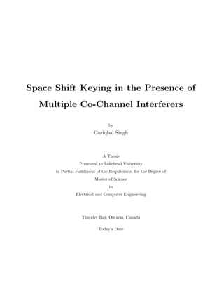
It can be seen in Fig. 2.12 that as the value of correlation coefficient increases, the perfor-
mance of the system decreases whereas the performance of the system is enhanced by increasing
number of receiving antennas. The results are provided assuming 1, 3, and 5 are the number
of receiving antennas with the correlation coefficient (ρ) = 0, 0.5 and 0.9 for each number of
receiving antennas.
As per the results illustrated in Fig. 2.12, it can be said that the system with Nr = 1 and
ρ = 0.9 is the system with the lowest performance among all the systems shown. However, the
system with Nr = 5 and ρ = 0 is the system with highest performance or with most efficiency
among all the systems shown.
It can be seen that for Nr = 5, on increasing the value of ρ the gap between curves is greater
as compared to the gap between the curves for Nr = 3. The least gap between the curves occurs
for Nr = 1. Therefore, it can be said that with an increase in the number of receiving antennas
45. CHAPTER 2. SPACE SHIFT KEYING MODULATION 37
the effect of correlation also increases. The figure also depicts that an effect of correlation also
increases with an increase in SNR, as the gap between the curves of different values of ρ keeps
on increasing with an increase in SNR for each value of Nr.
0 5 10 15 20 25 30
Signal to Noise Ratio
10-4
10-3
10-2
10-1
100
AverageBitErrorRate(ABER)
Theoretical
Simulation
Nr
= 1
Nr
= 3
Nr
= 5
; = 0.9
; = 0.5
; = 0
Figure 2.12: Analytical, Simulation results of ABER versus SNR for SSK system with no CCI over
correlated Rayleigh fading channels
46. Chapter 3
Space Shift Keying Modulation in
Presence of Multiple Co-Channel
Interferers
In this chapter, the performance of SSK Modulation in presence of multiple co-channel interferers
has been studied.
This chapter is divided into two sections. In the first section, performance is studied assuming
single receiving antenna and in the second section, multiple receiving antennas are assumed. In
both the sections, exact expressions for ABER over correlated and uncorrelated Rayleigh fading
channel using the ML detection method are derived. Also, the expressions for asymptotic ABER
are provided. Throughout the analysis, equal power multiple co-channel interferers are assumed.
3.1 System Model
3.1.1 Single Receiving Antenna
Shown in Fig. 3.1 an 3.2 is the first system with two transmitting antennas and a single
receiving antenna. Similarly, as mentioned before in chapter 2 section 2.1.1, that in SSK system
only one transmitting antenna is in a state of action at a time. Fig. 3.1 refers to the time instance,
when 0 is the data to be transmitted; therefore, transmitting antenna Tx1 is in active mode and
47. CHAPTER 3. SPACE SHIFT KEYING MODULATION IN PRESENCE OF MULTIPLE CO-CHANNEL
INTERFERERS 39
Tx2 is in sleep mode. Similarly, Fig. 3.2 shows the time instance, when 1 is the data to be
transmitted, therefore, transmitting antenna Tx2 is in active mode and Tx1 is in sleep mode. In
this system model, L equal power co-channel interferers are assumed to affect the received signal.
Figure 3.1: When transmitting data= 0, single receiving antenna in presence of CCI
Figure 3.2: When transmitting data= 1, single receiving antenna in presence of CCI
3.1.2 Multiple Receiving Antennas
The second system is shown in Fig. 3.3 and 3.4. In this system, two transmitting antennas
and Nr(multiple) receiving antennas are considered. In this system, MRC is used as diversity
combining scheme. These figures 3.3 and 3.4 gives an idea for the working of antennas. The
working of antennas is very similar to what was described in section 2.1.2. Fig. 3.3 shows the
48. CHAPTER 3. SPACE SHIFT KEYING MODULATION IN PRESENCE OF MULTIPLE CO-CHANNEL
INTERFERERS 40
time, when 0 is the data to be transmitted, which activates transmitting antenna Tx1 to transmit
data over all the receiving antennas, whereas, Tx2 is in sleep mode. Therefore, there is no data
transmission from Tx2. Similarly, Fig. 3.4 shows the time when transmitting antenna Tx2 is in
active mode and Tx1 is in sleep mode, and this happens when 1 is the data to be transmitted.
In both of these conditions each of the received signal is exposed to L equal power co-channel
interferers.
Figure 3.3: When transmitting data= 0, Multiple receiving antennas in presence of CCI
3.2 System Model for Simulation
3.2.1 Single Receiving Antenna
Figure 3.5 shows the system model with single receiving antenna developed for the simulations
in MATLAB.
3.2.2 Multiple Receiving Antennas
Figure 3.6 shows the system model with multiple receiving antennas developed for the sim-
ulations in MATLAB.
49. CHAPTER 3. SPACE SHIFT KEYING MODULATION IN PRESENCE OF MULTIPLE CO-CHANNEL
INTERFERERS 41
Figure 3.4: When transmitting data= 1, Multiple receiving antennas in presence of CCI
Figure 3.5: Block diagram of system with single receiving antenna used for simulation
50. CHAPTER 3. SPACE SHIFT KEYING MODULATION IN PRESENCE OF MULTIPLE CO-CHANNEL
INTERFERERS 42
Figure 3.6: Block diagram of system with multiple receiving antenna used for simulation
3.3 Performance Analysis for Single Receiving Antenna with Perfect CSI and Mul-
tiple Co-channel interferers
3.3.1 Exact Analysis in Presence of Uncorrelated Rayleigh Fading Channels
Transmission and Reception
The received signal at the receiving antenna is
y = Eshj +
L
k=1
Eikgk + w, j = 1, 2, (3.1)
where,
√
Es is the energy of desired signal,
√
Eik is the energy of kth
interfering user, w is the
complex Gaussian white noise, with mean zero and variance N0, N0 ∼ CN (0, N0) hj and gk are
the complex Gaussian Rayleigh fading channel of activated user antenna and the kth
interfering
user with mean zero and variance 1, hj ∼ CN (0, 1), gk ∼ CN (0, 1). Both hj and gk are consid-
ered mutually independent of each other. Perfect channel estimation is assumed at the receiving
end.
In first model, two transmitting antenna and one receiving antenna is considered. Therefore,
to transmit symbol 0, Tx1 is activated and to transmit symbol 1, Tx2 is activated and if data
is transmitted by Tx1 then, y1 =
√
Esh1 + L
k=1
√
Eikgk + w is the received signal and if data is
transmitted by Tx2 then, y2 =
√
Esh2 + L
k=1
√
Eikgk + w is the received signal.
51. CHAPTER 3. SPACE SHIFT KEYING MODULATION IN PRESENCE OF MULTIPLE CO-CHANNEL
INTERFERERS 43
Table 3.1: SSK Mapping for single receiving antenna with CCI
symbol Tx activated Received Signal
0 1 y1 =
√
Esh1 + L
k=1
√
Eikgk + w
1 2 y2 =
√
Esh2 + L
k=1
√
Eikgk + w
Detection
ML detector written below, has been used to detect the transmitted signal
u = arg min
j=1,2
y − Eshj . (3.2)
Assuming that the symbol to be transmitted is 0, resulting in the activation of Tx1, the received
signal in this case can be written as
yr = y1 = Esh1 +
L
k=1
Eikgk + w. (3.3)
In case, y1 is the received signal, therefore, using ML detection method, the error can be defined
as
Pe = Pr yr − Esh1
2
> yr − Esh2
2
, (3.4)
Pe = Pr 2 Es (h1 − h2) w∗
+ (h1 − h2)
L
k=1
Eikg∗
k > Es (h1 − h2)
2
,
Pe = Pr Es (h1 − h2)
2
< ˆw , (3.5)
where, ˆw = 2
√
Es (h1 − h2) w∗
+ (h1 − h2) L
k=1
√
Eikg∗
k .
The variance of ˆw can be computed as : σ2
w = E ( ˆw2
), where E is an Expectation operator.
Therefore,
σ2
w = 4Es |h1 − h2|2 N0
2
+
L
k=1
√
Eik |gk|2
2
,
σ2
w = 2Es |h1 − h2|2
N0 +
L
k=1
Eik |gk|2
.
52. CHAPTER 3. SPACE SHIFT KEYING MODULATION IN PRESENCE OF MULTIPLE CO-CHANNEL
INTERFERERS 44
Hence, using (2.6) CBER can be written as
Pe = Q
√
Es (h1 − h2)
2
2Es |h1 − h2|2
N0 + L
k=1
√
Eik |gk|2
,
Pe = Q
Es |h1 − h2|2
2 N0 + L
k=1 Eik |gk|2
. (3.6)
Using (12 − 17) of [44], (3.6) can be written as
Pe = Q
Es |h1 − h2|2
2 N0 + L
k=1 Ek
,
Pe = Q
Es
2N0
|h1 − h2|2
1 + L
k=1
Ek
N0
= Q
Es
2N0
|H|2
1 + L
k=1
Ek
N0
, (3.7)
where, H = h1 − h2, (3.7) can further be expressed in terms of γe
Pe = Q (
√
γe) , (3.8)
where, γe =
Es
2N0
|h1−h2|2
1+ L
k=1
Ek
N0
, and Q is defined in (2.9) .
Probability Density Function (PDF)
Since H is a circularly symmetric Gaussian distributed and γe is Rayleigh distributed, similar to
(2.16), the PDF can be written as
fγe (γe) =
1
¯γe
exp
−γe
¯γe
, (3.9)
where, ¯γe = E (γe) = E
Es
2N0
|h1−h2|2
1+ L
k=1
Ek
N0
.
Average Bit Error Rate (ABER)
The ABER can be computed by averaging CBER in (3.8) over the Probability Density Function
(PDF) of γe given in (3.9) .
ABER =
∞
0
Pe (γe) fγe (γe) dγe. (3.10)
53. CHAPTER 3. SPACE SHIFT KEYING MODULATION IN PRESENCE OF MULTIPLE CO-CHANNEL
INTERFERERS 45
Therefore, placing (3.8) and (3.9) in (3.10), ABER can be written as
ABER =
∞
0
Q (
√
γe)
1
¯γe
exp
−γe
¯γe
dγe. (3.11)
After solving the integral, ABER can be computed as
ABER =
1
2
1 −
¯γe/2
1 + ¯γe/2
,
ABER =
1
2
1 −
¯γe
2 + ¯γe
. (3.12)
Simulation Results
In this section, MATLAB simulated results for ABER performance of SSK with perfect channel
estimation and in the presence of CCI for the single receiving antenna are presented. For the
simulation, at least 106
channel realizations are considered over the uncorrelated Rayleigh fading
channel. Furthermore, simulated results are compared with the analytically derived result to
show the accuracy of the analytical result.
Figure 3.7, shows the ABER versus SNR graph for single receiving antenna. This graph has
been plotted by varying the number of interferers, ranging from L = 0 (no interference) to L =
5, in order to briefly analyze the effect of an increase in CCI on performance of the system.
It can be seen in the figure that, with the increase in the number of interferers, there is an
enhancement in ABER, i.e., as interfering users are increasing, the performance of the system
is degrading. When there is no interference (L = 0), ABER of 10−2
is observed at 17dB SNR.
Whereas, when L = 1, ABER of 10−2
is observed at 19dB SNR, which shows the loss by 2dB.
Furthermore, in the case of L = 2 the ABER of 10−2
is achieved at 29dB SNR, showing the loss
of 12dB as compared to ABER with no interference. Also, it can be clearly seen in the figure
that for all the cases when number of interferers are more than 2, i.e., L = 3, 4 or 5, the ABER
of 10−2
cannot be achieved till 30dB of SNR.
Figure 3.7 also illustrates that with the increase in SNR there is a rise in the performance,
54. CHAPTER 3. SPACE SHIFT KEYING MODULATION IN PRESENCE OF MULTIPLE CO-CHANNEL
INTERFERERS 46
0 5 10 15 20 25 30
Signal to Noise Ratio
10-4
10-3
10-2
10-1
100
AverageBitErrorRate(ABER)
Theoretical
Simulation
L=1
L=2
L=0
L=3
L=4
L=5
Figure 3.7: Analytical, Simulation results of ABER versus SNR for SSK system with multiple interferers
over uncorrelated Rayleigh fading channels
55. CHAPTER 3. SPACE SHIFT KEYING MODULATION IN PRESENCE OF MULTIPLE CO-CHANNEL
INTERFERERS 47
and at low SNR the performance for L = 1 to L = 5 is approximately equal. Moreover, with
the simultaneous increase in SNR and interference, there occurs an error floor, which can be
explained as when energy of desired signal and energy of the interference both increase simulta-
neously, the ABER gets independent of both, as energy of the desired signal and energy of the
interference cancel out each other.
3.3.2 Asymptotic Analysis in Presence of Uncorrelated Rayleigh Fading Channels
Using (3.9), the PDF can be written as
fγe (γe) =
1
¯γe
exp
−γe
¯γe
,
where ¯γe = E (γe) = E
Es
2N0
|h1−h2|2
1+ L
k=1
Ek
N0
.
Applying the Taylor series expansion, PDF can be written as
fγe (γe) =
1
Es
N0
1+ L
k=1 Ek
+ HOT, (3.13)
where HOT refers to the Higher Order Terms.
Asymptotic ABER
Using the equation of ABER given in (3.10)
ABER =
∞
0
Pe (γe) fγe (γe) dγe,
where Pe (γe) is given in (3.8) and fγe (γe) is given in (3.13). Hence, neglecting the Higher Order
Terms of (3.13), asymptotic ABER can be written as
AABER
∞
0
Q (
√
γe)
1
¯γe
dγe, (3.14)
AABER
1
¯γe
∞
0
Q (
√
γe) dγe.
On integrating the above equation asymptotic ABER can be computed as
AABER
1
2 ¯γe
=
1
2
Es
N0
1+ L
k=1
Ek
N0
(3.15)
56. CHAPTER 3. SPACE SHIFT KEYING MODULATION IN PRESENCE OF MULTIPLE CO-CHANNEL
INTERFERERS 48
Simulation Results
In this section, comparison of asymptotic and exact ABER results of the SSK Modulation com-
munication system in presence of CCI is provided.
It can be seen in Fig. 3.8 that asymptotic and exact results overlap each other or both are
exactly the same in the region of higher SNR. The results have been presented by varying the
number of cochannel interferers for the system with single receiving antenna.
It can be noticed from the figure that, for L=0, the asymptotic and exact results start over-
lapping from around SNR = 17dB. Whereas, for L = 1, they start overlapping around SNR=
25dB. However, for L = 3 and L = 4 they do not even overlap at SNR = 30dB, which shows
that the accuracy of asymptotic result keeps on decreasing with increase in interference; i.e., the
asymptotic result loses its tightness with the increase in number of interfering users.
3.3.3 Exact Analysis in Presence of Correlated Rayleigh Fading Channels
Using (3.6) and (3.7), CBER can be written as
Pe = Q
Es
2N0
|h1 − h2|2
1 + L
k=1
Ek
N0
= Q
Es
2N0
|H|2
1 + L
k=1
Ek
N0
,
where, H = h1 − h2, similar to (3.8) the above Eqn. can further be expressed in terms of γec.
Pe = Q (
√
γec) ,
where, γec =
Es
2N0
|h1−h2|2
1+ L
k=1
Ek
N0
and Q function is given in (2.9).
Using (3.9), PDF can be written as
fγec (γec) =
1
¯γec
exp
−γec
¯γec
,
where, ¯γec = E (γec) = E
Es
2N0
|h1−h2|2
1+ L
k=1
Ek
N0
=
Esσ2(1−ρ)
N0
1+L
Ek
N0
,
where, σ2
is the variance of each fading channel = 1 and ρ is the correlation coefficient between
fading channels.
57. CHAPTER 3. SPACE SHIFT KEYING MODULATION IN PRESENCE OF MULTIPLE CO-CHANNEL
INTERFERERS 49
0 5 10 15 20 25 30
Signal to Noise Ratio
10-4
10-3
10-2
10-1
100
AverageBitErrorRate(ABER)
Theoretical
Simulation
Asymptotic
L=5
L=3
L=1
L=0
Figure 3.8: Comparison of Asymptotic and Exact results of ABER v/s SNR for SSK system in presence
of CCI over Uncorrelated Rayleigh fading channels
58. CHAPTER 3. SPACE SHIFT KEYING MODULATION IN PRESENCE OF MULTIPLE CO-CHANNEL
INTERFERERS 50
Average Bit Error Rate (ABER)
ABER can be written as in eqn 3.10 and 3.11
ABER =
∞
0
Pe (γec) fγec (γec) dγec,
ABER =
∞
0
Q (
√
γec)
1
¯γec
exp
−γec
¯γec
dγec.
ABER can be computed as
ABER =
1
2
1 −
¯γec/2
1 + ¯γec/2
=
1
2
1 −
¯γec
2 + ¯γec
, (3.16)
where, ¯γec =
Es(1−ρ)
N0
1+L
Ek
N0
.
Simulation Results
In this section, MATLAB simulated results for ABER in the presence of correlated Rayleigh
fading channels have been illustrated. Results are provided by varying the value of correlation
coefficient, for ρ = 0, 0.5, and 0.9, along with varying the number of cochannel interferers for L
= 0, 1, and 5.
It can be observed from the figure 3.9 that correlation coefficient and number of cochannel
interferers both are inversely proportional to the performance of the system. The increase in
both degrades the performance of the system, resulting in an increase of ABER.
3.4 Performance Analysis for Multiple Receiving Antenna with Perfect CSI and
Multiple Co-channel interferers
3.4.1 Exact Analysis in Presence of Uncorrelated Rayleigh Fading Channels
Transmission and Reception
The Received signal at receiving end can be written as
yr = Eshr,t +
L
k=1
Eikgk + wr, t = 1, 2, (3.17)
59. CHAPTER 3. SPACE SHIFT KEYING MODULATION IN PRESENCE OF MULTIPLE CO-CHANNEL
INTERFERERS 51
0 5 10 15 20 25 30
Signal to Noise Ratio
10-4
10-3
10-2
10-1
100
AverageBitErrorRate(ABER)
Theoretical
Simulation
; = 0
; = 0.5
; = 0.9
L=0
L=1
L=5
Figure 3.9: Analytical, Simulation results of ABER v/s SNR for SSK system with CCI over Correlated
Rayleigh fading channels
60. CHAPTER 3. SPACE SHIFT KEYING MODULATION IN PRESENCE OF MULTIPLE CO-CHANNEL
INTERFERERS 52
where,
√
Es is the energy of desired signal,
√
Eik is the energy of kth
interfering user, hr,t and
gk are the complex Gaussian Rayleigh fading channel of activated tth
transmitting and rth
re-
ceiving antenna, and the kth interfering user with mean zero and variance 1, hr,t ∼ CN(0, 1),
gk ∼ CN(0, 1) and w is the complex Gaussian white noise, with mean zero and variance N0,
w ∼ CN(0, N0). Both hr,t and gk are considered mutually independent of each other. It has been
assumed that, there is perfect channel estimation at the receiver.
In the system model, two transmitting antennas and Nr receiving antennas are considered.
Thus, to transmit symbol 0, Tx1 is activated and to transmit symbol 1, Tx2 is activated. On
the activation of Tx1 received signal can be written as, yr,1 =
√
Eshr,1 + L
k=1
√
Eikgk + wr and
on the activation of Tx2 received signal can be written as, yr,2 =
√
Eshr,2 + L
k=1
√
Eikgk + wr
is our received signal.
Table 3.2: SSK Mapping for multiple receiving antennas with CCI
symbol Tx activated Received Signal at rth Receive Antenna
0 1 yr,1 =
√
Eshr,1 + L
k=1
√
Eikgk + wr
1 2 yr,2 =
√
Eshr,2 + L
k=1
√
Eikgk + wr
Detection
MRC based ML detector used at the receiver is as written below
u = arg min
t=1,2
Nr
r=1
yr − Eshr, t
2
. (3.18)
Assuming that the symbol to be transmitted is 0. Therefore, the received signal at rth
receive
antenna can be written as
y1 = Eshr,1 +
L
k=1
Eikgk + wr. (3.19)
61. CHAPTER 3. SPACE SHIFT KEYING MODULATION IN PRESENCE OF MULTIPLE CO-CHANNEL
INTERFERERS 53
Using ML detection method, error (Pe) is defined as
Pe = Pr
Nr
r−1
y1 − Eshr,1
2
>
Nr
r=1
y1 − Eshr,2 , (3.20)
Pe = Pr
Nr
r=1
2 Es (hr,1 − hr,2) w∗
+ (hr,1 − hr,2)
L
k=1
Eikg∗
k >
Nr
r=1
Es (hr,1 − hr,2)
2
,
Pe = Pr
Nr
r=1
Es (hr,1 − hr,2)
2
< ˆw , (3.21)
where, ˆw = Nr
r=1 2
√
Es (hr,1 − hr,2) w∗
+ (hr,1 − hr,2) L
k=1
√
Eikg∗
k .
The variance of ˆw can be computed as : σ2
w = E ( ˆw2
), where E is the Expectation operator.
Therefore,
σ2
n = 4Es
Nr
r=1
|hr,1 − hr,2|2 N0
2
+
L
k=1
√
Eik |gk|2
2
,
σ2
n = 2Es |h1 − h2|2
N0 +
L
k=1
Eik |gk|2
.
Hence, using (2.20) CBER can be written as
Pe = Q
Nr
r=1
√
Es (hr,1 − hr,2)
2
2Es |hr,1 − hr,2|2
N0 + L
k=1
√
Eik |gk|2
,
Pe = Q
Nr
r=1
Es |hr,1 − hr,2|2
2 N0 + L
k=1 Eik |gk|2
. (3.22)
Using the similar process as used to obtain (3.7) , (3.19) can be written as
Pe = Q
Nr
r=1 Es |hr,1 − hr,2|2
2 N0 + L
k=1 Ek
,
Pe = Q
Nr
r=1
Es
2N0
|hr,1 − hr,2|2
1 + L
k=1
Ek
N0
. (3.23)
(3.23) can further be expressed in terms of γe as
Pe = Q (
√
γe) , (3.24)
62. CHAPTER 3. SPACE SHIFT KEYING MODULATION IN PRESENCE OF MULTIPLE CO-CHANNEL
INTERFERERS 54
where, γe =
Nr
r=1
Es
2N0
|hr,1−hr,2|2
1+ L
k=1
Ek
N0
, and Q is defined in (2.9).
Probability Density Function (PDF)
Similar to (2.36), PDF of γe can be written as
fγe (γe) =
1
(Nr − 1)!
1
¯γe
Nr
γNr−1
e exp
−γe
¯γe
, (3.25)
where, ¯γe = E (γe) = E
Nr
r=1
Es
2N0
|hr,1−hr,2|2
1+ L
k=1
Ek
N0
.
Average Bit Error Rate (ABER)
The ABER can be computed by averaging CBER in (3.24) over the PDF of γe given in (3.25).
Hence, the ABER can be written as in (2.17). Therefore, substituting (3.24) and (3.25) in
(2.17)
ABER =
∞
0
Q (
√
γe)
1
(Nr − 1)!
1
¯γe
Nr
γNr−1
e exp
−γe
¯γe
dγe. (3.26)
The above equation can further be computed as
ABER = γNr
a
Nr−1
k=0
Nr − 1 + k
k
[1 − γa]k
, (3.27)
where, γa = 1
2
1 − ¯γc/2
1+ ¯γc/2
= 1
2
1 − ¯γc
2+ ¯γc
,
where, ¯γc = ¯γe
Nr
.
Simulation Results
In this section, MATLAB simulated results for ABER performance of SSK with the perfect chan-
nel estimation and in the presence of CCI for multiple receiving antennas are presented. In this
simulation at least 106
channel realizations have been considered over the uncorrelated Rayleigh
fading channels. Furthermore, simulation results are compared with the mathematically derived
analytical results.
63. CHAPTER 3. SPACE SHIFT KEYING MODULATION IN PRESENCE OF MULTIPLE CO-CHANNEL
INTERFERERS 55
0 5 10 15 20 25 30
Signal to Noise Ratio
10-6
10-5
10-4
10-3
10-2
10-1
100
AverageBitErrorRate(ABER)
Theoretical
Simulation
Nr=1
Nr=2
Nr=3
Nr=4
Nr=5
Figure 3.10: Analytical, Simulation results of ABER versus SNR for SSK system with multiple inter-
ferers over uncorrelated Rayleigh fading channels
64. CHAPTER 3. SPACE SHIFT KEYING MODULATION IN PRESENCE OF MULTIPLE CO-CHANNEL
INTERFERERS 56
Figure 3.10 shows the ABER versus SNR graph, plotted for different numbers of receiving
antennas (Nr = 1, 2, 3, 4, 5). In this simulation, each of the received signals is subjected to 7 equal
power co-channel interferers. This graph has been plotted for different values of SNR ranging
from 0dB to 30dB. This figure has been plotted to study the effect of receive diversity in the
presence of a fixed number of interfering users on the performance of the system.
It can be seen in the figure that, with the increase in the number of receiving antennas,
there is a decrease in ABER, which indicates the increase in performance. However, due to the
presence of interference, performance cannot be as good as in the absence of interference. It
can be seen in the figure that, at SNR = 0dB, there is a significantly smaller gap between the
curves for different number of receiving antennas; however, as the SNR goes on increasing, the
gap between curves also goes on increasing. Due to this it can be stated that performance is
increased with the increase in number of antennas and SNR, while keeping interference constant.
Also, it can be noted from the figure 3.10 that, for Nr = 1 in presence of 7 co-channel in-
terferers ABER of 10−1.6
is reached at SNR of 20dB and for Nr = 2, ABER of 10−2.6
is reached
at SNR = 20dB. Curve for Nr = 3 shows that the ABER of 10−3.6
is obtained at SNR = 20dB.
Moreover with Nr = 4 at SNR = 20dB, ABER = 10−4.5
is measured. Furthermore with Nr = 5
at SNR = 20dB, ABER = 10−5.4
is observed. By comparing all the curves it is noticed that with
the increase of 1 antenna when SNR and number of co-channel interferers with same power are
kept constant, there is an approximately equal increase in performance or decrease in ABER.
It can also be noticed from the figure that, due to the high interference energy, there is an
error floor at high SNR.
65. CHAPTER 3. SPACE SHIFT KEYING MODULATION IN PRESENCE OF MULTIPLE CO-CHANNEL
INTERFERERS 57
3.4.2 Asymptotic Analysis in Presence of Uncorrelation Rayleigh Fading Channels
Using the CBER given in 3.23
Pe = Q
Nr
r=1
Es
2N0
|hr,1 − hr,2|2
1 + L
k=1
Ek
N0
.
Similar to (3.24), above Eqn. can further be expressed in terms of γe as
Pe = Q (
√
γe) , (3.28)
where, γe =
Nr
r=1
Es
2N0
|hr,1−hr,2|2
1+ L
k=1
Ek
N0
.
Using, PDF given in (3.25)
fγe (γe) =
1
(Nr − 1)!
1
¯γe
Nr
γNr−1
e exp
−γe
¯γe
,
where, ¯γe = E (γe) = E
Nr
r=1
Es
2N0
|hr,1−hr,2|2
1+ L
k=1
Ek
N0
.
Applying Taylor Series to above written equation, the PDF can be re-written as
fγe (γe) =
1
(Nr − 1)!
1
¯γe
Nr
γNr−1
e + H.O.T, (3.29)
where, H.O.T refers to Higher Order Terms.
Asymptotic ABER
Substituting (3.28) and (3.29) in equation 2.17, the asymptotic ABER can be written as
AABER =
∞
0
Q (
√
γe)
1
(Nr − 1)!
1
¯γe
Nr
γNr−1
e dγe.
The above written equation of AABER can further be computed as
AABER =
1
Nr!
1
¯γe
Nr
2(Nr−1)
Γ(Nr + 0.5)
√
π
=
1
¯γ
Nr
C, (3.30)
where C is a constant dependent on the diversity order at receiver, Beign a constant relying on
the number of receiving antennas Nr, 2.42 clearly indicates that in the absence of interference,
the diversity order equal to the number of receiving antennas Nr can be obtained. 2.42 also
indicates that when interference energy is independent of SNR error floors could be seen, However
the Gaussian interference decreases with the increase in SNR, the diversity gain of Nr can be
acquired.
66. CHAPTER 3. SPACE SHIFT KEYING MODULATION IN PRESENCE OF MULTIPLE CO-CHANNEL
INTERFERERS 58
Simulation Results
In this section, the comparison of exact and asymptotic ABER results for a different number
of receiving antennas ((Nr)= 1,2,3,4 and 5) has been provided. It is clearly visible from Fig.
3.11 that at high SNR, as the value of Nr is increasing i.e., as the number of receiving antennas
in the system are increasing, the gap between, asymptotic and exact results is also increasing.
It is illustrated in the figure that, for Nr = 1 at SNR = 30dB there is very little gap between
asymptotic and exact results or they are almost similar. However, as the Nr is increasing the gap
between both the curves is increasing, as seen in Nr = 5 where the gap at SNR = 30dB is most
among all shown. This clearly indicates that as the number of receiving antennas increases, the
asymptotic results loses its tightness.
3.4.3 Exact Analysis in Presence of Correlated Rayleigh Fading Channels
Using 3.23, CBER can be written as
Pe = Q
Nr
r=1
Es
2N0
|hr,1 − hr,2|2
1 + L
k=1
Ek
N0
. (3.31)
Similar to (3.24), the above Eqn. can be represented in terms of γec as
Pe = Q (
√
γec) , (3.32)
where, γec =
Nr
r=1
Es
2N0
|hr,1−hr,2|2
1+ L
k=1
Ek
N0
.
Using (3.25), the PDF can be written as
fγec (γec) =
1
(Nr − 1)!
1
¯γec
Nr
γNr−1
ec exp
−γec
¯γec
, (3.33)
where, ¯γec = E (γec) = E
Nr
r=1
Es
2N0
|hr,1−hr,2|2
1+ L
k=1
Ek
N0
=
NrEsσ2(1−ρ)
N0
1+L
Ek
N0
,
where, Nr is the number of receiving antennas, σ2
is the variance of each fading channel =1, and
ρ is the correlation coefficient between fading channels.
67. CHAPTER 3. SPACE SHIFT KEYING MODULATION IN PRESENCE OF MULTIPLE CO-CHANNEL
INTERFERERS 59
0 5 10 15 20 25 30
Signal to Noise Ratio
10-6
10-5
10-4
10-3
10-2
10-1
100
AverageBitErrorRate(ABER)
Theoretical
Simulation
Asymptotic
Nr=1
Nr=5
Nr=4
Nr=3
Nr=2
Figure 3.11: Comparison of Asymptotic and Exact results of ABER versus SNR for SSK system in
presence of CCI over Uncorrelated Rayleigh fading channels
68. CHAPTER 3. SPACE SHIFT KEYING MODULATION IN PRESENCE OF MULTIPLE CO-CHANNEL
INTERFERERS 60
Average Bit Error Rate (ABER)
Hence, using 2.17 an similar to 3.26 the ABER can be computed as
ABER =
∞
0
Q (
√
γec)
1
(Nr − 1)!
1
¯γec
Nr
γNr−1
ec exp
−γec
¯γec
dγec, (3.34)
ABER = γNr
ac
Nr−1
k=0
Nr − 1 + k
k
[1 − γac]k
, (3.35)
where, γac = 1
2
1 − ¯γc/2
1+ ¯γc/2
= 1
2
1 − ¯γc
2+ ¯γc
,
where, ¯γc = ¯γec
Nr
and ¯γec =
NrEs(1−ρ)
N0
1+L
Ek
N0
.
Simulation Results
In this section, MATLAB based plot showing the analytical and simulation results for exact
ABER in the presence of correlated Rayleigh fading channels have been provided. Results for
a different number of receiving antennas (Nr = 1, 3, and 5 ), varying the values of correlation
coefficient (ρ = 0, 0.5, and 0.9 ) are provided. Moreover, it has been assumed that all the desired
signals are interfered by 7 (L = 7) equal power interferers.
Fig. 3.12 shows that the value of correlation coefficient and ABER are proportional i.e with
an increase in one, there is an increase in other or vice-versa (enhancement in ABER shows
degradation in performance). Whereas, the number of receiving antennas and ABER are in-
versely proportional; i.e., increase in one degrades other. Among all the systems shown in Fig.
3.12, system with Nr = 5 and ρ = 0 gives the best performance, but the system with Nr = 1
and ρ = 0.9 gives the worst performance among all the systems plotted in the figure.
The figure also demonstrates that the effect of correlation increases with the number of re-
ceiving antennas in the system. For example, in the case of Nr = 1 the gap between curves for ρ
= 0, 0.5 and 0.9, which is less compared to the gap for Nr = 3 and the gap is most pronounced
for Nr = 5. Therefore, it can be said that the effect of correlation increases with an increase in
the number of receiving antennas.
69. CHAPTER 3. SPACE SHIFT KEYING MODULATION IN PRESENCE OF MULTIPLE CO-CHANNEL
INTERFERERS 61
0 5 10 15 20 25 30
Signal to Noise Ratio
10-6
10-5
10-4
10-3
10-2
10-1
100
AverageBitErrorRate(ABER)
Theoretical
Simulation
; = 0
; = 0.5
; = 0.9
Nr
= 1
Nr
= 3
Nr
= 5
Figure 3.12: Analytical, Simulation results of ABER versus SNR for SSK system in presence of inter-
ference over Correlated Rayleigh fading channels
70. Chapter 4
Conclusions and Future Applications
4.1 Conclusions
In this thesis, the Average Bit Error Rate, as the performance parameter for Space Shift
Keying Modulation in absence and presence of Co-Channel Interference has been studied, there-
fore, studying the effects of Co-Channel Interference on Space Shift Keying Modulation system.
The analysis has been studied twice considering Correlated and Uncorrelated Rayleigh fading
channels.
In the first section of Chapter 2, the performance of Space Shift Keying Modulation in the
absence of Co-Channel Interference was studied, assuming that there is a perfect channel esti-
mation available at the receiver, and the noise at receiving antenna is Additive White Gaussian
Noise. The exact mathematical expression for Average Bit Error Rate and the expression for
asymptotic Average Bit Error Rate for Binary Phase Shift Keying signal over Rayleigh fading
channels, using the Maximum Likelihood detection method has been derived. The expression for
exact Average Bit Error Rate has been derived twice, considering Correlated and Uncorrelated
Rayleigh fading channels. In this section, a system with two transmitting antennas and a single
receiving antenna has been considered for the analysis. Later, MATLAB simulated results were
provided to support the accuracy of theoretically derived results for the exact ABER in the
presence of Correlated and Uncorrelated Rayleigh fading channels. It has been observed that
the asymptotic and exact results are exactly the same at high SNR. Correlation in the fading
71. CHAPTER 4. CONCLUSIONS AND FUTURE APPLICATIONS 63
channels degrades the performance of a system; the more correlation between fading channels,
the more degradation occurs in performance (increase in Average Bit Error Rate).
In the second section of Chapter 2, an exact analytical expression for Average Bit Error
Rate and expression for asymptotic Average Bit Error Rate of SSK Modulation communication
system has been derived. The expression for the exact Average Bit Error Rate has been derived
twice, considering Correlated and Uncorrelated Rayleigh fading channels. In this section, the
communication system with two transmitting and an arbitrary number of receiving antennas
have been considered for the transmission and reception of Binary Phase Shift Keying signals.
MATLAB simulations for ABER in the presence of Correlated and Uncorrelated Rayleigh fading
channels were performed with multiple receiving antennas ranging from Nr = 1 to Nr = 5. In
this analysis, the Maximum Ratio Combining based Maximum Likelihood detection technique
has been used. On comparing the results, it has been observed that there is a significant gain
in Signal to Noise Ratio with an increase in receive diversity. Also, the asymptotic result loses
its tightness with the increase in receive diversity and the effect of correlation enhances with an
increase in the number of antennas at receiver.
Chapter 3 provides the analysis for the exact Average Bit Error Rate and asymptotic per-
formance of Space Shift Keying Modulation over the Rayleigh fading Channels for Binary Phase
Shift Keying signal in the presence of multiple co-channel interferers and Additive White Gaus-
sian Noise. It has been assumed that there is perfect Channel State Information available at
the receiving end of the communication system. The exact Average Bit Error Rate expression
has been derived twice, considering Correlated and Uncorrelated Rayleigh fading channels. To
obtain the exact analytical expressions, it was considered that the decision variable is condi-
tioned only on the fading channel of active or desired user [44] and the Gaussian distribution
of Interference-plus-Noise Ratio was found by conditioning only on the fading channel of the
desired user, resulting in the exact expression of Conditional Bit Error Rate and Average Bit
Error Rate [44].
72. CHAPTER 4. CONCLUSIONS AND FUTURE APPLICATIONS 64
In the first section of Chapter 3, the performance was analyzed, considering two transmit-
ting antennas and single receiving antenna; MATLAB simulated results have also been provided
as proof of the accuracy of theoretical result for exact Average Bit Error Rate in presence of
Correlated and Uncorrelated Rayleigh fading channels. The results were compared, varying
the number of Co-Channel Interferers attacking the desired received signal. Interfering users
have been varied from L=0 (no interference) to L=5 (5 interfering users). From the analysis,
it has been observed that there is a significant loss of Signal to Noise Ratio with an increase
in Co-Channel Interference. Also, with the enhancement in interference, asymptotic results lose
tightness. Moreover, with the simultaneous increase in the energy of desired signal and energy
of interfering users, there is an occurrence of an error floor.
In the second section of Chapter 3, Average Bit Error Rate and asymptotic Average Bit
Error Rate performance for Space Shift Keying Modulation communication system with two
transmitting antennas and Nr (multiple) receiving antennas have been analyzed. The exact an-
alytical expression for Average Bit Error Rate, considering Correlated and Uncorrelated Rayleigh
fading channels and expression for asymptotic Average Bit Error Rate considering Uncorrelated
Rayleigh fading channels have been derived. Also, MATLAB simulated results were provided in
support of mathematically derived theoretical results for Average Bit Error Rate in the presence
of Correlated and Uncorrelated Rayleigh fading channels. Later, the results were compared by
varying the number of receiving antennas from Nr = 1 to Nr = 5, when subjected to a fixed
number of co-channel interferers. A total of seven users was considered to be interfering with
the desired signal. It has been observed that there is an enhancement in performance with the
increase in the number of receiving antennas; however, there is a significant degradation in the
performance with an increase in the interference. It has also been observed that after the par-
ticular range of Signal to Noise Ratio there is an occurrence of error floor, which means that
there is no significant increase in performance; i.e., after a particular range of SNR, even upon
increasing the SNR, no increase in performance is observed. This is because, when there is a
constant increase in the energy of desired signal and the energy of interference, they cancel out
each other; therefore, the performance becomes independent of Signal to Noise Ratio as well as
73. CHAPTER 4. CONCLUSIONS AND FUTURE APPLICATIONS 65
Interference-plus-Noise Ratio. Also, it has been observed that for systems with more receiving
antennas, there is more degradation in performance with an increase in the value of correlation
coefficient as compared to systems with fewer number of receiving antennas.
4.2 Future Applications
Due to high system capacity, high reliability, achievable energy and high spectral efficiency,
Multiple Input Multiple Output systems have attained a huge interest in research for the variety
of works such as machine to machine communication (M2M) [59]. Machine to machine communi-
cation is referred to as a technique used for direct communication between devices using trillions
of intelligent wireless devices with or without human interference. This concept of the machine
to machine communication can be used in a variety of applications like Intelligent Transport
System, Home Automation, Emergency, and many other industrial applications. Machine to
machine communication requires highly reliable and efficient communications for which MIMO
and Large MIMO systems are the best options. Other examples of the applications of large
MIMO are wireless high definition television, smart phones, laptops, computers, wireless fidelity
(wi-fi) and much more.
74. Bibliography
[1] http://www.statista.com/statistics/274774/forecast-of-mobile-phone-users-worldwide,
Statista.
[2] Marco Di Renzo et al., “Spatial Modulation for Generalized MIMO: Challenges, Opportu-
nities and Implimentation,” IEEE, Vol. 102, No. 1, January 2014.
[3] D. K. C. So, and R. S. Cheng, ”Layered maximum likelihood detection for MIMO systems
in frequency selective fading channels,” IEEE Trans. on Wireless Communications, Vol. 5,
pp. 752–762, 2006.
[4] G. J. Foschini ”Layered Space-Time Architecture for Wireless Communication in a Fading
Environment when Using Multi-Element Antennas,” Bell Laboratories Technical Journal,
Vol. 1, No. 2, pp. 41–59, Autumn 1996.
[5] G. J. Foschini, and M. J. Gans, ”On the Limits of Wireless Communications in Fading
Environment when Using Multiple Antennas,” Wireless Personal Communications, Vol. 1,
No. 3, pp. 311–335, Mar 1998.
[6] G. J. Foschini, G. D. Golden, R. A. Valenzuela, and P. W. Wolniansky, ”Simplified Process-
ing for High Spectral Efficiency Wireless Communication Employing Multi-Element Arrays,”
IEEE Journal on Selected Areas in Communications, Vol. 17, pp. 1841–1852, 1999.
[7] Peng Liu, and Shuqing Li, ”The Maximum Likelihood Detection for MIMO Communications
Systems,” International Conference on E-Product E-Service and E-Entertainment (ICEEE),
Henan, China, pp. 1–3, 2010.
75. BIBLIOGRAPHY 67
[8] Yavuz Yapici, V-BLAST/MAP: A New Symbol Detection Algorithm for MIMO Channels,
2005, The Institute of Engineering and Science of Bilkent University.
[9] Fawaz S. Al-Qahtani, Salama Ikki, Marco Di Renzo, and Hussein Alnuweiri, ”Performance
Analysis of Space Shift Keying Modulation With Imperfect Estimation in the Presence of
Co-Channel Interference,” IEEE Communications Letters, Vol. 8, pp. 1587–1590, 2014.
[10] P. W. Wolniansky, G. J. Foschini, G. D. Golden, and R. A. Valenzuela, V-BLAST: An Ar-
chitecture for Realizing Very High Data Rates over the Rich-Scattering Wireless Channel,”
Proc. International Symposium on Signals, Systems, and Electronics (ISSSE’98), Pisa, Italy,
Sept–Oct. 1998.
[11] S. M. Alamouti, ”A simple transmit diversity technique for wireless communications,” IEEE
Journal on Selected Areas in Communications, Vol. 16, No. 8, pp. 1451–1458, Oct. 1998.
[12] Jeyadeepan Jeganathan et al., ”Space Shift Keying Modulation for MIMO Channels,” IEEE,
Vol. 8, pp. 3692–3703, 2009.
[13] V. Tarokh, A. Naguib, N. Seshadri, and A. R. Calderbank, ”Combined Array Processing and
Space-Time Coding,” IEEE Trans. on Information Theory, Vol. 45, No. 4, pp. 1121–1128,
1999.
[14] Mehdi Maleki et al., ”On the Performance of Spatial Modulation: Optimal Constellation
Breakdown,” IEEE Trans. on Communications, Vol. 62, pp. 144–157, 2013.
[15] R. Mesleh et al., ”Spatial Modulation- A New Low Complexity Spectral Efficiency Enhancing
Technique,” First International Conference on Communications and Networking in China
(ChinaCom’06), pp. 1–5, 2006.
[16] A. Younis, Spatial Modulation Theory to Practice, The University of Edinburgh, 2013.
[17] R. Mesleh and Salama S. Ikki, ”A High Spectral Efficiency Spatial Modulation Technique,”
IEEE Conf. on Vehicular Technology, pp. 1–5, Sept 2014.
[18] Jiliang Zhang et al., ”Bit Error Probability of Spatial Modulation over Measured Indoor
Channels,” IEEE Trans. on Wireless Communications, Vol. 13, pp. 1380–1387, 2014.
76. BIBLIOGRAPHY 68
[19] R. Mesleh et al., ”Spatial Modulation,” IEEE Trans. on Vehicular Technology, Vol. 57, No.
4, pp. 2228–2241, July 2008.
[20] Rajab M. Legnain, Roshdy H. M. Hafez, Ian D. Marsland, and Abdelgader M. Legnain, ”A
novel spatial modulation using MIMO spatial multiplexing,” First international Conf. on
Communications, Signal Processing, and their Applications (ICCSPA), pp. 1-4, 2013.
[21] T. Kailath, H. Vikalo, and B. Hassibi, MIMO Receive Algorithms.
[22] Xuehong Cao, ”Local Maximum Likelihood Detection Method for MIMO Systems,” Proc.
International Conference on Communications, Circuits and Systems, Vol. 1, pp. 203–206,
2005.
[23] M. Di Renzo, and H. Haas, ”Bit Error Probability of Spatial Modulation (SM) MIMO over
Generalized Fading Channels,” IEEE Trans. on Vehicular Technology, Vol. 61, No. 3, pp.
1124–1144, 2012.
[24] M. Di Renzo, and H. Haas, ”On Transmit-Diversity for Spatial Modulation MIMO: Impact
of Spatial-Constellation Diagram and Shaping Filters at the Transmitter,” IEEE Trans. on
Vehicular Technology, Vol. 62, No. 6, pp. 2507–2531, 2013.
[25] M. D. Renzo, D. D. Leonardis, F. Graziosi, and H. Haas, Space Shift Keying (SSK) MIMO
with Practical Channel Estimates, IEEE Trans. on Communications, Vol. 60, No. 4, pp.
998–1012, 2012.
[26] M. Di Renzo and H. Haas, Bit Error Probability of Space-Shift Keying MIMO Over Multiple-
Access Independent Fading Channels, IEEE Trans. on Vehicular Technology, Vol. 60, No.
8, pp. 3694–3711, 2011.
[27] B. Cerato and E. Viterbo, ”Hardware Implementation of a Low-Complexity Detector for
Large MIMO,” IEEE International Symposium on Circuits and Systems, pp. 593–596, 2009.
[28] A. Chockalingam, Low-Complexity Algorithms for Large-MIMO Detection, International
Symposium on Communications, Control and Signal Processing (ISCCSP), pp. 1–6, 2010.
77. BIBLIOGRAPHY 69
[29] S. Mohammed, A. Chockalingam, and B. Sundar Rajan, A Low-Complexity near-ML Per-
formance Achieving Algorithm for Large MIMO Detection, IEEE International Symposium
on Information Theory, pp. 2012–2016, 2008.
[30] S. Mohammed, A. Chockalingam, and B. Rajan, High-Rate Space-Time Coded Large MIMO
Systems: Low-Complexity Detection and Performance, IEEE Conf. on Global Telecommu-
nication (GLOBECOM), pp. 1–5, 2008.
[31] S. Mohammed, A. Zaki, A. Chockalingam, and B. Rajan, High-Rate Space-Time Coded
Large-MIMO Systems: Low-Complexity Detection and Channel Estimation, IEEE Journal
of Selected Topics in Signal Processing, Vol. 3, No. 6, pp. 958–974, 2009.
[32] J. Jeganathan, A. Ghrayeb, and L. Szczecinski, Spatial Modulation: Optimal Detection and
Performance Analysis, IEEE Communication Letters, Vol. 12, No. 8, pp. 545–547, 2008.
[33] E. Basar, U. Aygolu, E. Panayirci, and H.V. Poor Performance of Spatial Modulation in
Presence of Channel Estimation Errors, IEEE Trans. on Communications, Vol. 16, No. 2,
pp. 176–179, 2012.
[34] Y. Yang, and B. Jiao, Information-Guided Channel-Hopping for High Data Rate Wireless
Communication, IEEE Communication Letters, Vol. 12, No. 4, pp. 225–227, 2008.
[35] T. Handte, A. Muller, and J. Speidel, BER Analysis and Optimization of Generalized Spatial
Modulation in Correlated Fading Channels, IEEE Conf. on Vehicular Technology, pp. 1–5,
2009.
[36] Marco Di Renzo, and Harald Hass, Space Shift Keying (SSK) MIMO over Correlated Rician
Fading channels: Performance Analysis and a New Method for Transmit-Diversity, IEEE
Trans. on Communications, Vol. 59, No. 1, pp. 116–129, 2010.
[37] M. Di Renzo, and H. Haas, Bit Error Probability of Space Modulation over Nakagami-m
Fading: Asymptotic Analysis, IEEE Communication Letters, Vol. 15, No. 10, pp. 1026–1028,
2011.
78. BIBLIOGRAPHY 70
[38] A. Alshamali, and B. Quza, Performance of Spatial Modulation in Correlated and Uncor-
related Nakagami Fading Channel, Journal of Communications, Vol. 4, No. 3, pp. 170–174,
2009.
[39] Salama S. Ikki and Raed Mesleh, A General Framework for Performance Analysis of Space
Shift Keying (SSK) Modulation in the Presence of Gaussian Imperfect Estimations, IEEE
Communication Letters, Vol. 16, No. 2, pp. 228–230, 2012.
[40] M. M. Ulla Faiz, S. Al-Ghadhban and A. Zerguine, Recursive Least Squares Adaptive Chan-
nel Estimation for Spatial Modulation Systems, IEEE Malaysia International Conf. on Com-
munications(MICC), pp. 785–788, 2009.
[41] Salama S. Ikki, and Sonia Aissa, ”Effects of Co-channel Interference on Error Probability
Performance of Multi Hop relaying Networks,” IEEE Conf. on Global Telecommunications,
pp. 1–5, 2011.
[42] A. Ribeiro, X. Cai, and G. B. Giannakis, Symbol error probabilities for general cooperative
links, IEEE Trans. on Wireless Communication, Vol. 4, No. 3, pp. 12641273, May 2005.
[43] J. G. Proakis, Digital Communications, 4th ed. Boston: McGraw-Hill, 2001.
[44] A. A. Basri, and T. J. Lim, ”Exact Average Bit-Error Probability for Maximal Ratio Com-
bining with Multiple Cochannel Interferers and Rayleigh Fading,” IEEE International Conf.
on Communications, p. 1102–1107, 2007.
[45] Eakkamol Pakdejit,Linear Precoding Performance of Massive MU-MIMO Downlink System,
2013, Linkopings University.
[46] E. A. Jorswieck et al., ”Performance Analysis of Combining Techniques with Correlated
Diversity,” IEEE Wireless Communication and Networking Conference, Vol. 2, pp. 849–
854, 2005.
[47] Kyung Seung Ahn, Robert W. Health Jr., ”Performance Analysis of Maximum Ratio Com-
bining with Imperfect Channel Estimation in Presence of Cochannel Interference,” IEEE
Trans. on Wireless Communication, Vol. 8, pp. 1080–1085, 2009.