1. Bishop 1
The Importance of Being Efficient:
A Glimpse of the Fuel Cell Future
By Clayton Bishop, Richard Wang, and Henry Donaldson
Research Advisor: Dr. Melanie Lott
Department of Physics and Astronomy
Denison University, March-April 2015
Abstract
Proving that hydrogen fuel cells are more efficient than combustion-based engines is a
major step in getting the former to replace the latter. We used a polymer electrolyte membrane
fuel cell, PEMFC, with the addition of an electrolyzer within the system of a PEMPower1-XL.
Our experiment consists of testing the efficiencies of both the electrolyzer and PEMFC then
comparing it to the efficiency of gasoline in vehicles, which is roughly 20%. These values could
be found by implementing Faraday’s First Law of Electrolysis to find theoretical values for the
volumes of hydrogen gas created/consumed in this system. We measured the amount of
hydrogen gas produced by the electrolyzer for the first part of the experiment. The second was
focused on the amount consumed by electrical appliances attached to the fuel cell. Initially we
based measurements off specific time intervals, but found the markings for measuring volumes
were not very precise. With this in mind, we took further trials at specific volume increments and
recorded the varying times. The electrolyzer was found to have an overall Faraday efficiency of
97.4% ± 3.85% based on 21 different measurements taken across three separate trials. We
recorded less data with the fuel cell and discovered it had a Faraday efficiency of 96.7% ±
4.09%. Additionally, we found the electrical efficiency of the electrolyzer to be 87.4% ± 4.67%
and of the fuel cell to be 45.4% ± 4.25%.
2. Bishop 2
Introduction
Fuel cells have the potential to one day overtake traditional methods of generating
electricity. Their upside far outweighs any foreseeable negative consequences in using them. The
emissions created from burning natural gas and coal at power plants, sulfur dioxide and nitrogen
oxide, contributed to the deaths of 13,000 Americans in 2010.i Whereas gasoline combustion
produces environmentally toxic fumes, the byproducts from hydrogen fuel cells are water and
heat. Water is obviously harmless, and the heat emitted can be harnessed to add energy to
conjoined systems.
While being pollution-free is a positive, it does not necessarily mean that replacing
combustion engines will be more productive. However, fuel cells have been proven to have an
electrical efficiency of up to 60%. Compare this to power plants, which generate electricity at
roughly 33% efficiency, or to gasoline combustion engines in vehicles that hover around 20%
efficiency.ii
Fuel cells are stationary power creators; they have no moving parts and are thus not
dangerous to operate. They operate very quietly and contribute no noise pollution. The fact that
they are compact, lightweight, and non-toxic makes them ideal for mass shipping.iii Room
temperatures are ideal for operation. Alkaline batteries and hydrogen fuel cells are both
rechargeable when they run out of fuel to convert. Unlike alkaline batteries, fuel cells can be
produce power indefinitely; so long as there is a constant supply of hydrogen and oxygen. The
hydrogen fuel cell, with all these positive aspects, has come a long way since its conception.
The earliest demonstration of hydrogen based fuel cells was by William Grove in the
1830’s. For this he would forever be remembered as, “The Father of the Fuel Cell.”iv He was
3. Bishop 3
able to generate an electric current using hydrogen gas, oxygen gas, and a platinum catalyst. The
conversion also emitted heat, and what Grove referred to as “novel gaseous and liquid
products.”v
Despite his accomplishment, this line of research went generally unnoticed for over a
century. The type of fuel cell used in this experiment, PEM, was first invented by researchers at
General Electric in the 1950’s. viThe initial fuel cell was used experimentally in NASA and the
United States military, and had varying success. NASA expressed interest in using them for the
Gemini launch series.vii Officials at NASA hoped that the fuel cells could provide a longer
duration of power than typical batteries and thus increase the length of each mission.viii In theory,
this fuel cell was perfect for the job. In practice, the fuel cell developed by GE was going
through a lot of technical issues. Contamination and gas leakage were both a major setback that
convinced NASA to use traditional batteries for earlier Gemini missions.ix The flammability of
H2 and oxygen gas appeared as a major liability with serious repercussions. Engineers at GE
spent a year revamping their schematics and were able to come up with a new model in time for
the Gemini 5 launch. NASA agreed to using them for this and ensuing Gemini missions. The
PEM fuel cells performed mediocrely during these trial runs, and so NASA discontinued their
usage in the Apollo flights.x
In between the Gemini launches and modern day, PEM fuel cells received constant
research. Development in the 1970’s was geared towards providing undersea life support. The
British Royal Navy took notice of this and installed this technology in their submarines
throughout the 1980’s.xi While this utilization of fuel cells was encouraging, the challenge was
now to appeal fuel cells to the general public. In the 1990’s, research was done to see if the
4. Bishop 4
platinum catalysts could be replaced with a cheaper metal.xii The dream to be able power
everything from cell phones to vehicles was alive as fuel cell developers entered the 21st century.
Enough development had gone into fuel cells for the previous half century that the world
was ready for their mainstream distribution. In 2007, fuel cells became commercially available
for the purpose of providing stationary backup power in computing technology.xiii Honda took a
big step the following year and released the FCX Clarity, an electric car which uses a hydrogen
fuel cell. Unfortunately, the car was very expensive to lease at around $600 a month and less
than a hundred units were manufactured. xivThe influence of fuel cells has expanded far outside
of our borders; in Japan, thousands of portable cell phone battery chargers have been released
using fuel cell technology.xv
My group wanted to research fuel cells because their usage has expanded greatly in
modern times and possess the potential to become a widespread source of power conversion in
the near future. Their development is ongoing, and so familiarity with this subject can result in
advantages if they ever become a part of our future workplaces. Henry and I are simultaneously
doing a presentation about Tesla electric motors in another class, and so we can compare the
theory of using a PEMFC to power their cars as opposed to the battery-style engine they
currently contain.
Theory
The two chief components to this system are the electrolyzer and the hydrogen fuel cell.
The electrolyzer is supplied with water and some form of energy then produces separated
hydrogen and oxygen gases. After moving through a system of tubes and tanks, the gases are fed
5. Bishop 5
to the hydrogen fuel cell, which creates energy and excess water. The hydrogen fuel cell is a
smart choice for creating energy because it is efficient and produces no harmful emissions.
The electrolyzer is composed of a PEM (proton exchange membrane) that can separate
the components of a molecule when a DC (direct current) voltage is applied. The solution being
added to the electrolyzer is deionized water. Deionized water has been through a process in
which charged resins are added to and then removed from tap water.xvi These resins attract and
remove minerals from the tap water, leaving only H+ and OH- which combine to form pure
water, H2O.xvii Hydrogen and oxygen are essentially the only elements being put into the
electrolyzer. With DC voltage connected, the electrolyzer acts as though it has both a positive
and negative electrode. These are respectively known as an anode and a cathode.xviii
The positively charged H2 is drawn to the cathode while the negatively charged O is
concurrently attracted to the anode. The result is a polarization of a molecule within the presence
of an electric field. The electric field is strong enough to split the O and the H2 entirely, and each
is sent to a separate storage tank. From these tanks, the O and H2 can be kept until being needed
for the fuel cell. There is a phase transition from liquid to gas in this process.
6. Bishop 6
Hydrogen fuel cells are composed of a polymer membrane between two precious-metal
electrodes. The polymer exchange membrane (PEM) is acidic and water-based.xix Some
confusion may arise from there being two PEM membranes with different nomenclatures in this
system (“proton exchange membrane” and “polymer electrolyte membrane”). These terms are
interchangeable and the fuel cell in general is just referred to as a PEMFC. The anode and
cathode that sandwich the membrane are made out of platinum in this experiment.
While in the storage tanks, oxygen atoms bond together to form O2 gas. At the
experimenters choosing, the O2 and H2 can be sent from the storage tanks to the PEMFC. The H2
is sent to the anode and the O2 is sent to the cathode. H2 is ionized at the anode, with the
hydrogen nuclei continuing on through the polymer membrane towards the cathode.xx The free
electrons from these nuclei are sent towards another circuit which is attached to an external
terminal. These moving electrons do not change direction through the circuit and thus form a DC
current. This current can power certain electrical appliances that are attached to the external
terminals. On the other side of the fuel cell, O2 gas is interacting with the cathode. None of the
oxygen molecules can pass through the cathode, as this fuel cell only contains a proton exchange
membrane (hydrogen nuclei are simply protons and can go through).xxi
7. Bishop 7
There are now three separate particles at this point in the energy conversion process, but
they eventually come together to form water. The hydrogen nuclei within the polymer are
attracted to the cathode on the other side of the fuel cell and cross it. The protons and O2 are now
free to interact. Recall that electrons from the anode were sent to another circuit. This circuit is
closed, with its other end leading directly into the cathode. Any excess electrons that are not
needed as part of the current to drive whatever resistive load is attached are sent back here.xxii
The three particles bond together to form H2O. The H2O is then removed from the fuel cell by a
silicone tube.
Energy and water are both the inputs and outputs of this system. In particular, the
chemical reaction in the electrolyzer is:
Energy + 2H2O 2H2 + O
The chemical reaction within the fuel cell is:
2H2 + O Energy + 2H2O
Most electrical appliances are driven by AC (alternating current) and so directly attaching
them to the fuel cell will not power them. A device called an inverter can change DC into AC.
An inverter is composed of capacitors and inductors and are a topic in Electronics 211. By
hooking up an inverter to the positive terminal and then in series with an AC appliance, said
appliance can be powered by the fuel cell.
To calculate the Faraday efficiency of each system, use Faraday’s First Law. It states:
V=(R *I*T*t)/ (F *p *z)
V=Volumeof H2 created/consumed (m3
)
R=Universal gas constant(J/mol K)
8. Bishop 8
I= Current(A)
T= Ambient temperature (K)
t= Time (s)
F= Faraday’s constant (C/mol)
p= Ambientpressure (Pa)
z= Numberof excess electrons
Volume and time are directly related; as time goes on in each experiment, the amount of
H2 that is being created/consumed increases. The universal gas constant, R, has a value of 8.314
J/mol·K. The current was measured by an Amprobe, a type of ammeter. Its variance was
generally negligible throughout the course of a single experiment. Ambient temperature was the
temperature of the lab that housed our experiment. We did not measure this with an instrument,
but judged that it was around 75 degrees Fahrenheit, or 298 degrees Kelvin. The time it took the
components to interact with the H2 was recorded every 5 cm3. Faraday’s Constant is 96,485
C/mol. Ambient pressure was calculated with the laboratory’s elevation kept in mind. We
figured it out to be 101,325 Pa in Granville. The last term, z, depends on whether we are
measuring the H2 or oxygen gas being created by the electrolyzer. In the case of H2, there are two
excess electrons. Oxygen gas has four, but we used two since we were just measuring H2. The
Faraday efficiency can be measured by finding the amount of H2 consumed (fuel cell) or created
(electrolyzer) and dividing it by the expected theoretical value.
Faraday efficiency= Volume H2,Experimental/Volume H2,Theoretical
We also measured electrical efficiency in both of the components. Two calculations had
to be done in order to get this value. First, we had to measure the heat energy stored in the H2 gas
that was produced, or EHydrogen.
EHydrogen= Volume of Hydrogen (Created or Consumed)*Gross Calorific Value
9. Bishop 9
Volume (m3) is directly measured through the experiment and gross calorific value for
hydrogen is a constant: 12,745,000 J/m3. The other calculation necessary in finding electrical
efficiency is the electrical energy, EElectric. This is the amount of energy it took to produce the
hydrogen in the first place.
EElectrical= Voltage*Current*Time
The three variables in this equation were being monitored by a voltmeter, ammeter, and
stopwatch during each trial. It is very important to note that the equation for electrical efficiency
differs depending on which component is being measured. For the electrolyzer, it is:
Electrical efficiency (electrolyzer)= EHydrogen/EElectrical
Whereas the ratio flips when determining the electrical efficiency of the fuel cell:
Electrical efficiency (fuel cell)= EElectrical /EHydrogen
Notice that for both cases, the ratio should never be over 100%. If this is true in the
electrolyzer portion that means water is not being used as a product within the membrane.
Similarly, if the efficiency of the fuel cell is over 100%, then no water is being produced as a by-
product. The respective ratios being under 100% is critical in order for the chemical reactions to
hold.
Experimental Methods
Two separate experiments were done to measure the respective efficiencies of the
electrolyzer and the fuel cell. Regardless, the set-up for both experiments was the same to a
certain extent. The PEMPower1-XL is the system that houses the two components, as well as a
series of tanks, tubes, and valves.
10. Bishop 10
We begin each experiment’s preparation by pouring a few cups of deionized water into
the compensation tank. Every valve other than H5 and O5 starts off closed. Deionized water rises
through the storage tanks and up to valves H2 and O2. We then open those values briefly so that
safety bottles are halfway filled. Upon removing the caps of these bottles, we discovered the
water level in the bottles will be the same as that in the compensation tank, due to them being at
the same pressure. This system manual is rightfully adamant about keeping the caps on these
bottles during gas production, as both H2 and O2 are highly flammable. The escape of such gases
into a laboratory setting is an unnecessary hazard to take. Once the safety bottles are halfway
full, close the H2 and O2 valves. Open the H1 and O1 valves above the gas/water separation
tanks until they are completely filled with water. Proceed to close every valve in the system.
The preliminary set-up is now completed and the electrolyzer is ready to produce
hydrogen and oxygen gases. To test its efficiency, it is critical that the H2 and O2 valves remain
closed the entire time. This acts like a sawblade, removing one half of the system from the other.
11. Bishop 11
Any gas created by the electrolyzer will have no effect on the fuel cell so long as these valves
remain closed.
The electrolyzer can receive and convert energy from a variety of different sources, so
long as they are hooked up with correct polarity across its external terminals. Solar panels are a
primary option for this function, as is an electric current generator. We realize that using solar
panels makes more sense in that a main benefit to using fuel cells in the first place is that they
reduce environmental hazards. Knowing that, we attached the solar panels to the terminal and
saw that it worked in creating gas. The drawback from the solar panels is that we had to measure
current and voltage independently using ammeters and voltmeters. With the current generator,
both readings are displayed on the machine itself. Confident in knowing solar panels could
power the electrolyzer, we decided to use the current generator due to its convenience.
Select a voltage between 1.8-2.0 V that will remain constant throughout gas production.
Production will take a good deal of time if the voltage is below this. The electrolyzer is in danger
of being fried should the voltage go too far above 2.0 V. The electrolyzer creates bubbles of H2
and O2 then sends them to their respective separation tanks. After a certain amount of hydrogen
gas has been created, it will be forced out of the separation tank and through a tube towards its
storage tank. We started our timer once the first bubble of hydrogen gas made its way into this
tank. As gas begins to fill the tank (which is closed at the top), water is pushed out and up to the
compensation tank with a force stronger than gravity. Record the times in which a certain
amount of H2 gas has been created. Then use Faraday’s First Law to solve for Faraday
efficiency. Make note of the voltage and current at each time so that electrical efficiency can also
be computed.
12. Bishop 12
The fuel cell experiment begins by creating a known volume of H2 within the storage
tanks. Open H5 and O5 so that any water byproduct that will be created can be removed from the
xxiiisystem. With valves H2 and O2 closed, attached a load to the external terminals underneath
the fuel cell to dispel any H2 gas remaining in the tubes between the PEMFC and the safety
bottles. We attached a simple circuit to the external terminals that consisted of a single 5.6 ohm
resistor and a voltmeter in parallel. These are connected in series to an ammeter.
Start the timer as soon as the H2 and O2 valves are opened. The fuel cell will consume
the gas remaining in the storage tanks. Water will be created as a by-product, and power will
dissipate across the resistor. The current and voltage measured were not constant and changed
slowly after long increments of time. Once again, calculate the Faraday and electrical
efficiencies after data has been collected. Originally, we had an 11 ohm fan in parallel with the
resistor and voltmeter. After several trials using it, we had little success. We thought that perhaps
the circuit was getting too complicated and so we removed it. After doing this, we found usable
data for the fuel cell.
Data Analysis
The electrolyzer yielded a final measured Faraday efficiency of 92.14% ± 0.76% and an
electrical efficiency of 87.4% ± 4.67%. Three different trials were ran, with the controlled
variable being how much current we sent from the generator.
A
V
13. Bishop 13
Trial 1 I = 1.02 A V = 1.8 V
V_H2 (cm^3) Time (s) δt/s 11.3137085
0 0 V_T/cm^3 41.35899957
5 53 δV_T/cm^3 1.462261453
10 90 E_H2/J 509.8
15 125 E_electric/J 587.52
20 165 δE_electric/J 20.7719688
25 200 η_F 0.967141382
30 238 δη_F 0.035355339
35 279 η_E 0.867715142
40 320 δη_E 0.035355339
Trial 2 I = 0.7 A V = 1.8 V
V_H2 (cm^3) Time (s) δt/s 12.96919427
0 0 V_T/cm^3 25.72266211
5 72 δV_T/cm^3 1.150352421
10 125 E_H2/J 318.625
15 176 E_electric/J 365.4
20 238 δE_electric/J 16.34118478
25 290
η_F 0.971905625 η_E 0.8719896
δη_F 0.04472136 δη_E 0.04472136
Trial 3 I = 1.02 A V = 1.8 V
V_H2 (cm^3) Time (s) δt/s 18.8938932
0 0 V_T/cm^3 40.6747514
5 85 δV_T/cm^3 1.43645684
10 149 E_H2/J 509.8
15 208 E_electric/J 577.8
20 273 δE_electric/J 34.6891879
25 339 η_F 0.98341105
30 410 δη_F 0.03531569
35 465 η_E 0.88231222
40 535 δη_E 0.06003667
14. Bishop 14
We did not get as many data points in Trial 2 since the voltmeter’s reading began
jumping around wildly at around the 5 minute mark. The reasons for that were never discovered,
but we figured we had enough data on that run to draw conclusions up to that point.
The final calculations for each value were done by averaging the three distinct values,
one from each trial. Since the uncertainty for each of these was within 1 to 2 percent of another, I
found it unnecessary to create a weighted average. To compute the efficiencies, we took the
values for one specific variable and averaged those. For example, the number for voltage used to
in the equation for electrical efficiency of the electrolyzer in Trial 3 was the average of all
voltages recorded during that trial. The uncertainties in voltage and current were noted as being
the range at which fluctuated during the course of each trial. They were much more subtle for the
electrolyzer than for the fuel cell. Time uncertainty was measured by counting how long it took
the water level to rise from the bottom of a tick mark to the top of the same one.
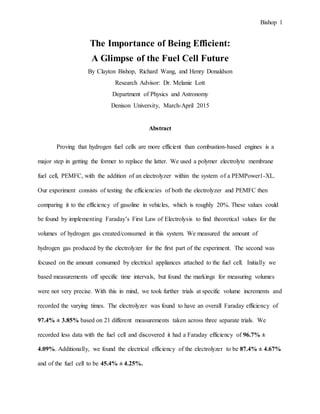
Trial 1:
0
0.2
0.4
0.6
0.8
1
1.2
0 50 100 150 200 250 300 350
Efficiency
Time (seconds)
Electrolyzer Efficiency vs. Time
15. Bishop 15
Trial 2:
Trial 3:
Upon looking at these scatter plots, it becomes clear that the efficiency becomes fairly
constant after 200 seconds in all three trials. There is a clear horizontal asymptote at 1 which
makes sense because the electrolyzer cannot be producing more than it is given. We took time
measurements every time the top of the water level reached the top of each 5 cm3 marking with
the storage tanks.
0
0.2
0.4
0.6
0.8
1
1.2
0 50 100 150 200 250 300 350
Efficiency
Time (seconds)
Electrolyzer Efficiency vs. Time
0
0.2
0.4
0.6
0.8
1
1.2
0 100 200 300 400 500 600
Efficiency
Time (seconds)
Electrolyzer Efficiency vs. Time
16. Bishop 16
This method was more precise than trying to guess where in between tick marks the
water level was at a specific time; which we did during the first attempt of this experiment. There
are only measurement marks at 5 cm3 intervals within the tanks, and so when the water level was
between two of them at say the 2-minute reading, we were left trying to guess the actual water
level. The stop watch is much more precise than the tank measurements, and so we checked that
when we knew we had a decent tank reading.
The fuel cell yielded a final measured Faraday efficiency of 96.7% ± 4.09% and an
electrical efficiency of 45.4% ± 4.25%. Due to the lengthy amount of time this experiment took,
we only got one set of reliable data. Each trial took over an hour, and so we were only able to
attempt one every lab period. Furthermore, after several attempts of getting usable results, we
discovered a leakage in one of the silicon tubes leading out of the fuel cell. Hydrogen gas had
been escaping out this and thus obscuring our numbers. This is exactly what NASA worried
about happening 50 years ago, and so it seems that some technological problems persist
regardless of the era.
Fuel cell efficiency R = 5.6 Ω
t/s V_H2/cm3 Voltage/V I/mA
0 0 - -
900 5 0.754 55.8
1620 10 0.77 59
2220 15 0.73 56.2
2820 20 0.711 55.1
3540 25 0.694 53.5
4140 30 0.68 52.3
Average - 0.723166667 55.31666667
δ - 0.034793199 2.325008961
V_T/cm^3 29.0185841 δV_T/cm^3 1.22942
δt/s 220.4540769 E_H2/J 324
E_electric/J 147.23496 δE_electric/J 13.77372231
η_F 0.967286137 δη_F 0.040980667
17. Bishop 17
η_E 0.454428889 δη_E 0.042511489
The highest electrical efficiency of a PEMFC is considered to be 60%; our findings do
not dispute this as we found out the fuel cell has an electrical efficiency of 45%.
Conclusions
We have found that the Faraday efficiencies of both the electrolyzer and the fuel cell are
very high. The electrolyzer also has a high electrical efficiency. Most importantly, we found that
the electrical efficiency of the fuel cell was greater than that of a combustion engine (45% vs.
20%). We also found that leakages in gas are possible and silent. None of us noticed the leakage
for a while, and it could have produced an explosion had we brought an open flame into the
laboratory. Fuel cells produce both current and heat in a pollutant-free manner. Water is the only
other by-product, and by use of another tube, water sent out of the fuel cell can be returned to the
electrolyzer so that the same amount of water can theoretically help power this system forever.
Throughout the past half century, fuel cells have undergone enough development to go from the
insides of space probes to the phone chargers to possibly replacing the gasoline-powered
combustion engine one day.
i http://www.catf.us/fossil/problems/power_plants/
ii http://www.hydrogen.energy.gov/pdfs/doe_fuelcell_factsheet.pdf
iii http://energy.gov/eere/fuelcells/fuel-cells
iv http://www.sae.org/fuelcells/fuelcells-history.htm
v http://www.americanhistory.si.edu/fuelcells/origins/orig1.htm
vi http://www.fuelcelltoday.com/history
vii http://www.americanhistory.si.edu/fuelcells/pem/pemmain.htm#hist
viii Ibid
ix Ibid
x Ibid
xi Ibid
xii Ibid
xiii http://www.fuelcelltoday.com/history
xiv http://autoweek.com/article/car-reviews/honda-fcx-clarity-dont-be-too-quick-buy-hydrogen-myth
xv http://www.fuelcelltoday.com/history
xvi http://puretecwater.com/what-is-deionized-water.html
xvii Ibid