Optimization of Threshold Voltage for 65nm PMOS Transistor using Silvaco TCAD...
Pape_CfD_Report
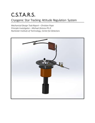
1. C.S.T.A.R.S.
Cryogenic Star Tracking Attitude Regulation System
Mechanical Design Task Report – Christian Pape
Principle Investigator – Michael Zemcov Ph.D
Rochester Institute of Technology, Center for Detectors
2. Table of Contents
Project Description and Goals..............................................................................................................3
Mechanical Design..............................................................................................................................5
LN2/GN2 Plumping System Design...................................................................................................5
Final Design Requirements...........................................................................................................5
Initial Designs..............................................................................................................................5
Adaptations ................................................................................................................................8
Finalized Design ........................................................................................................................10
Future Progress.........................................................................................................................12
CSTARS Cryostat/Dewar Design .....................................................................................................13
Final Design Requirements.........................................................................................................13
Initial Designs............................................................................................................................13
Adaptations ..............................................................................................................................16
Final Design ..............................................................................................................................17
Future Progress.........................................................................................................................20
Telescope/Sensor Interface Design ................................................................................................21
Final Design Requirements.........................................................................................................21
Initial Designs............................................................................................................................21
Adaptations ..............................................................................................................................22
Final Design ..............................................................................................................................25
Future Progress.........................................................................................................................25
Collaboration Efforts.........................................................................................................................26
RIT Center for Detectors CSTARS....................................................................................................26
Team Collaboration...................................................................................................................26
NASA Wallops Flight Center...........................................................................................................27
SPIROL International.....................................................................................................................27
JML Optics....................................................................................................................................27
Universal Cryogenics.....................................................................................................................27
ERG Aerospace .............................................................................................................................27
Works Cited and References..............................................................................................................28
3. Project Description and Goals
The goalof this projectwas to design and fabricatea system thatwas capable
of rocket attitude regulation via star-tracking as the main controller. In this specific
application, a STAR-1000 CMOS detector kept at cryogenic temperatures was
utilized within the cryostat for its star-tracking capabilities. In a long-term goal, this
system is being tested to determine its validity for use in outer solar system
applications for distant stars. Following this, this project will increase the TRL
(Technology Readiness Level) of CMOS applications in space from 4 to 7, taking it
outof the“validationin laboratoryenvironment”anddriving itto “system prototype
demonstration in a space environment.” Belowis a figurefrom NASA describing the
TRL scale from 1-9. [1]
Figure 1: Technology Readiness Level Scale[1]
4. The CMOS sensor, which is a metal oxide semiconductor, operates at
cryogenic levels. The CSTARS cryostathas been designed so that it can be filled with
LN2 (Liquid Nitrogen) in order to cool the sensor and keep it at its operating
temperatureof 73 Kelvin. Thecryogenic aspect of thissensor is advantageousto the
project because the very low temperatures allow for minimal thermal noise, which
ultimately results in clearer pictures and a more precise ability to capturethe light
from the stars with the least interference as possible.
The execution of this method of star-tracking occurs when the CMOS
detector, while in cooperation with the lens array, takes a photograph of distant
stars and calculates their relative distance from a centroid using on-device
algorithms. After a predetermined duration of time, the CMOS detector will again
capture the light from the stars via a photograph and will calculate the relative
centroidonce more.Followingthis, a comparisonbetween thetwo photographswill
be drawn, and using the offset distance of the centroid from the first photo to the
second, the star-tracker will command the attitude regulation system on the rocket
in order to re-orient and get back on the flight path. Below is a figure displaying a
basic change in star pattern that would result in attitude regulation.
This project is a step in a direction not yet taken, and can lead the way for
future star-tracking with CMOS detectors, but also holds key in the future of
autonomous rocket attitude regulation.
Figure 2: Star Cluster Movement [3]
5. Mechanical Design
LN2/GN2 Plumping System Design
Final Design Requirements
The provided design requirementsfor theCSTARS plumbing system called
for a system that was capable of:
Filling the cryostat with LN2
Venting the cryostat of the GN2
Allowing for a manual shut off on fill, and the ability to hold pressure
Utilizing an integrated heat exchanger that can heat the GN2
The ability to emergency vent if 50psia is breached
The ability to hold the dewar at 17psia
Even venting from the system to two symmetrical vents
Utilizing a failsafe to vent the experiment chamber in case of pressure build-up.
Initial Designs
In the two figures below, early schematics for both the LN2 fill and GN2
vent can be seen. Figure 3, detailing the fill line in green, shows the hose
Figure 3: Initial Schematic for LN2 Fill Line [3]
6. connected to the hardlineportion and to the fill port on the cryostat. Within the
hardlineportion of this system, a manual shut-off valve can be seen in line with
the fillportanda tee with a 50psiaemergencyrelief valve. This accomplishedthe
requirementofhaving a manualshut-off valveso thatthefilllineinto the cryostat
can be sealed, but more importantly, a manual purge valve in case immediate
release is necessary. Also, the relief valve meets the requirement of being able
to vent the line in case pressure is peaked during the cryostats operation.
In figure 4, the vent line of the system can be seen in red. This line is
responsibleforthecompletephasechangeofthe LN2 to GN2exiting the cryostat
and for the even and controlled venting of the system. It starts at its connection
point to the cryostat and continues immediately to a tee that has a 50psia
emergency relief valve, which is responsible for venting the line if there is a
blockageor any other reason that would cause a spike of pressurein the system.
Also connected to the tee is the heat exchanger, which will be mounted to the
interior skin of the rocket and will be responsible for the thermal conductivity
from exterior heat into the system. This will heat up the GN2 and ultimately
Figure 4: Initial Schematic for GN2 Vent Line [3]
7. change whatever LN2 is spitting out into GN2, making the temperatures much
morestable and “friendly.” Followthis, thereis a 17psia relief valve thatis in-line
with the system. This valve meets the requirement for the cryostat and the heat
exchanger to be under a 17psia operating pressure, and it will vent as that
pressureis reached, keeping it at the constant pressure level. Once the GN2 has
passed through the 17psia valve, it enters a tee which breaks off into two equal
length hoses that connect to the rocket skin on two opposite, by symmetrical
sides.
Below, in figure 5, a top-down view can be seen in order to get an
understanding for the system layout while in the experiment section. The need
for these hoses to be equal in length to vent perfectly opposing each other is
crucialasan uneven hoseor a non-symmetricalvent layoutwould result in a spin
Figure 5: Top-Down View of the LN2/GN2 Plumbing System [3]
8. due to uneven exhaust on the exterior of the rocket, and this would combatthe
point and effectiveness of the attitude regulation system via CSTARS. Following
this, it is necessary to vent externallyas the cryostatis in an experimentchamber
with other research projects and devices, and unless absolutely necessary, it is
intended to avoid venting inside of the chamber and vent directly to the exterior
of the rocket. In the event of a line blockage or some other issue that causes
either the fill or vent line to breach 50psia, the emergency relief valves will vent,
and this will be vented directly into the chamber. Becauseof the potential of the
chamber becoming pressurized, a 30psia emergency valve will be fixed and
secured to the skin of therocket so that it can vent the chamberoutif necessary.
This will most likely be an uneven vent, but due to the emergencycircumstances
it would be favorable to vent and risk spin on the rocket rather than leave the
chamber pressurized and unstable.
Adaptations
In theinitial design, theschematic called fora heatsink thatwascomprised
of a copper plate, that was milled out, with a soldered copper pipe in place
weaving backand forth through theplate. Below, in figure6, a CAD modelof the
initial design can be seen. Included in this design were soldered-on brass NPT
threaded adapters, for connections to the rest of the system, and a mounting
Figure 6: Initial Heat-Exchanger Design [3]
9. grid of six holes for hardware to attach the heat exchanger. This design was
altered for a few reasons: The size of the copper block was not large enough to
allowforthe necessaryamountof “run” needed with thepipe, asthebendswere
too severe, and using the required bend radius would only allow for three pass-
throughs.Inthe model, five can beseen, butthatis because it depictsbends that
are far too severe to ever be able to be fabricated with a pipe of that diameter.
Following this, the process of filling all of the space between a round pipe and a
square channel with solder would both be unfavorably difficult and expensive,
and it requires more post-processing than what was favored. Lastly, with this
design, it only allows for thermal conductivity with the bottom of the pipe, as
that is the portion attached to the plate. The upper portion of the pipe is not in
contact with any material, ultimately not allowing for the level of thermal
conductivity that was required.
The design was altered so that the amountof “run” called for would work
with the size of the block, and also so that the maximum level of thermal
conductivity could be achieved. Figure 7, below, shows a CAD model of the new
heat exchanger design. It is comprised of two copper plates with mirroring
channels cut into them, with a lay of indium wire in its own respective channel.
Cut holes, with NPTtapped threads,arepresent to allow forinternalmating with
the rest of the plumbing system when the two plates are sandwiched together.
Ascan beseen above,thereis a mountinggridofsix pieces ofextended hardware
for the heat exchanger to be mounted to the inner skin of the rocket. With that,
there is a grid of twelve pieces of hardware, along with washers and nuts, that
Figure 7: Final Heat-Exchanger Design [3]
10. are being used to permanently fix the heat exchanger together, crushing the
indium wire into the channel, and creating a cryogenically-stable seal within the
heat exchanged. This needed to be done to be sure that the GN2, or whatever
little LN2, that is passing through the system does not leak out of the heat
exchanger, and normal O-rings could not be used as they would become brittle
and crack under the circumstances that LN2 passed through the exchanger. In
figure8 below, a CAD model with a transparenttop plate detailing the channels
and the indium wire can be seen.
Finalized Design
The Finalized system called for a few small additions in hardware, such as
a ¼” NPTcoupling and a ¼” NPT pipe extension, so that the new heat exchanger
design could mate properly with the existing design of the plumbing system.
Asidefromthat, all hardwarehasmated correctlyand appropriately,andallhave
undergoneisopropylalcohol baths in order to ensure clean interior surfaces for
Figure 8: Heat-Exchanger Internal Channels [3]
11. testing. Below, in multiple figures, a completed CAD model assembly and real
fabricated components are shown.
Figure 9: Full Finalized Plumbing System CAD Model [3]
Figure 10: Fabricated Fill Line Assembly [3]
12. Future Progress
Atthe currentpointin thefabrication process, theheat exchanger hasnot
been machined. After the heat exchanger is machined and prepped for system
integration, tests will be performed on the plumbing system as a whole. Of the
various test, the three most important will be the leak, pressure, and
temperaturetests. Theleak test will beconducted to makesurethatno LN2/GN2
is leaking from the system, which ensures that during mission execution it is not
leaking into the experiment chamber. The pressure test will encompass letting
the LN2 fill into the cryostat and allowing it to boil off into GN2 and letting the
pressure build until the 17psia relief valve is peaked so that the system vents as
necessary. The next portion will be blocking both the fill and vent lines and
making sure that the 50psia relief valves are functional so that they will vent in
the caseof a malfunctionin the system or an emergency. Lastly, thetemperature
test will make sure that the selected componentswithin the system are capable
of withstanding the extreme 73 K/-200 C/-320 F temperature that is present
during theuse of the system. If the partsfail during thistest, they will need to be
replaced and reconsidered in the overall design of the plumbing system.
Figure 11: Fabricated Vent Line Assemblies [3]
13. CSTARS Cryostat/Dewar Design
Final Design Requirements
The provided design requirements for the CSTARS cryostat called for it to:
Have the ability to maintain a 24 hold time
Have locations for mounting supports/stand-offs on the base
Be equipped with a hermetic connector/feed-through
Have a vacuum valve/port for chamber evacuation
Be designed to interface with a telescope system
Have a 3 liter LN2 holding capacity
Make use of an anti-slosh membrane and G10 supports
Initial Designs
In thefiguresbelow, theoveralldesign can beseen in its initial stages, with
all main components labeled.
Itcan beseen in figure12, thatmost of thedesign requirementswere met
in the initial drafting and modeling of the cryostat. Since most of the critical
design information was not known at the time of initial designing, basic
assumptions were made in terms of dimensions, materials, and layouts. As
Figure 12: Fabricated Vent Line Assemblies [3]
14. progress was made, more defined parameters became known, and the design
was altered in order to meet the specified restrictions.
In its simplest form, this device works by using an on-board dewar, or
container/vessel constructed and rated for holding liquid nitrogen, to keep the
CMOS sensor at its operating temperature, which is at cryogenic levels. The
CMOS sensor is inside of the FPA, or focal plane assembly, which is a PCB with
the sensor mounted on it, all within a light-tight box. This is crucial, becauseonly
the light being emitted from the observed stars should be entering the box, let
alongbeing detected bythe STAR-1000sensor,otherwiseit wouldjeopardizethe
clarityof theimagesand introducenoise. Belowis a figuredepicting earlydesigns
of the focal plane assembly and with the PCB and STAR-1000 exposed.
As it can also be seen in figure 12, there is a radiation shield surrounding
the work surface, or the mountable plate on the dewar where the FPA is being
mounted. This is to protect these sensitive areas and components from the
radiation that exists outside of Earth’s atmosphere. A section view of the
radiation shield around the FPA can be seen below.
Figure 13: Full FPA (Focal Plane Assembly) With Light-Tight Box [3]
15. Inside of the dewar, there is an aluminum foam filling, which is labeled
and purple in figure 12. This foam acts as an anti-sloshing membrane, and also
helpspreventthe rapidboiling-offoftheLN2.Itis importantbecausethepayload
will bein a zero-gravityenvironmentwhich meanstheLN2 will befloatingaround
and have a lot of open surfacearea,which could potentially result in a faster rate
of phase-changing. The aluminum foam helps minimize the amount of open
surfacearea in the LN2,andwill remain atthetemperatureofthe LN2,ultimately
resulting in a longer hold time.
Also included in this design are the G10 supports. These supports have
dualpurposeand effectiveness, and arecrucialto thedesign. They ultimately act
as structuralsupportfor theworksurfacethatis above thedewar, which the FPA
and radiation shield will be mounted to. They are used to guarantee secure and
steady mounting for these assemblies and also provide space for the electrical
wiring and thermometry systems. Aside from this, the G10 material is an
excellent thermalinsulator [2]
and willbevery beneficialin thatsense asthestruts
are secured in an octagonal pattern around the dewar, ultimately holding the
extreme temperatures within the dewar.
Lastly, the design has a built in vacuum valve which has a sealed access to
the inside of the cryostat and dewar. When the rocket reaches its max altitude
Figure 14: Section View of Radiation Shield Surrounding the FPA [3]
16. point and the STAR-1000 begins to take photos, the rocket will have exited the
atmosphere, and with that, it will be in a vacuum. To suit this, our cryostatneeds
to be a vacuum as well, otherwise the pressure inside of it could cause a breach
and/or a catastrophic failureto our system. So, the vacuum valve will allowus to
evacuate the cryostat and dewar before launch so that we can ensure it has as
close to 0 ATM pressure as possible. Partof the mechanicalresponsibility was to
determinewhatkind ofpartsshould be used with the vacuum system and to pick
out he most appropriateorientation for the manual valve. This was completed
and it was found thatthe 90-degreevalve worked best with the design, so it was
implemented.
Adaptations
Adaptationscameat a steady pace, and were worked outwith a company
named Universal Cryogenics. U. Cryo has taken on the responsibility of meeting
the design specifications, and are in the process of fabricating of the cryostat for
it to be shipped to us.
One of the most importantdesign changes was the change of the overall
size of the dewar in the cryostat. The size needed accountfor the ability to hold
3 liters of pure liquid nitrogen, but also the displaced volume of the aluminum
foam and fill pipes that went into the system.
The cavity was redesigned so that the overall volumetric capacity was 3.5
liters, and this allowed for a liquid fillof 3, and a displaced volume of 0.5 litersvia
Figure 15: Initial Interior Fill and Vent Line Design [3]
17. the aluminum foam. After this, the fill and vent pipes inside the dewar received
a design change,as their fullextension to the opposingside of thedewar was not
necessary. Below is a figuredepicting the initialgeometries of thelines inside the
tank.
Due to updated information about the cryostat’s orientations when in
both filland launch position, theuniquegeometries forthe interiorlines were no
longer needed, and could be shortened. This simplification resulted in less
displaced volume within the cryostat, cheaper fabrication costsfor thelines, and
cheaper post-processing requirements for the aluminum foam, as that is taking
up the whole dewar and needs to be cut to fit around the lines.
Final Design
Following the adaptation to the fill lines, the were re-designed and
terminated with stingers just after entering the cryostat. Below is an updated
figure showing their final design inside the tank.
The block-shaped cut out that can be seen around the terminated ends is
displaying the geometryof the cut that will be recessed into the aluminum foam
blocks once they are fabricated and placed inside the dewar.
Figure 16: Interior View of Final Fill and Vent Line [3][4]
18. As the members of the team worked forward, information became
available as to how large the STAR-1000 sensor is, and more importantly, the
required size of the PCB, and also how large the entire FPA would need to be.
This information was gathered and delivered to UniversalCryogenics so that the
finaldesigncould beupdatedandpreppedforfabricationwhennecessary. Below
is the finalized design in a CAD model showing the light-tight box/FPA and the
included STAR-1000 sensor. Also, a thermometry device can be seen.
A few more components went through changes and were brought up to
speed. Theelectrical engineering memberson the projectdetermined what kind
of hermetic connector would be used for the external connection from the
electrical systems, and it was a mechanicalresponsibility to determine the most
appropriate, yet feasible, location for this connector. In the two figures below,
an in-house CAD model of the connector can be seen, as well as its finalized
position on the bottom of the cryostat.
Figure 17: FPA Assembly Mounted to Work Surface [3][4]
19. Figure 18: Connector CAD Model [3][4]
Figure 19: Connector Location on Cryostat [3][4]
20. With these final changes, and some additional minor tweaks to hardware,
the CSTARS cryostatreached its finalized design point. Below is a figureof it in its
final form.
Future Progress
Once the design revisions between CSTARS mechanical and Universal
Cryogenics were completed, the cryostat was pushed into fabrication. Once the
cryostat is received after being constructed, tests and performanceevaluations
will be conducted on it, such as testing its ability to be evacuated, measuring its
totalLN2 holdtime, and performinglaboratorytestsin conjunction with the lenss
arraybeforeits flightmission. Individualtests and evaluations will be performed
on certain componentsas well, mainly being the focal planeassembly and STAR-
1000 sensor.
Figure 20: CSTARS Cryostat Final Design [3][4]
21. Telescope/Sensor Interface Design
Final Design Requirements
The provided design requirements for the telescope and interface system
called for it to:
Have a fixed back-focal distance from the first lens to sensor.
Have the ability to be adjusted via a shimming interface for depth of focus
Attach to a removable mount, via threads
Have a protective window over the sensor, with a retaining ring
Initial Designs
As other aspects of the project, the interface between the telescope and
the sensor was initially designed in a broad state before importantinformation
had been known orgathered.Such information wasthe needed backfocallength
of 25.1mm, and the depth of focus, or +/- 0.13mm distance from the 25.1mm
back focal length.
At this point, the company that was going to fabricate the telescope had
notyet been chosen, so these details had not been available, and the design was
in its initial stages. Below, is a figure depicting the initial mount and interface
design.
Figure 21: Initial Mount Interface [v1] [3]
22. In the initial design, due to not knowing how small both the back-focal
distance and depth of focus would be, the retaining ring was designed to be very
proud (0.75”tall), and theshims werevery thick (~0.1”). Thisdesign satisfied the
needed design requirements though, as it allowed for a large amount of
movement via shims (over 0.5”) and also accounted for a fixed back-focal
distance, it had a threaded mountfor the telescope that could be removed as a
unit, and it had a retaining ring that secured a window into the cryostat cover.
Adaptations
Once information concerning the mechanical properties of the telescope
became known, the design was altered and flushed out to be something more
realistic fora telescope interface.New informationsuggested thatthe back-focal
distancewould beon theorderof ~24mm,andthedepth offocusless than 1mm.
The design was reconsidered and executed for a more feasible interface. Below
is a figure showing this design adaptation.
With this new design, shims could be laid around theretaining ring on the
window, and the mount would sit around thering as well, and slide down until it
was sitting flush in the Z-direction on top of the shims. This resulted in exposed
threads for the mount into the cryostat, but this was considered a design
necessity as the mount needed to move in the positive Z-direction when shims
Figure 22: Redesigned Mount [v2] [3]
23. are added, and it was decided to not machine the shims for hardwareclearance
holes, as it would jeopardize their precision.
With a new mechanical model provided from JML optics, with more
specific lens dimensions and overall mechanical dimensions for interfacing, the
mount was once more redesigned to allot for tighter fits and a more compact
envelope. Below is a figuredepicting thenew mountand the updated telescope.
With this design, the model flushed out well and the telescope interface
mated to the cryostat in a way that was favorable for mission execution, and it
was measured that light would pass through the lens arrayand into the sensor
without any obstructions or known issues. Though, through the process of re-
designing, the retaining ring was made with too large of an inner diameter, and
the beveled cut around theedge now served no purposesince it was completely
out of sight of the lens, and would not be effective and redirecting light rays.
From here, the retaining ring, shims, and the mount for the telescope all
needed to beredesigned, and the interfacemounting for thecryostat needed to
be changed. The mounting grid for the hardwarewas redesigned, as well as the
Figure 23: Updated Mount [v3] [3]
24. seat for the built in windowover the sensor. Below aretwo figuresdepicting this
change in design.
The shim design was altered to account for the new size in the retaining
ring, therefor the shims were increased from 2”/2.5” ID/OD to 2.5”/3” ID/OD.
Figure 24: New Mounting Grid [3]
Figure 25: Redesigned Retaingin Ring [v3] [3]
25. Final Design
The figurebelow depicts a cross-sectionalview of the finalized design of
the cryostat, with all dimensions within the focal planeassembly and the
telescope interfaceup to date and accurate for fabrication. Thedesign has
been solidified and is awaiting fabrication and processing so that it can be
received and tested for interfacing and compatibility.
Future Progress
Once all the fabricated components necessary for construction are
received, the lens array and cryostat will be tested for proper mating and
interfacing. Test will also be performed in a trial-and-error manner in order to
determinehowmany shims, and of whatthicknesses, should be used to properly
focus the lens array in junction with the sensor. Ultimately, after adequate
laboratory tests with the lens and sensor, both in and out of the cryostat, the
CSTARS team will be comfortable enough with the gathered data to be to
assemble the full cryostat system for mission readiness.
Figure 26: CSTARS Interfacing Final Design [3][4]
26. Collaboration Efforts
RIT Center for Detectors CSTARS
The team from left to right:
Project Manager: Hyun Won, Int. Bus.
Team Leader: Kevin Kruse, B.S./M.S. EE
Electrical Engineer: Benjamin Bondor, B.S. EE
Fast Forward Intern: Keegan Evans, B.S. Physics
Software Engineer: Poppy Immel, B.S./M.S. Comp. Math & CS
Mechanical Engineer: Christian Pape, B.S./M.S. MET & MMSI
Instrument Scientist: Matthew Del Favero, B.S. Physics
Mentor/Principle Investigator: Dr. Michael Zemcov
Not Pictured: Dr. Dorin Patru, Chi Nguyen, John Hill, Philip Linden
Team Collaboration
CSTARS is a collaborativeeffortthat requires the skills and contribution of
all thoselisted above, and withoutthe personalexperienceand expertise of each
Figure ##: The Center for Detectors CSTARS Team
27. member, the point of progress made in both research and development would
not have been achieved.
NASA Wallops Flight Center
SPIROL International
JML Optics
Universal Cryogenics
ERG Aerospace
28. Works Cited and References
[1] Dunbar, Brian. "Technology Readiness Level." NASA. NASA, 28 Oct. 2012. Web. 10 Aug. 2016.
[2] Material Measurement Laboratory. "Material Properties: G-10 CR (Fiberglass Epoxy)." CRYOGENIC
TECHNOLOGIESGROUP. National Institute of StandardsandTechnology,n.d.Web.12Aug. 2016.
[3] Propertyof RochesterInstitute of Technology:CenterforDetectors.ModelsandDesignsare original
content.
[4] Propertyof Universal Cryogenics.ModelsandDesignsare original content.