
Recommended
More Related Content
What's hot
What's hot (20)
Similar to Syncrolift: An Overview of Ship Lifting Systems
Similar to Syncrolift: An Overview of Ship Lifting Systems (20)
Recently uploaded
Recently uploaded (20)
Syncrolift: An Overview of Ship Lifting Systems
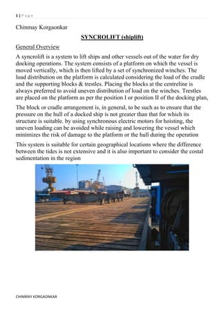
- 1. 1 | P a g e CHINMAY KORGAONKAR Chinmay Korgaonkar SYNCROLIFT (shiplift) General Overview A syncrolift is a system to lift ships and other vessels out of the water for dry docking operations. The system consists of a platform on which the vessel is moved vertically, which is then lifted by a set of synchronized winches. The load distribution on the platform is calculated considering the load of the cradle and the supporting blocks & trestles. Placing the blocks at the centreline is always preferred to avoid uneven distribution of load on the winches. Trestles are placed on the platform as per the position I or position II of the docking plan, The block or cradle arrangement is, in general, to be such as to ensure that the pressure on the hull of a docked ship is not greater than that for which its structure is suitable. by using synchronous electric motors for hoisting, the uneven loading can be avoided while raising and lowering the vessel which minimizes the risk of damage to the platform or the hull during the operation This system is suitable for certain geographical locations where the difference between the tides is not extensive and it is also important to consider the costal sedimentation in the region
- 2. 2 | P a g e CHINMAY KORGAONKAR Working mechanism The platform is movable which can be adjusted as to contour or inclination and it can be raised and lowered in adjusted position which is accomplished by the use of synchronous motors which can be operated independently for adjusting the platform and simultaneously for adjusting the floor, raising and lowering the adjusted platform. The side walls are constructed in any desired manner but mostly a series of piers is preferred and piers are spaced apart at a suitable distance to define a series of alcoves which house the parts of the platform lifting mechanism The platform consists of multiple parallel transversely extending keel supporting beams and multiple intermediate floor sections. The beams are spaced apart a distance equal to the distance between centres of the alcoves and they are supported at their ends by hoisting mechanism. The web beam has a bracket each of which houses the journals of multiple groove pulley. A cable is passed about this pulley and another pulley supported by brackets on channel beams seated on the top of the pier. The cable has one end anchored to a channel and the other end wounded on a drum mounted on the dock and each cable drum is driven by its independent synchronous motor, The motors at any one beam position can be operated independently of the other motors of the system to wind or unwind the cables on the drums to raise or lower the beam. Fig.2 (Lifting platform)
- 3. 3 | P a g e CHINMAY KORGAONKAR Because of this arrangement, the several beams of the floor can be raised to different heights so that the beams will lie along any predetermined keel contour or angle, to the end that each beam of the floor will contact a ship's keel simultaneously when all of the beams are raised together by simultaneous operation of all of the synchronous motors. The web beams are joined together to form a floor by means of the intermediate floor sections. These comprise pairs of transversely spaced, longitudinally extending beams held in spaced relation by bridge members. The floor sections are secured to the beams so as to permit the beams to have relative vertical movement, to prevent swaying of beams. Each of the beams carries a trestle or a pair of bilge blocks upon its upper surface, with the blocks of the pair being on opposite sides of the centre of the beam. The trestles can be moved to desirable position no matter what the elevation of the beam may be. This gives the operator the freedom to present the floor to the plan of the keel and hull of an incoming ship When the ship is floated into the slip the platform may be moved upwardly to make precise contact with the ship along the length of the keel to raise the ship without changing the trim position and without imposing undue stress on any part of the system and the hull Lifting platform also includes upper timber decking components supported on the upper surfaces of beams. Additionally, the platform include rail members for supporting a movable hydraulically operated lifting bogie which is used to transfer the vessel from the ship lift platform to the work bay.
- 4. 4 | P a g e CHINMAY KORGAONKAR To transfer the vessel between the ship lift platform and the berth or reverse, the trestles are lifted up by the hydraulic lifting cylinders of the bogies. The lift cylinders of the bogies are connected to three hydraulic fluid-beds. The vessel will rest on a three-point support with uniform loads for each cylinder within a hydraulic bed. The fluid-bed can also be used during launching or lifting of the vessels. To lift a vessel using fluid bed, the trestles will be positioned on the platform while the bogies remain under the trestles. The bogies are suitable for underwater use. The platform will be lowered and the bogies, in ‘Fluid-Bed’ mode, will go under water. In this case, the trestles rest on the hydraulic cylinders of the bogies. By keeping the hydraulic lifting system in operation during launching or lifting, deformations of the shiplift platform are compensated and the vessels rest on the hydraulic beds with uniform load distributions inside each bed.