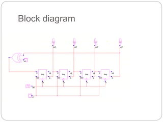
M.A.AZEEM
14204103
LFSR COUNTER
contents
 Introduction
 Block diagram
 Operation
 Applications
 conclusion
Introduction
• LFSR is being studied extensively by engineers, designers and design
for testability.
• LFSR is a shift register whose input bit is a linear function of its
previous state.
• Basically the structure is designed by D-flip flops & EXOR gates.
• LFSR’s are mainly operated in two types:
• Ring counter
• Johnson counter
• The maximum-length of an LFSR sequence is 2n -1
Block diagram
Operation
 LFSR works on the concept of feedback
 Here we use D-registers so as to shift the data by
one unit
 The reset controls that is used for stopping the
ongoing process and set it to ‘0’(initialized)
 The system starts its function when input is high
and reset is made in circuit.
 The EXOR gate will have one input directly and
the other input from the last D-register .
 Thus feedback is given back to the EXOR
gate(input) from the D-register.
Applications
 Counters
 Built-in Self-Test (BIST)
 Military applications
 Encryption
Conclusion
 LFSRs are more popular because of their compact and simple design
 LFSR counter is best implemented using the pass transistors.
THANK Q

LFSR COUNTER.pptx

  • 1.
  • 2.
    contents  Introduction  Blockdiagram  Operation  Applications  conclusion
  • 3.
    Introduction • LFSR isbeing studied extensively by engineers, designers and design for testability. • LFSR is a shift register whose input bit is a linear function of its previous state. • Basically the structure is designed by D-flip flops & EXOR gates. • LFSR’s are mainly operated in two types: • Ring counter • Johnson counter • The maximum-length of an LFSR sequence is 2n -1
  • 4.
  • 5.
    Operation  LFSR workson the concept of feedback  Here we use D-registers so as to shift the data by one unit  The reset controls that is used for stopping the ongoing process and set it to ‘0’(initialized)  The system starts its function when input is high and reset is made in circuit.  The EXOR gate will have one input directly and the other input from the last D-register .  Thus feedback is given back to the EXOR gate(input) from the D-register.
  • 6.
    Applications  Counters  Built-inSelf-Test (BIST)  Military applications  Encryption
  • 7.
    Conclusion  LFSRs aremore popular because of their compact and simple design  LFSR counter is best implemented using the pass transistors.
  • 8.