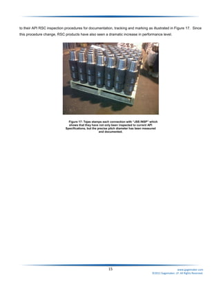
SlideShare a Scribd company logo
1 of 20
Download to read offline
Prevent Rotary Shouldered
Connection Failures
Jim Douglas
Gagemaker, LP
“Prevent Rotary Shouldered Connection Failures” was presented at the American Association of Drilling
Engineer’s 2011 National Technical Conference and Exhibition on April 13, 2011 by Jim Douglas, VP Sales of
Gagemaker, LP.
© 2011 Gagemaker, LP. All rights reserved.
1 www.gagemaker.com
©2011 Gagemaker, LP. All Rights Reserved.
Abstract
Designers of the original rotary shouldered connection (RSC) would never have imagined that their designs
would be taken to the extreme depths and subjected to the severity of directional drilling as they are today.
Companies demand superior RSC performance as they run drilling tools longer and with higher forces to maintain
schedules and reduce time on location. Unfortunately, galled shoulders, swollen boxes and fatigue stress
cracking are costly connection failures that are fairly common and an expected expense by drilling contractors
today.
The root cause of most RSC failures and damage is the lack of thread interference in the connection. The
most important thread element of an RSC connection is the pitch diameter size, which is not addressed in the
current API Specification 7-2 or API RP7G. Consequently, connectors are still manufactured using 92 year old
inspection technology that produces connections that do not have full thread contact or proper radial interference
when torqued together. In order for connections to achieve the performance level required today, a new
approach to gauging and dimensional inspection must be pursued and implemented for not only new, but also
used connections.
This paper explains the importance of isolating the connectors’ pitch diameters from the ring and plug gauge
standoff and the other thread elements, making it a standalone attribute measurement. By measuring the pitch
diameters, the operators can directly control the connector’s size during manufacturing as well as ensure that the
thread cones go into interference properly when the connections are torqued together.
2 www.gagemaker.com
©2011 Gagemaker, LP. All Rights Reserved.
Introduction
Rotary shouldered connectors are key elements of a drill string and are also among the most frequent causes
of failure. The most common RSC failure is fatigue which causes shoulder galling, box swelling and stress
cracks; then these problems lead to drill string failure and possible loss of a bottom hole assembly. Drill string
and bottom hole assembly (BHA) component failures continue to afflict the offshore oil and gas industry annually,
involving direct and consequential costs reaching many millions of dollars.
Due to the increase in well depths and the complexity of drilling operations, the control of drill string
serviceability is becoming more and more significant. Because rotary shouldered connections are one of the
most stressed components of the drill string and they are constantly subjected to both make-up torque and to
axial and bending loads, their design must be systematically scrutinized and inspected. Unfortunately, current
inspection requirements utilizing nearly 100 year old gauging equipment are not as comprehensive as they must
be.
It has been a standard practice to use ring and plug gauges to size both members during the design and
manufacturing production process. Not only are vital measurements not being aptly scrutinized when the
connection is new, but used pipe is never inspected to pinpoint thread element variation which can prevent future
failures; used pipe is only visually inspected for stress cracks and other damage. Therefore, instead of a quick
fifty dollar cleaning or refacing expense, operators face hundreds or thousands of dollars in outsourced machining
and freight charges. This reactive versus a proactive approach must be changed and a new approach to gauging
and dimensional inspection for both new and used pipe must be pursued and implemented.
Costly Unplanned Drilling Events
RSC failures and loss of BHA represent one of the most costly unplanned drilling events that can occur for an
operator. Time spent fishing, wasted rig time and all the additional costs associated with this event significantly
increase the cost of a well and often results in exceeding the approval for expenditure (AFE).
Downtime during drilling is only marginally better than it was a few decades ago. Operator’s estimates
suggest that drilling efficiency is approximately 50% when taking into account all rig activities. A typical AFE,
which includes a detail listing of intangible and tangible drilling costs, show intangible drilling costs can range from
50-75% of the total cost. Then operators typically earmark an additional 10-25% of the total AFE to cover the
unexpected – which equates to millions of dollars.
Cost estimates for downtime on a rig are not straightforward as operators document the expenditures related
to drill string failures differently. So this calculation found is based on fairly conservative round figures. If 50,000
wells are drilled each year worldwide, ranging in day cost from $45,000 on land to $450,000 for semisubmersible
to $1 million on a drillship, the average daily cost could be approximately $250,000 per day. Therefore, based on
an estimate of 6 days of downtime for a well, the average cost is $1.5 million per well.
3 www.gagemaker.com
©2011 Gagemaker, LP. All Rights Reserved.
Why Taper Threads Don’t Fit?
The notion that the root cause of most rotary shouldered connection damage and drill string failure is the lack
of thread cone interference in connections is not new. In January 1949, American Machinist published “Why
Taper Threads Don’t Fit” written by W.E. Burndrett, sales engineer of Pratt & Whitney. In this paper, Burndrett
discussed the difficulty that manufacturers experienced in maintaining their standards and controlling the
interchangeability of the threaded ends. He pinpointed how a slight lead error of a taper threaded product leads
to rapid change in pitch diameter and then small changes in pitch diameter produce large changes in axial travel
which leads to variations in gauge standoff.
Sixty years ago, Burndrett identified that gauge tolerances ultimately affect gauging results and produce
discrepancies. His article advocated for examining each element of the thread with a specific focus on lead,
which is a required measurement today.
In conclusion, Burndrett stated:
“No solution can be offered to relieve this problem, except to stress the necessity for trying to reduce
errors in individual elements, with particular emphasis on lead, and to exert more vigilance over each phase
of manufacture and particularly on gauges in order to reduce the variable to a minimum.”
This acclaimed article has been referenced for over 60 years and various inspection methods evolved from his
analysis. However, the problem of taper threads not fitting still exists and the reason was brought to light by
Burndrett long ago – “…small changes in pitch diameter produce large changes in axial travel.”
Drilling methods have evolved over the years and have become much more severe placing a tremendous
amount of stress on the string and more specifically on the connections. Gauging technology has also evolved
and it’s now possible to measure every element over each phase from manufacturing to the field.
Inspecting the Drill String
The American Petroleum Institute (API) released Recommended Practice RP7G in 1970 to establish an
industry wide standard for accepting or rejecting used drill string components. This release established five
arbitrary classes of drill pipe, numbered 1 (new) to 5 (junk). Classes 2 to 4 represented graduated levels of pipe
displaying signs of wear and tear. Very quickly the industry determined that the best of class (class 2) was not
sufficient for many applications, therefore the premium class was added by 1975. Premium class quickly became
the industry standard for the most part. Since today’s drilling practices are pushing drill strings and particularly
their connections to the limits and beyond, the standards are truly being taken beyond their limits.
The stresses imposed on the drill string during drilling operations can result in rapid accumulation of fatigue
damage and regular inspections are performed to detect mechanical damage and cracking in the rotary
shouldered connectors and in the tubes of drill pipe. Normally, rotary shouldered connections undergo visual,
dimensional and either magnetic particle or penetrant inspections. RP7G does not have any guidelines for thread
inspection nor does it address connection size in reference to fatigue damage and wear.
As an inspector examines any element of a drill string, it’s very important to be cognizant that the acceptable
standards being used are arbitrary and not necessarily adequate.
4 www.gagemaker.com
©2011 Gagemaker, LP. All Rights Reserved.
Specifications for Threading and Gauging of Rotary Shouldered
Connections
The API Spec 7-2 1
st
Edition (released in 2008) is the Specification for Threading and Gauging of Rotary
Shouldered Thread Connections. It specifies requirements on rotary shouldered connections for use in petroleum
and natural gas industries, including dimensional requirements on threads and thread gauges, stipulations on
gauging practice, gauge specifications, as well as instruments and methods for inspection of thread connections.
API Spec 7-2 outlines five basic thread attributes that control the size of the new and recut pin and box
connectors.
For over 92 years, the industry has relied on hardened and ground ring and plug gauges to inspect the pitch
diameter of rotary shouldered connections. It’s the one feature on a connector that has been left to interpretation
by the “fit” of the ring or plug gauge. Basically, the plug gauge is screwed hand tight into the box connector. The
thread is within the permissible tolerance when the gauging face of the working plug is not more than -.000” to
+.010” from being flush with the end of the shoulder (Refer to Figure 1). In gauging pin threads, the ring gauge is
screwed hand tight onto the pin thread. The thread is within the permissible size when the gauging face of the
working ring is -.005” to +0.10” of the nominal
allowable standoff (.625”) (Refer to Figure 2).
If the gauge screws on as specified, the
operator presumes the product is within
tolerance, and when the gauge does not screw
on as specified, the operator presumes the
product will not fit. The standard remedy for a
“non-fitting gauge” is more machining.
Unfortunately, this additional machining only
results in larger box connectors and smaller pin
connectors and doesn’t really fix the problem.
Standoff:
The standoff of the working gauge is intended as a method to locate the
plane of the pitch diameter in relation to the sealing shoulder of the
connection. It is dependent on the other elements of the thread, notably
lead and taper. (Figures 1 and 2)
Lead: The distance a screw thread advances along a taper cone in one revolution.
Taper: The increase in pitch diameter of the thread in inches per foot.
Thread Height: The distance between the crest and root, normal to the axis of the thread.
Thread Form: The form of thread is its profile in an axial plane for a length of one pitch.
Figure 1: Plug Gauge Standoff
5 www.gagemaker.com
©2011 Gagemaker, LP. All Rights Reserved.
Damaging Factors
The most accumulating factor that leads to drill string failure is fatigue,
accounting for more than 40% of all failures. Rotary shouldered
connections typically fail from fatigue in the last engaged thread root of
either the box or pin. Grueling rig operations expose these threads to
greater wear and deformation than fully engaged ones. Since most CNC
threading lathes produce a -0.0005” lead error with thread taper set to
nominal tolerance of .015”/foot, additional clearance is created between
the box and pin threads which ultimately leads to reduced thread
interference.
Reduced thread interference allows movement and increases the stress
between load flanks and results in attrition. Eventually, threads become
worn to a point where there is reduced contact between the pin and box
threads as shown in Figure 3. As this occurs, the last engaged thread(s)
(LET) are the first 2-3 threads near the shoulder of the pin and then the first
2-3 threads near the counter bore of the box, thus the total stress in the connection is distributed over a smaller
area at a location in the box with less cross-sectional area. The combination of these factors reduces the life of
both the pin and box, and consequently results in premature connection failures.
Violent velocities, severe vibrations, whipping, and reverse bending from stick-slip and excessive torques all
contribute to fatigue and stress that lead to most connection
damages. Stick-slip is the rotary acceleration and deceleration
of the drill string which generates continuous torsional
vibrations. The bit can stop rotating momentarily at regular
intervals causing the drill string to windup and the torque to
increase. As the drill tube twists and contracts, the length of
the drill string becomes shorter. Subsequently the stuck drill bit
lifts off the bottom of the hole allowing all the stored energy
from the drill string to produce reverse rotary speeds up to
three times the drilling RPM.
Common Forms of Damage
Thread damage is noted as the most common problem encountered with the use of drill pipe. One of the main
characteristics of thread damage is that it will spread throughout the drill string as one damaged thread connects
with another. Three of the most common forms of damage found in connectors are shoulder galling, box swelling
and stress cracking. Each are the result of a stress concentration encountered at the last thread made up in a
connection. This stressed concentration coupled with wobbling and cycling stress of the connection due to
improper thread make up from lack of interference results in a high incidence of pin and box failures.
Figure 3: Magnified view of stab flank worn due to
fretting, caused by insufficient thread interference.
Figure 2: Ring Gauge Standoff
6 www.gagemaker.com
©2011 Gagemaker, LP. All Rights Reserved.
By design there is an inherent lack of thread interference due to the allowable tolerances for thread taper in pin
and box connectors. This tolerance allows the box to axially pivot against the pin shoulder and the first thread
from the pin nose on the opposite side which produces an oversized oval shaped box opening (Refer to Figure 4
and 5).
At this point, because the box is out of shape and the weaker of the two members, the pin can be screwed
farther into the box causing the box opening to flare like a bell. As this happens, the box and pin shoulders are no
longer parallel to one another and the decrease in surface contact area of the shoulders causes extremely high
contact pressure that deforms both faces.
When a connection starts pivoting or rocking back and forth at the axis created by the clearance between the
thread stab flanks, the 30° angled flanks begin to wear and look like a radius. This damage is induced under load
and in the presence of repeated relative surface motion, better known as “fretting” as shown in Figures 6 and 7.
The fundamental way to prevent fretting is to amend designs which allow no relative motion (axial bending) of the
surfaces that are in contact.
Figure 5: Pin taper with a tolerance in the plus
direction and the lack of thread interference is
circled in red.
Figure 7: Diagram of bell mouthing of the box
connector. Result of undersized pin and
oversized box.
Figure 6: Diagram of a connection bending. Pin thread
fretting, box stress cracks and bell mouthing result.
Figure 4: Box taper with a tolerance in the minus direction and
the lack of thread interference is circled in red.
7 www.gagemaker.com
©2011 Gagemaker, LP. All Rights Reserved.
Design
Designers today draw RSC connectors utilizing various 3D modeling programs; the design is then analyzed
using finite element analysis (FEA) software to evaluate stresses under specific loads. The major flaw with this
process is that the total allowable tolerances for threads (See Table 1) produced during the manufacturing
process are not entered into the equation.
Table 1:
Current API Specification 7-2 Thread Attribute Tolerances of RSC Connectors
Thread Attributes Standoff Gauge to Shoulder Thread Lead Thread Taper Half Angle Thread Form Thread Height
Pin Thread Attributes
-.005"
+/- .0015/in 0/ +.030” 30° or 45°, deg ±0.75°
+.001" -.003
+.010" +.001" -.003
Box Thread Attributes
.000"
+/- .0015/in 0/ -.030” 30° or 45°, deg ±0.75°
+.001" -.003
+.010" +.001" -.003
In other words, analysis is based on models with no lead, pitch diameter, taper, or thread form errors, which
explains why connectors with slight thread errors create potential for failure. Only when models are drawn with
maximum allowable thread attribute tolerances for both connectors will designers see the total effects of reverse
bending and whipping.
Analysis
Several FEA models were constructed and
evaluated for a NC50 tool joint with various
attribute tolerances. Design parameters are
shown in Figure 8.
For the purpose of this study, Young’s
modulus 30e6 psi, Poisons ratio 0.3 and a friction
factor of 0.1 were applied. The following models
illustrate the hot spots or points of highest stress
that the connection experienced. Figure 9
illustrates the interference of the threads on
assembly with 9,167 ft-lbs of torque.
Axial Stress
Axial stress is a tension or compression stress
created in a structural member by the application
of a lengthwise axial load. The following models
illustrate the “hot spots” or “points of highest
Figure 8: FEA Design Parameters
Figure 9: Interference of the threads on assembly using 9,167 ft-lb
torque - resolved but no shoulder contact.
8 www.gagemaker.com
©2011 Gagemaker, LP. All Rights Reserved.
stress” of the connection experienced during makeup.
In Figure 10, 9,167 ft-lbs was resolved for zero pitch
diameter and ±.001 lead with no shoulder loads. In
Figure 11, 30,000 ft-lbs was resolved to allow box
shoulder contact with a contact pressure of 20,000
psi. The LET already shows signs of stress but the
threads are in interference and the connection should
perform as intended.
Finally in Figures 12 & 13, using the pitch diameter
tolerance of ±.012 which is the maximum allowed
pitch diameter tolerance using ring and plug gauges,
the stress experienced by the entire connection is obvious, especially in
the box. By examining the exploded view in Figure 13, the lack of thread
interference is evident as well as the number of critical hot spots.
Essentially, this box and pin would have passed inspection using ring and
plug gauges but this connection may not be able to endure what is
required down hole.
In summary, the connections shown in Figures 12 & 13 are examples
of oversized boxes and undersized pins which would have been approved
using the current API sanctioned ring and plug gauging methods.
However, most importantly, these connections would NOT have been
approved if the pitch diameters were measured with a pitch diameter
gauge using tolerances of ±.002 and ±.004.
Figure 10: Box Pitch Diameter +.000; Pin Pitch Diameter -
.000 /Lead Errors Box +.001 and Pin -.001; 9,167 ft-lb torque;
Figure 11: Box Pitch Diameter +.000; Pin Pitch Diameter -
.000/Lead Errors Box +.001 and Pin -.001; 30,000 ft-lb torque
Figure 12: Box Pitch Diameter +.012; Pin Pitch Diameter -.012
/Lead Errors Box +.001 and Pin -.001; 30,000 ft-lb torque
Figure 13: Closer Look at Figure 12.
9 www.gagemaker.com
©2011 Gagemaker, LP. All Rights Reserved.
Solution
Typically rotary shouldered connection failures and damages are from the lack of thread cone interference
which can be directly related to the pitch diameter size and its acceptable level of tolerance. As shown in figures
9-12, currently allowable pitch diameter tolerances can drastically affect the integrity of a connection. Simply by
measuring and controlling the pitch diameter, the number of threads in interference increase when the
connections are made up. Being able to accurately measure the pitch diameters, independent of the other thread
elements, allows the size of the connection to be regulated during manufacturing and more importantly once the
connector has been used. Without a means of
measuring the pitch diameter independently, each
connector’s pitch diameter can be affected from
.016” - .019” by the cumulative errors in lead, taper
and thread form. These errors lead to oversized box
connectors and undersized pin connectors.
Geometrically a .001” Lead Error generates a
.0034” diameter change as illustrated in Figure 14.
Lead Error / tan30° = Radial change
(.001/tan30°=.0017) x 2 = .0034” on Diameter for
every inch of thread.
Lead error has a particularly drastic effect on pitch diameter. Threads that have allowable lead or other
attribute errors handicap perfectly ground ring and plug gauges and make the gauges standoff prematurely. As a
result, when the gauge standoff is too much, the machinist immediately removes more material which is not
necessarily the right fix. However, by sizing the connector correctly with the addition of a pitch diameter
measurement, the expenses of reworking connectors later can be drastically reduced.
All of the current API specification thread attributes are stand-alone measurements and have their own
tolerance, all except pitch diameter. Pitch diameters historically have been controlled by ring and plug gauges
and were never given a tolerance or gauging method. Ring and plug gauges have been used to size the
connectors functional pitch diameters at a design gauge plane located 5/8” from the pin and box shoulders. The
gauge plane is controlled axially by tolerance. Depending on connector size, the pin diameter sized by a ring
gauge occurs between 1.257” to 1.375” from the pin torque shoulder and in a box connector between 1.125” to
1.500” from the box face. Figure 14 displays the effect lead error or axial movement has on pitch diameter.
Table 2:
Necessary RSC Product Attribute Tolerances
Thread Attribute
Thread Axis
to Shoulder
Standoff
Gauge to
Shoulder
Thread
Lead
Thread
Taper
Half Angle
Thread
Form
Thread
Height
Pitch
Diameter
Tolerance
2” TPF
Pin Thread Attributes .002"
-.005"
+/- .0015/in 0/ +.030”
30° or 45°
±0.75°
+ .001" - .003” - .001”
+.010" + .001" - .003” + .002”
Box Thread Attributes .002"
.000"
+/- .0015/in 0/ -.030”
30° or 45°
±0.75°
+ .001" - .003” .000”
+.010" +.001" - .003” + .002”
Figure 14: Effects of lead error on pitch diameter.
10 www.gagemaker.com
©2011 Gagemaker, LP. All Rights Reserved.
The difference between the API standoff and pitch diameter size on pin and box connections is the result of
lead errors. Lead errors affect ring and plug gauges, but have no effect on pitch diameter gauges. The same
scenario explains why ANSI has calculations for pitch diameter tolerances for UN, Acme and Stub Acme threads
because they recognize that pitch diameter is the only thread attribute that controls the diametrical design size of
the connection without being affected by other thread attributes.
By isolating the connector’s pitch diameter from the ring and plug gauge standoff, pitch diameter gauges
provide a check and balance that ensures that more thread flanks go into interference when the connections are
made up to the designed torques. By design, threads should be in interference prior to or at the same time the
shoulders make contact.
When pitch diameter tolerances are controlled, the connection’s tapered thread cones and shoulders will be in
interference. Torques and bending forces will be distributed more evenly over the entire connection reducing
shoulder galling, box swelling and possibilities of stress cracks. API Spec. 7-2 connection designs can
experience higher levels of performance and longevity with the addition of pitch diameter measurement.
Currently, there is no specification to control pitch diameters on used connections even though boxes are
commonly measured at +.018” to +.028”. Used connectors are easily measured in the field for box swelling and
loss of thread engagement. Better documentation, inspector training and 3rd party verification of thread attribute
tolerances at the manufacturing level will ensure products are being manufactured to API tolerances.
Conclusions
The vibrational and impact loads experienced by rotary shouldered connections result in various forms of
thread damage and failures including shoulder galling, box swelling, thread fretting, stress cracking, and
ultimately, twist offs. It is widely accepted that stress and fatigue of rotary shouldered connections due to
frictional contact between box and pin threads are complex problems. Unfortunately, the complexity of fatigue
and the designer’s unawareness to many of the factors affecting various elements of the connection is another
challenge. Several approaches to alleviate fatigue have been available for years, and many applications have
been tried; however very few have achieved widespread success.
Beginning with its first standards in 1924, API has maintained the API Spec.7-2, Specification for Threading
and Gauging of Rotary Shouldered Thread Connections. For over 87 years, the same tired method of sizing
connections’ pitch diameters has been with ring and plug gauges.
Forward thinking operators and inspectors are now taking advantage of more up to date gauging technology
and performing in-depth inspections of their pipe. Now operators are able to inspect both new and used pipe
threads using precision pitch diameter gauges that allow them to pinpoint early signs of stress, perform
preventative maintenance, and extend the life of their drill string connections.
When the pitch diameter tolerances are more tightly controlled, the connection’s tapered thread cones and
shoulders will be in interference. Therefore drilling torques and bending forces will be more evenly distributed
over the entire connection reducing damage. By adding the pitch diameter measurement to API Spec 7-2 current
connection design, connections can perform more efficiently and last longer.
11 www.gagemaker.com
©2011 Gagemaker, LP. All Rights Reserved.
Amazingly after new connectors have been coated or used, no other means or method of measurement is
currently “required” to verify the reliability of thread elements. Adding precise pitch diameter measurements to
API RP7G will enable operators to detect fatigue, box swelling and loss of thread engagement in the field and on
the rig floor earlier and usually BEFORE stress cracks occur.
Finally, a response is offered to Burndrett’s final conclusion that “No solution can be offered…” Sixty two
years later, a solution to relieve the problem of errors in individual elements with particular emphasis on the lead
as well as the equally important pitch diameter is available. The application of precision gauges measuring lead,
taper, form, height, and pitch diameter can and will minimize error and prevent rotary shouldered connection
failures.
12 www.gagemaker.com
©2011 Gagemaker, LP. All Rights Reserved.
Case Study 1:
StrataLoc Implements New Inspection Procedures
Rick Nichols, BHA Designer with StrataLoc Technology was searching for a way to hold closer tolerance limits
on all the thread attributes of their RSC connections. Because all of StrataLoc’s high tensile straight ACME
threads are currently being measured to ANSI System 22 using Gagemaker’s functional roll and pitch diameter
gauges, Rick decided to inquire about a similar gauge for tapered threads. He then learned of Gagemaker’s Joint
Strength System (JSS) for rotary shouldered connection inspections. He immediately ordered what he needed
and proceeded to measure all his NC70 connections as a trial. He anticipated that measuring the pitch diameters
of the NC70 connections would ensure more interference in the threads prior to shouldering and resist any thread
damage from the stress experienced down hole.
He inspected 15
sets of NC70
connections with the
JSS and the
readings were
recorded as found in
Table 3. The other
connections in the
string, a 6 5/8” API
Reg. box by 7 5/8”
API Reg. pin bit sub,
a 7 5/8” API Reg.
box crossover (drill
bit Sub to BHA) and
the NC56 crossover
were produced at an
outside vendor and measured using only the minimum API required attributes which included ring and plug
gauges.
In December 2009, the BHA tool was run down hole for 8 days in a well south of Oklahoma City to a TD of
12,000’. Then, the rental tool was sent back to Houston, TX. On December 23, 2009, a re-inspection was
performed incorporating the JSS inspection into their normal inspection process. Because the pitch diameter
gauge can also be used on used pipe, these measurements were captured again.
The third party inspection group, Lewis Inspection Company, rejected the 6 5/8 Regular box X 7 5/8 Regular
pin bit sub, 7 5/8 Regular box API cross over (drill bit Sub to BHA) and the NC56 cross over to the drill string for
excessive thread damage per current API RP7G inspection specifications. The damaged parts, shown in Figure
15 & 16, were from the set of connections only inspected to minimum API requirements which included ring and
plug gauges and not JSS.
Box NC70 Date #1 #2 #3 #4 #5 #6 #7 #8 #9 #10 #11 #12 #13 #14 #15
Pitch Diameter -
New
12/1/09 0.0000 -0.0010 0.0000 -0.0005 -0.0005 -0.0010 0.0020 0.0005 0.0000 0.0010 0.0005 0.0000 0.0010 -0.0005 0.0000
Pitch Diameter -
Used
12/23/09 -0.0005 -0.0005 -0.0005 -0.0005 0.0005 0.0005 0.0020 0.0005 0.0040 0.0005 0.0010 0.0005 0.0010 0.0000 0.0005
Lead -0.0005 -0.0005 -0.0005 -0.0005 -0.0005 -0.0005 -0.0005 0.0000 0.0000 -0.0005 -0.0005 -0.0005 0.0000 -0.0005 -0.0005
Damages None None None None None None None Gall 2 Gall 2 None None None None None None
Pin NC70 Date #1 #2 #3 #4 #5 #6 #7
#8
(Stab)
#9
(Stab)
#10 #11 #12 #13 #14 #15
Pitch Diameter -
New
12/1/09 -0.0015 0.0020 -0.0015 -0.0010 -0.0020 0.0070 -0.0015 -0.0010 -0.0015 0.0010 -0.0005 0.0000 0.0010 -0.0005 -0.0005
Pitch Diameter -
Used
12/23/09 -0.0015 -0.0015 -0.0015 -0.0010 -0.0025 -0.0065 -0.0010 -0.0010 -0.0020 0.0005 -0.0010 -0.0005 0.0010 -0.0010 -0.0010
Lead -0.0005 0.0000 -0.0005 -0.0005 -0.0005 0.0000 -0.0005 0.0000 0.0000 -0.0005 -0.0005 -0.0005 0.0000 -0.0005 -0.0005
Damages None None None None None None None None None None None None None None None
Drilpac Collar #1-15 NC70 "Box" End
NC70 Inspection Report Summary
Drilpac Collar #1-15 NC70 "Pin" End
Table 3
13 www.gagemaker.com
©2011 Gagemaker, LP. All Rights Reserved.
They passed the 15 NC70 connections as there was no excessive damage. Only two boxes showed slight
galling on second thread from stabbing damage. This was field dressed and ready to go. These results thrilled
Nichols and StrataLoc Technology now requires all tapered threaded connectors be measured using the JSS
which provides precise measurements for lead, taper, height and most importantly pitch diameter. Since
implementing this new inspection in their procedures, StrataLoc has seen an 85% improvement in performance of
their connections and has had fewer failures in the field.
Figure 15: Damaged threads declared by Lewis
Inspection Group.
Figure 16: 7 5/8 API Regular displayed evidence of thread fretting.
After inspection, it was determined the pin pitch diameter was –.021”.
14 www.gagemaker.com
©2011 Gagemaker, LP. All Rights Reserved.
Case Study 2:
Tejas Tubular Improve Quality and Performance
Eric Otten, Drill Pipe Operations Manager for Tejas Tubular of Houston, TX which is the largest supplier of
aftermarket Horizontal Directional Drilling tubes (HDD), had been searching for ways of controlling tighter pitch
diameter tolerances on their HDD product line to increase connection performances in bending and high torque
applications.
After closely reviewing their internal processes, Otten found that standoff varied greatly and that he needed to
scrutinize the inspection method for each thread attribute. Some of his other discoveries included:
• Lead errors in the CNC machined product threads interfered with their certified ring and plug gauges
ground lead and taper causing premature standoff to the datum torque shoulders.
• The increased amount of gauge standoff was a calculated amount over the length of the connections
every time. Every .0005”/in. lead error resulted in .002” more material being removed from the
connection’s design pitch diameter allowable limits.
• Increased material removal on the pitch diameters reduced all the hoop stresses in the connection, which
were needed to resist over torqueing and bending forces during directional drilling.
After completing his internal investigation, Otten began his search and found the Joint Strength System (JSS)
by Gagemaker which focused on accuracy and precision of rotary shouldered connections. JSS provided a
method to check thread cone taper, thread lead, thread height, thread form, and pitch diameter at the pitch plane
which are all the features that make a connector perform properly. He immediately was intrigued by the
advantages of the JSS pitch diameter gauges for monitoring and holding pitch diameters to tighter tolerances as
well as verifying the repeatability of their CNC lathes on the shop floor. Otten immediately implemented the JSS
on their HDD product line.
Since RSC pitch diameters have never been measured or documented, hundreds of various sizes were
tested. All thread attributes were measured including lead, standoff, pitch diameter, taper and thread form. Table
4 notes a sampling of the values found.
Table 4
Sampling of Box and Pin Measured Values
Lead Standoff from Nominal Pitch Diameter Taper Thread Form
-.001” .000 .006/.012” .1666/.250” √
-.0005” .000 +.003/.006” .1666/.250” √
.000” .000 +.002/.004” .1666/.250” √
+.0005” .000 +.003/.006” .1666/.250” √
+.001” .000 +.006/.012” .1666/.250” √
-.002/.000/+.002” .000 +.018” .1666/.250” √
After great success with HDD products, he then investigated their API RSC connections to see if the same
effects on their ring and plug gauges were affecting the size on their pin and box connectors. And, as expected,
he found the same problems, so he immediately put the JSS into action adding the pitch diameter measurement
15 www.gagemaker.com
©2011 Gagemaker, LP. All Rights Reserved.
to their API RSC inspection procedures for documentation, tracking and marking as illustrated in Figure 17. Since
this procedure change, RSC products have also seen a dramatic increase in performance level.
Figure 17: Tejas stamps each connection with “JSS INSP” which
shows that they have not only been inspected to current API
Specifications, but the precise pitch diameter has been measured
and documented.
16 www.gagemaker.com
©2011 Gagemaker, LP. All Rights Reserved.
Acknowledgements
The author gratefully acknowledges the following people for their help and contributions to
this paper:
Scott Benzie
Mohawk Energy, Houston, TX
Rick Nichols
Strata Loc Technology, Houston, TX
Eric Otten
Tejas Tubular/Premier Drill Pipe, Houston, TX
John Wolfe III
Gagemaker LP, Pasadena, TX
17 www.gagemaker.com
©2011 Gagemaker, LP. All Rights Reserved.
References
1. Burndrett, W.E.: “Why Taper Threads Don’t Fit,” American Machinist, McGraw-Hill Publishing, 1949.
2. Van Der Wissel, H.T.: “Box-and –Pin Type Threaded Joint Having Different Pitches and Pitch
Diameters,” United States Patent # 307,9181, Published Feb. 26, 1963.
3. Farr, A.P., Hughes Tool Co.: “Torque Requirements For Rotary Shouldered Connections And
Selection of Connections For Drill Collars,” paper ASME Petroleum Division, No. 57-PET-19,
presented at the ASME Pertoleum Mechanical Engineering Conference, Tulsa, Oklahoma, 22-25,
September 1957
4. Reed Tubular – Tool Joint United States Patent # 4549754 Published 1985
5. ASM Handbook, the American Society for Metals, Vol.13 "Corrosion", ASM International, 1987.
6. Collins, T. and Vaghi, F.: “Analysis of the Fatigue Resistance of Rotary Shouldered Connections,”
paper 74564-MS presented at IADC/SPE Drilling Conference, Dallas, TX, 26-28 February 2002.
7. Hamid, K. and Shibu, J.: “Drilling String Inspection-The Dilema Between: 1) Oil Operating
Companies, 2) Drilling Contractors and 3) Tubular Inspection Companies,” paper preented at
Middle East Nondestructive Testing Conference & Exhibition, Bahrain, Manama, 27-30 November
2005.
8. Berry, C.: “Drilling Failure Costs Quickly Add Up,” JPT, August 2009.
9. York, P., Pritchard, D, Dodson, J., Dodson, T, Rosenberg, S and Utama, B: “Eliminating Non-
Productive Time Associates with Drilling Trouble Zones,” paper presented at Offshore Technology
Conference, Houston, Texas, 4-7 May 2009.
10. MacDonald, K.A., Deans, W.F.: “Stress Analysis of Drillstring Threaded Connections Using The
Finite Element Method,” Engineering Failure Analysis, Vol. 2, No. 1 pp. 1-30, Aberdeen, U.K. 1995.
11. Kessler, F., Muradov, A., Smith, J.E.: Fatigue “Resistent Disposable Drill Pipe for Short Radius
Applications.”
12. Leine, R.I., Van Campen, D.H., Keultjes, W.J.G.: “Stick-slip Whirl Interaction in Drillstring
Dynamics,” Journal of Vibration and Acoustics, Vol. 124 pp. 209-220, ASME, 2002.
13. Baragetti, S., Baryshnikov, A.: “Rotary Shouldered Thread Connections: Working Limits Under
Combined Static Loading,” Journal of Mechanical Design, Vol 123, Issue 3, 456 (8 pages), Italy,
September 2001.
14. Tollefsen, E., Weber, A., Crowell, D. and Schlumberger, Z.: “Evaluating the True Cost of Losing a
Bottomhole Assembly,” paper 112704 presented at IADC/SPE Drilling Conference, Orlando, FL, 4-6
March 2008.
15. Baryshnikov, A., Anatoly, Ligrone, A., Ferrara, P.: “Optimization of Rotary Shouldered Connection
Reliability and Failure Analysis,” paper 27535-MS presented at SPE/IADC Drilling Conference,
Dallas, TX, 15-18 February, 1994.
16. Kaiser, M.: “A Survey of Drilling Cost and Complexity Estimation Models,” International Journal of
Petroleum Science and Technology, Vol. 1, Number 1, pp. 1-22, 2007.
712 E. Southmore Ave., Pasadena, TX 77502
P.O. Box 87709, Houston, TX 77287-7709
Phone: 713-472-7360
Fax: 713-472-7241
Web site: www.gagemaker.com
E-mail: sales@gagemaker.com
© 2011 Gagemaker, LP. All Rights Reserved.
Quality Thread Gauging Equipment

More Related Content

What's hot

Testing/Manufacture/Automobile, Paint & Plating Testing Equipments
Testing/Manufacture/Automobile, Paint & Plating Testing EquipmentsTesting/Manufacture/Automobile, Paint & Plating Testing Equipments
Testing/Manufacture/Automobile, Paint & Plating Testing Equipmentsfec2020
 
PAUT risk mitigation strategy
PAUT risk mitigation strategyPAUT risk mitigation strategy
PAUT risk mitigation strategyColin Smith
 
Gates Brochure
Gates BrochureGates Brochure
Gates BrochureERIKS UK
 
Plat collection in korea market
Plat collection in korea marketPlat collection in korea market
Plat collection in korea marketChoongil Nam
 
Gates advantage Hydraulic Hose and Couplings
Gates advantage Hydraulic Hose and CouplingsGates advantage Hydraulic Hose and Couplings
Gates advantage Hydraulic Hose and CouplingsLeanne Lennon
 
Eagle Contractors Water Hose - Water Hose Assembly with Bend Restrictor - Wat...
Eagle Contractors Water Hose - Water Hose Assembly with Bend Restrictor - Wat...Eagle Contractors Water Hose - Water Hose Assembly with Bend Restrictor - Wat...
Eagle Contractors Water Hose - Water Hose Assembly with Bend Restrictor - Wat...JGB Enterprises, Inc.
 
Latest cswip 3.1 book
Latest cswip 3.1 bookLatest cswip 3.1 book
Latest cswip 3.1 bookRehan khan
 
Custom Plastic Pipe Extrusions- Product Catalog
Custom Plastic Pipe Extrusions- Product CatalogCustom Plastic Pipe Extrusions- Product Catalog
Custom Plastic Pipe Extrusions- Product CatalogExcalibur Extrusions
 
Twi welding training_6
Twi welding training_6Twi welding training_6
Twi welding training_6Alif Elhasani
 
BGA Cleaning and Inspection
BGA Cleaning and InspectionBGA Cleaning and Inspection
BGA Cleaning and InspectionBob Wettermann
 
criteria of weld defects
criteria of weld defects criteria of weld defects
criteria of weld defects Saqib Rasool
 
Cswip welding inspection notes and questions
Cswip welding inspection notes and questionsCswip welding inspection notes and questions
Cswip welding inspection notes and questionsKarthik Banari
 
As 4822 2008 external field joint coatings for steel pipelines
As 4822 2008 external field joint coatings for steel pipelinesAs 4822 2008 external field joint coatings for steel pipelines
As 4822 2008 external field joint coatings for steel pipelinestoddfly
 
100661266 cswip-3-1-2009
100661266 cswip-3-1-2009100661266 cswip-3-1-2009
100661266 cswip-3-1-2009Jithu John
 

What's hot (19)

cswip-3-1-new-book
 cswip-3-1-new-book cswip-3-1-new-book
cswip-3-1-new-book
 
To whom it may concern
To whom it may concernTo whom it may concern
To whom it may concern
 
Testing/Manufacture/Automobile, Paint & Plating Testing Equipments
Testing/Manufacture/Automobile, Paint & Plating Testing EquipmentsTesting/Manufacture/Automobile, Paint & Plating Testing Equipments
Testing/Manufacture/Automobile, Paint & Plating Testing Equipments
 
PAUT risk mitigation strategy
PAUT risk mitigation strategyPAUT risk mitigation strategy
PAUT risk mitigation strategy
 
Gates Brochure
Gates BrochureGates Brochure
Gates Brochure
 
0 twi introduction
0  twi introduction0  twi introduction
0 twi introduction
 
Welding course design
Welding course designWelding course design
Welding course design
 
Plat collection in korea market
Plat collection in korea marketPlat collection in korea market
Plat collection in korea market
 
Gates advantage Hydraulic Hose and Couplings
Gates advantage Hydraulic Hose and CouplingsGates advantage Hydraulic Hose and Couplings
Gates advantage Hydraulic Hose and Couplings
 
Eagle Contractors Water Hose - Water Hose Assembly with Bend Restrictor - Wat...
Eagle Contractors Water Hose - Water Hose Assembly with Bend Restrictor - Wat...Eagle Contractors Water Hose - Water Hose Assembly with Bend Restrictor - Wat...
Eagle Contractors Water Hose - Water Hose Assembly with Bend Restrictor - Wat...
 
Latest cswip 3.1 book
Latest cswip 3.1 bookLatest cswip 3.1 book
Latest cswip 3.1 book
 
Custom Plastic Pipe Extrusions- Product Catalog
Custom Plastic Pipe Extrusions- Product CatalogCustom Plastic Pipe Extrusions- Product Catalog
Custom Plastic Pipe Extrusions- Product Catalog
 
Twi welding training_6
Twi welding training_6Twi welding training_6
Twi welding training_6
 
BGA Cleaning and Inspection
BGA Cleaning and InspectionBGA Cleaning and Inspection
BGA Cleaning and Inspection
 
criteria of weld defects
criteria of weld defects criteria of weld defects
criteria of weld defects
 
Cswip welding inspection notes and questions
Cswip welding inspection notes and questionsCswip welding inspection notes and questions
Cswip welding inspection notes and questions
 
As 4822 2008 external field joint coatings for steel pipelines
As 4822 2008 external field joint coatings for steel pipelinesAs 4822 2008 external field joint coatings for steel pipelines
As 4822 2008 external field joint coatings for steel pipelines
 
Slide Plates and Rollers in the Fight Against Friction
Slide Plates and Rollers in the Fight Against FrictionSlide Plates and Rollers in the Fight Against Friction
Slide Plates and Rollers in the Fight Against Friction
 
100661266 cswip-3-1-2009
100661266 cswip-3-1-2009100661266 cswip-3-1-2009
100661266 cswip-3-1-2009
 

Viewers also liked

Report on Tubular Non-Destructive Techniques ( Remote Field testing and Inter...
Report on Tubular Non-Destructive Techniques ( Remote Field testing and Inter...Report on Tubular Non-Destructive Techniques ( Remote Field testing and Inter...
Report on Tubular Non-Destructive Techniques ( Remote Field testing and Inter...Akshay Mistri
 
Solution: Long Seam Weld Inspection
Solution: Long Seam Weld InspectionSolution: Long Seam Weld Inspection
Solution: Long Seam Weld InspectionZetec Inc.
 
Technology & it’s impact on our planet
Technology & it’s impact on our planetTechnology & it’s impact on our planet
Technology & it’s impact on our planetDorac87
 
Eddy Current Metal Testing for Conservation
Eddy Current Metal Testing for ConservationEddy Current Metal Testing for Conservation
Eddy Current Metal Testing for ConservationJason Church
 
Automation of Eddy Current Processes for NDT
Automation of Eddy Current Processes for NDTAutomation of Eddy Current Processes for NDT
Automation of Eddy Current Processes for NDTZetec Inc.
 
Tubular Non Destructive techniques (Remote field testing and Internal Rotary ...
Tubular Non Destructive techniques (Remote field testing and Internal Rotary ...Tubular Non Destructive techniques (Remote field testing and Internal Rotary ...
Tubular Non Destructive techniques (Remote field testing and Internal Rotary ...Akshay Mistri
 
Nde examples
Nde examplesNde examples
Nde examplesHarveyGer
 
Jim Reed - The Gas Co. - Pipeline Safety In A Post San Bruno Era
Jim Reed - The Gas Co. - Pipeline Safety In A Post San Bruno EraJim Reed - The Gas Co. - Pipeline Safety In A Post San Bruno Era
Jim Reed - The Gas Co. - Pipeline Safety In A Post San Bruno EraContract Cities
 
Sure NDT Introduction
Sure NDT IntroductionSure NDT Introduction
Sure NDT IntroductionPaul Angus
 
Eddy current testing
Eddy current testingEddy current testing
Eddy current testingzoha nasir
 
Guided Wave Ultrasound - Principles and Apllications
Guided Wave Ultrasound - Principles and ApllicationsGuided Wave Ultrasound - Principles and Apllications
Guided Wave Ultrasound - Principles and Apllicationssubash_j
 
Tutorial - Eddy Current Testing
Tutorial - Eddy Current TestingTutorial - Eddy Current Testing
Tutorial - Eddy Current TestingEthan Gros
 

Viewers also liked (20)

Report on Tubular Non-Destructive Techniques ( Remote Field testing and Inter...
Report on Tubular Non-Destructive Techniques ( Remote Field testing and Inter...Report on Tubular Non-Destructive Techniques ( Remote Field testing and Inter...
Report on Tubular Non-Destructive Techniques ( Remote Field testing and Inter...
 
Solution: Long Seam Weld Inspection
Solution: Long Seam Weld InspectionSolution: Long Seam Weld Inspection
Solution: Long Seam Weld Inspection
 
Aula26 (1)
Aula26 (1)Aula26 (1)
Aula26 (1)
 
Technology & it’s impact on our planet
Technology & it’s impact on our planetTechnology & it’s impact on our planet
Technology & it’s impact on our planet
 
NDT Methods Ready
NDT Methods ReadyNDT Methods Ready
NDT Methods Ready
 
IRIS Scaner
 IRIS Scaner IRIS Scaner
IRIS Scaner
 
Eddy Current Metal Testing for Conservation
Eddy Current Metal Testing for ConservationEddy Current Metal Testing for Conservation
Eddy Current Metal Testing for Conservation
 
TOFD PRO System
TOFD PRO SystemTOFD PRO System
TOFD PRO System
 
Automation of Eddy Current Processes for NDT
Automation of Eddy Current Processes for NDTAutomation of Eddy Current Processes for NDT
Automation of Eddy Current Processes for NDT
 
Tubular Non Destructive techniques (Remote field testing and Internal Rotary ...
Tubular Non Destructive techniques (Remote field testing and Internal Rotary ...Tubular Non Destructive techniques (Remote field testing and Internal Rotary ...
Tubular Non Destructive techniques (Remote field testing and Internal Rotary ...
 
Nde examples
Nde examplesNde examples
Nde examples
 
Jim Reed - The Gas Co. - Pipeline Safety In A Post San Bruno Era
Jim Reed - The Gas Co. - Pipeline Safety In A Post San Bruno EraJim Reed - The Gas Co. - Pipeline Safety In A Post San Bruno Era
Jim Reed - The Gas Co. - Pipeline Safety In A Post San Bruno Era
 
Presentacion general 2016
Presentacion general 2016Presentacion general 2016
Presentacion general 2016
 
Sure NDT Introduction
Sure NDT IntroductionSure NDT Introduction
Sure NDT Introduction
 
Eddy current testing
Eddy current testingEddy current testing
Eddy current testing
 
Guided Wave Ultrasound - Principles and Apllications
Guided Wave Ultrasound - Principles and ApllicationsGuided Wave Ultrasound - Principles and Apllications
Guided Wave Ultrasound - Principles and Apllications
 
Paut full notes
Paut  full notesPaut  full notes
Paut full notes
 
Tutorial - Eddy Current Testing
Tutorial - Eddy Current TestingTutorial - Eddy Current Testing
Tutorial - Eddy Current Testing
 
Testing
TestingTesting
Testing
 
Ndt
NdtNdt
Ndt
 

Similar to Prevent Costly Rotary Connection Failures

Preview drst
Preview drstPreview drst
Preview drstinnobun
 
FINITE ELEMENT ANALYSIS OF BEAM-BEAM BOLTED CONNECTION UNDER PURE MOMENT
FINITE ELEMENT ANALYSIS OF BEAM-BEAM BOLTED CONNECTION UNDER PURE MOMENTFINITE ELEMENT ANALYSIS OF BEAM-BEAM BOLTED CONNECTION UNDER PURE MOMENT
FINITE ELEMENT ANALYSIS OF BEAM-BEAM BOLTED CONNECTION UNDER PURE MOMENTIRJET Journal
 
Esab world pipelines
Esab world pipelinesEsab world pipelines
Esab world pipelinesJorg Eichhorn
 
Orbital Welding Seminar report
Orbital Welding Seminar reportOrbital Welding Seminar report
Orbital Welding Seminar reportAnshad Ali
 
IRJET- Optimization of Process Parameters in MIG Welding of AISI 316L
IRJET- Optimization of Process Parameters in MIG Welding of AISI 316LIRJET- Optimization of Process Parameters in MIG Welding of AISI 316L
IRJET- Optimization of Process Parameters in MIG Welding of AISI 316LIRJET Journal
 
IRJET - Mathematical Modelling to Predict Bead Geometry and Shape Relationshi...
IRJET - Mathematical Modelling to Predict Bead Geometry and Shape Relationshi...IRJET - Mathematical Modelling to Predict Bead Geometry and Shape Relationshi...
IRJET - Mathematical Modelling to Predict Bead Geometry and Shape Relationshi...IRJET Journal
 
Fishbone Article Pumps and Systems
Fishbone Article Pumps and SystemsFishbone Article Pumps and Systems
Fishbone Article Pumps and SystemsDwight Bertozzi
 
IRJET- Finite Element Analysis of Stempipe Used in Deepwater Pipeline Install...
IRJET- Finite Element Analysis of Stempipe Used in Deepwater Pipeline Install...IRJET- Finite Element Analysis of Stempipe Used in Deepwater Pipeline Install...
IRJET- Finite Element Analysis of Stempipe Used in Deepwater Pipeline Install...IRJET Journal
 
DESIGN AND ANALYSIS OF MULTIFACE HYDRAULIC BENDING MACHINE DIE
DESIGN AND ANALYSIS OF MULTIFACE HYDRAULIC BENDING MACHINE DIEDESIGN AND ANALYSIS OF MULTIFACE HYDRAULIC BENDING MACHINE DIE
DESIGN AND ANALYSIS OF MULTIFACE HYDRAULIC BENDING MACHINE DIEIRJET Journal
 
2014 04 (a4) naogp editorial - q&a maats bending machines
2014   04 (a4) naogp editorial - q&a maats bending machines2014   04 (a4) naogp editorial - q&a maats bending machines
2014 04 (a4) naogp editorial - q&a maats bending machinesMaats
 
IRJET- Comparative Study on Rebar Tying Tools with Different Parameters
IRJET- Comparative Study on Rebar Tying Tools with Different ParametersIRJET- Comparative Study on Rebar Tying Tools with Different Parameters
IRJET- Comparative Study on Rebar Tying Tools with Different ParametersIRJET Journal
 
Equipment failure - a liability or an asset? - Roger Costanzi
Equipment failure - a liability or an asset? - Roger CostanziEquipment failure - a liability or an asset? - Roger Costanzi
Equipment failure - a liability or an asset? - Roger CostanziNSW Environment and Planning
 
Design Of Fibrication And Pipe Inspection Robot
Design Of Fibrication And Pipe Inspection RobotDesign Of Fibrication And Pipe Inspection Robot
Design Of Fibrication And Pipe Inspection RobotSuchit Moon
 
Review on Effect of Process Parameters - Friction Stir Welding Process
Review on Effect of Process Parameters - Friction Stir Welding ProcessReview on Effect of Process Parameters - Friction Stir Welding Process
Review on Effect of Process Parameters - Friction Stir Welding ProcessIRJET Journal
 
Vice Cum Bender Machine
Vice Cum Bender MachineVice Cum Bender Machine
Vice Cum Bender MachineIRJET Journal
 
Whitepaper Series Part 1 - Underwater Connectivity
Whitepaper Series Part 1 - Underwater ConnectivityWhitepaper Series Part 1 - Underwater Connectivity
Whitepaper Series Part 1 - Underwater ConnectivityNorthwireCable
 

Similar to Prevent Costly Rotary Connection Failures (20)

Preview drst
Preview drstPreview drst
Preview drst
 
FINITE ELEMENT ANALYSIS OF BEAM-BEAM BOLTED CONNECTION UNDER PURE MOMENT
FINITE ELEMENT ANALYSIS OF BEAM-BEAM BOLTED CONNECTION UNDER PURE MOMENTFINITE ELEMENT ANALYSIS OF BEAM-BEAM BOLTED CONNECTION UNDER PURE MOMENT
FINITE ELEMENT ANALYSIS OF BEAM-BEAM BOLTED CONNECTION UNDER PURE MOMENT
 
SPE 134239
SPE 134239SPE 134239
SPE 134239
 
Esab world pipelines
Esab world pipelinesEsab world pipelines
Esab world pipelines
 
Orbital Welding Seminar report
Orbital Welding Seminar reportOrbital Welding Seminar report
Orbital Welding Seminar report
 
IRJET- Optimization of Process Parameters in MIG Welding of AISI 316L
IRJET- Optimization of Process Parameters in MIG Welding of AISI 316LIRJET- Optimization of Process Parameters in MIG Welding of AISI 316L
IRJET- Optimization of Process Parameters in MIG Welding of AISI 316L
 
Hydraulic catalogue
Hydraulic catalogueHydraulic catalogue
Hydraulic catalogue
 
IRJET - Mathematical Modelling to Predict Bead Geometry and Shape Relationshi...
IRJET - Mathematical Modelling to Predict Bead Geometry and Shape Relationshi...IRJET - Mathematical Modelling to Predict Bead Geometry and Shape Relationshi...
IRJET - Mathematical Modelling to Predict Bead Geometry and Shape Relationshi...
 
Fishbone Article Pumps and Systems
Fishbone Article Pumps and SystemsFishbone Article Pumps and Systems
Fishbone Article Pumps and Systems
 
IRJET- Finite Element Analysis of Stempipe Used in Deepwater Pipeline Install...
IRJET- Finite Element Analysis of Stempipe Used in Deepwater Pipeline Install...IRJET- Finite Element Analysis of Stempipe Used in Deepwater Pipeline Install...
IRJET- Finite Element Analysis of Stempipe Used in Deepwater Pipeline Install...
 
DESIGN AND ANALYSIS OF MULTIFACE HYDRAULIC BENDING MACHINE DIE
DESIGN AND ANALYSIS OF MULTIFACE HYDRAULIC BENDING MACHINE DIEDESIGN AND ANALYSIS OF MULTIFACE HYDRAULIC BENDING MACHINE DIE
DESIGN AND ANALYSIS OF MULTIFACE HYDRAULIC BENDING MACHINE DIE
 
WP Offshore Coating Techniques Aug 2015
WP Offshore Coating Techniques Aug 2015WP Offshore Coating Techniques Aug 2015
WP Offshore Coating Techniques Aug 2015
 
2014 04 (a4) naogp editorial - q&a maats bending machines
2014   04 (a4) naogp editorial - q&a maats bending machines2014   04 (a4) naogp editorial - q&a maats bending machines
2014 04 (a4) naogp editorial - q&a maats bending machines
 
IRJET- Comparative Study on Rebar Tying Tools with Different Parameters
IRJET- Comparative Study on Rebar Tying Tools with Different ParametersIRJET- Comparative Study on Rebar Tying Tools with Different Parameters
IRJET- Comparative Study on Rebar Tying Tools with Different Parameters
 
SPE 147856
SPE 147856SPE 147856
SPE 147856
 
Equipment failure - a liability or an asset? - Roger Costanzi
Equipment failure - a liability or an asset? - Roger CostanziEquipment failure - a liability or an asset? - Roger Costanzi
Equipment failure - a liability or an asset? - Roger Costanzi
 
Design Of Fibrication And Pipe Inspection Robot
Design Of Fibrication And Pipe Inspection RobotDesign Of Fibrication And Pipe Inspection Robot
Design Of Fibrication And Pipe Inspection Robot
 
Review on Effect of Process Parameters - Friction Stir Welding Process
Review on Effect of Process Parameters - Friction Stir Welding ProcessReview on Effect of Process Parameters - Friction Stir Welding Process
Review on Effect of Process Parameters - Friction Stir Welding Process
 
Vice Cum Bender Machine
Vice Cum Bender MachineVice Cum Bender Machine
Vice Cum Bender Machine
 
Whitepaper Series Part 1 - Underwater Connectivity
Whitepaper Series Part 1 - Underwater ConnectivityWhitepaper Series Part 1 - Underwater Connectivity
Whitepaper Series Part 1 - Underwater Connectivity
 

Prevent Costly Rotary Connection Failures

  • 1. Prevent Rotary Shouldered Connection Failures Jim Douglas Gagemaker, LP
  • 2. “Prevent Rotary Shouldered Connection Failures” was presented at the American Association of Drilling Engineer’s 2011 National Technical Conference and Exhibition on April 13, 2011 by Jim Douglas, VP Sales of Gagemaker, LP. © 2011 Gagemaker, LP. All rights reserved.
  • 3. 1 www.gagemaker.com ©2011 Gagemaker, LP. All Rights Reserved. Abstract Designers of the original rotary shouldered connection (RSC) would never have imagined that their designs would be taken to the extreme depths and subjected to the severity of directional drilling as they are today. Companies demand superior RSC performance as they run drilling tools longer and with higher forces to maintain schedules and reduce time on location. Unfortunately, galled shoulders, swollen boxes and fatigue stress cracking are costly connection failures that are fairly common and an expected expense by drilling contractors today. The root cause of most RSC failures and damage is the lack of thread interference in the connection. The most important thread element of an RSC connection is the pitch diameter size, which is not addressed in the current API Specification 7-2 or API RP7G. Consequently, connectors are still manufactured using 92 year old inspection technology that produces connections that do not have full thread contact or proper radial interference when torqued together. In order for connections to achieve the performance level required today, a new approach to gauging and dimensional inspection must be pursued and implemented for not only new, but also used connections. This paper explains the importance of isolating the connectors’ pitch diameters from the ring and plug gauge standoff and the other thread elements, making it a standalone attribute measurement. By measuring the pitch diameters, the operators can directly control the connector’s size during manufacturing as well as ensure that the thread cones go into interference properly when the connections are torqued together.
  • 4. 2 www.gagemaker.com ©2011 Gagemaker, LP. All Rights Reserved. Introduction Rotary shouldered connectors are key elements of a drill string and are also among the most frequent causes of failure. The most common RSC failure is fatigue which causes shoulder galling, box swelling and stress cracks; then these problems lead to drill string failure and possible loss of a bottom hole assembly. Drill string and bottom hole assembly (BHA) component failures continue to afflict the offshore oil and gas industry annually, involving direct and consequential costs reaching many millions of dollars. Due to the increase in well depths and the complexity of drilling operations, the control of drill string serviceability is becoming more and more significant. Because rotary shouldered connections are one of the most stressed components of the drill string and they are constantly subjected to both make-up torque and to axial and bending loads, their design must be systematically scrutinized and inspected. Unfortunately, current inspection requirements utilizing nearly 100 year old gauging equipment are not as comprehensive as they must be. It has been a standard practice to use ring and plug gauges to size both members during the design and manufacturing production process. Not only are vital measurements not being aptly scrutinized when the connection is new, but used pipe is never inspected to pinpoint thread element variation which can prevent future failures; used pipe is only visually inspected for stress cracks and other damage. Therefore, instead of a quick fifty dollar cleaning or refacing expense, operators face hundreds or thousands of dollars in outsourced machining and freight charges. This reactive versus a proactive approach must be changed and a new approach to gauging and dimensional inspection for both new and used pipe must be pursued and implemented. Costly Unplanned Drilling Events RSC failures and loss of BHA represent one of the most costly unplanned drilling events that can occur for an operator. Time spent fishing, wasted rig time and all the additional costs associated with this event significantly increase the cost of a well and often results in exceeding the approval for expenditure (AFE). Downtime during drilling is only marginally better than it was a few decades ago. Operator’s estimates suggest that drilling efficiency is approximately 50% when taking into account all rig activities. A typical AFE, which includes a detail listing of intangible and tangible drilling costs, show intangible drilling costs can range from 50-75% of the total cost. Then operators typically earmark an additional 10-25% of the total AFE to cover the unexpected – which equates to millions of dollars. Cost estimates for downtime on a rig are not straightforward as operators document the expenditures related to drill string failures differently. So this calculation found is based on fairly conservative round figures. If 50,000 wells are drilled each year worldwide, ranging in day cost from $45,000 on land to $450,000 for semisubmersible to $1 million on a drillship, the average daily cost could be approximately $250,000 per day. Therefore, based on an estimate of 6 days of downtime for a well, the average cost is $1.5 million per well.
  • 5. 3 www.gagemaker.com ©2011 Gagemaker, LP. All Rights Reserved. Why Taper Threads Don’t Fit? The notion that the root cause of most rotary shouldered connection damage and drill string failure is the lack of thread cone interference in connections is not new. In January 1949, American Machinist published “Why Taper Threads Don’t Fit” written by W.E. Burndrett, sales engineer of Pratt & Whitney. In this paper, Burndrett discussed the difficulty that manufacturers experienced in maintaining their standards and controlling the interchangeability of the threaded ends. He pinpointed how a slight lead error of a taper threaded product leads to rapid change in pitch diameter and then small changes in pitch diameter produce large changes in axial travel which leads to variations in gauge standoff. Sixty years ago, Burndrett identified that gauge tolerances ultimately affect gauging results and produce discrepancies. His article advocated for examining each element of the thread with a specific focus on lead, which is a required measurement today. In conclusion, Burndrett stated: “No solution can be offered to relieve this problem, except to stress the necessity for trying to reduce errors in individual elements, with particular emphasis on lead, and to exert more vigilance over each phase of manufacture and particularly on gauges in order to reduce the variable to a minimum.” This acclaimed article has been referenced for over 60 years and various inspection methods evolved from his analysis. However, the problem of taper threads not fitting still exists and the reason was brought to light by Burndrett long ago – “…small changes in pitch diameter produce large changes in axial travel.” Drilling methods have evolved over the years and have become much more severe placing a tremendous amount of stress on the string and more specifically on the connections. Gauging technology has also evolved and it’s now possible to measure every element over each phase from manufacturing to the field. Inspecting the Drill String The American Petroleum Institute (API) released Recommended Practice RP7G in 1970 to establish an industry wide standard for accepting or rejecting used drill string components. This release established five arbitrary classes of drill pipe, numbered 1 (new) to 5 (junk). Classes 2 to 4 represented graduated levels of pipe displaying signs of wear and tear. Very quickly the industry determined that the best of class (class 2) was not sufficient for many applications, therefore the premium class was added by 1975. Premium class quickly became the industry standard for the most part. Since today’s drilling practices are pushing drill strings and particularly their connections to the limits and beyond, the standards are truly being taken beyond their limits. The stresses imposed on the drill string during drilling operations can result in rapid accumulation of fatigue damage and regular inspections are performed to detect mechanical damage and cracking in the rotary shouldered connectors and in the tubes of drill pipe. Normally, rotary shouldered connections undergo visual, dimensional and either magnetic particle or penetrant inspections. RP7G does not have any guidelines for thread inspection nor does it address connection size in reference to fatigue damage and wear. As an inspector examines any element of a drill string, it’s very important to be cognizant that the acceptable standards being used are arbitrary and not necessarily adequate.
  • 6. 4 www.gagemaker.com ©2011 Gagemaker, LP. All Rights Reserved. Specifications for Threading and Gauging of Rotary Shouldered Connections The API Spec 7-2 1 st Edition (released in 2008) is the Specification for Threading and Gauging of Rotary Shouldered Thread Connections. It specifies requirements on rotary shouldered connections for use in petroleum and natural gas industries, including dimensional requirements on threads and thread gauges, stipulations on gauging practice, gauge specifications, as well as instruments and methods for inspection of thread connections. API Spec 7-2 outlines five basic thread attributes that control the size of the new and recut pin and box connectors. For over 92 years, the industry has relied on hardened and ground ring and plug gauges to inspect the pitch diameter of rotary shouldered connections. It’s the one feature on a connector that has been left to interpretation by the “fit” of the ring or plug gauge. Basically, the plug gauge is screwed hand tight into the box connector. The thread is within the permissible tolerance when the gauging face of the working plug is not more than -.000” to +.010” from being flush with the end of the shoulder (Refer to Figure 1). In gauging pin threads, the ring gauge is screwed hand tight onto the pin thread. The thread is within the permissible size when the gauging face of the working ring is -.005” to +0.10” of the nominal allowable standoff (.625”) (Refer to Figure 2). If the gauge screws on as specified, the operator presumes the product is within tolerance, and when the gauge does not screw on as specified, the operator presumes the product will not fit. The standard remedy for a “non-fitting gauge” is more machining. Unfortunately, this additional machining only results in larger box connectors and smaller pin connectors and doesn’t really fix the problem. Standoff: The standoff of the working gauge is intended as a method to locate the plane of the pitch diameter in relation to the sealing shoulder of the connection. It is dependent on the other elements of the thread, notably lead and taper. (Figures 1 and 2) Lead: The distance a screw thread advances along a taper cone in one revolution. Taper: The increase in pitch diameter of the thread in inches per foot. Thread Height: The distance between the crest and root, normal to the axis of the thread. Thread Form: The form of thread is its profile in an axial plane for a length of one pitch. Figure 1: Plug Gauge Standoff
  • 7. 5 www.gagemaker.com ©2011 Gagemaker, LP. All Rights Reserved. Damaging Factors The most accumulating factor that leads to drill string failure is fatigue, accounting for more than 40% of all failures. Rotary shouldered connections typically fail from fatigue in the last engaged thread root of either the box or pin. Grueling rig operations expose these threads to greater wear and deformation than fully engaged ones. Since most CNC threading lathes produce a -0.0005” lead error with thread taper set to nominal tolerance of .015”/foot, additional clearance is created between the box and pin threads which ultimately leads to reduced thread interference. Reduced thread interference allows movement and increases the stress between load flanks and results in attrition. Eventually, threads become worn to a point where there is reduced contact between the pin and box threads as shown in Figure 3. As this occurs, the last engaged thread(s) (LET) are the first 2-3 threads near the shoulder of the pin and then the first 2-3 threads near the counter bore of the box, thus the total stress in the connection is distributed over a smaller area at a location in the box with less cross-sectional area. The combination of these factors reduces the life of both the pin and box, and consequently results in premature connection failures. Violent velocities, severe vibrations, whipping, and reverse bending from stick-slip and excessive torques all contribute to fatigue and stress that lead to most connection damages. Stick-slip is the rotary acceleration and deceleration of the drill string which generates continuous torsional vibrations. The bit can stop rotating momentarily at regular intervals causing the drill string to windup and the torque to increase. As the drill tube twists and contracts, the length of the drill string becomes shorter. Subsequently the stuck drill bit lifts off the bottom of the hole allowing all the stored energy from the drill string to produce reverse rotary speeds up to three times the drilling RPM. Common Forms of Damage Thread damage is noted as the most common problem encountered with the use of drill pipe. One of the main characteristics of thread damage is that it will spread throughout the drill string as one damaged thread connects with another. Three of the most common forms of damage found in connectors are shoulder galling, box swelling and stress cracking. Each are the result of a stress concentration encountered at the last thread made up in a connection. This stressed concentration coupled with wobbling and cycling stress of the connection due to improper thread make up from lack of interference results in a high incidence of pin and box failures. Figure 3: Magnified view of stab flank worn due to fretting, caused by insufficient thread interference. Figure 2: Ring Gauge Standoff
  • 8. 6 www.gagemaker.com ©2011 Gagemaker, LP. All Rights Reserved. By design there is an inherent lack of thread interference due to the allowable tolerances for thread taper in pin and box connectors. This tolerance allows the box to axially pivot against the pin shoulder and the first thread from the pin nose on the opposite side which produces an oversized oval shaped box opening (Refer to Figure 4 and 5). At this point, because the box is out of shape and the weaker of the two members, the pin can be screwed farther into the box causing the box opening to flare like a bell. As this happens, the box and pin shoulders are no longer parallel to one another and the decrease in surface contact area of the shoulders causes extremely high contact pressure that deforms both faces. When a connection starts pivoting or rocking back and forth at the axis created by the clearance between the thread stab flanks, the 30° angled flanks begin to wear and look like a radius. This damage is induced under load and in the presence of repeated relative surface motion, better known as “fretting” as shown in Figures 6 and 7. The fundamental way to prevent fretting is to amend designs which allow no relative motion (axial bending) of the surfaces that are in contact. Figure 5: Pin taper with a tolerance in the plus direction and the lack of thread interference is circled in red. Figure 7: Diagram of bell mouthing of the box connector. Result of undersized pin and oversized box. Figure 6: Diagram of a connection bending. Pin thread fretting, box stress cracks and bell mouthing result. Figure 4: Box taper with a tolerance in the minus direction and the lack of thread interference is circled in red.
  • 9. 7 www.gagemaker.com ©2011 Gagemaker, LP. All Rights Reserved. Design Designers today draw RSC connectors utilizing various 3D modeling programs; the design is then analyzed using finite element analysis (FEA) software to evaluate stresses under specific loads. The major flaw with this process is that the total allowable tolerances for threads (See Table 1) produced during the manufacturing process are not entered into the equation. Table 1: Current API Specification 7-2 Thread Attribute Tolerances of RSC Connectors Thread Attributes Standoff Gauge to Shoulder Thread Lead Thread Taper Half Angle Thread Form Thread Height Pin Thread Attributes -.005" +/- .0015/in 0/ +.030” 30° or 45°, deg ±0.75° +.001" -.003 +.010" +.001" -.003 Box Thread Attributes .000" +/- .0015/in 0/ -.030” 30° or 45°, deg ±0.75° +.001" -.003 +.010" +.001" -.003 In other words, analysis is based on models with no lead, pitch diameter, taper, or thread form errors, which explains why connectors with slight thread errors create potential for failure. Only when models are drawn with maximum allowable thread attribute tolerances for both connectors will designers see the total effects of reverse bending and whipping. Analysis Several FEA models were constructed and evaluated for a NC50 tool joint with various attribute tolerances. Design parameters are shown in Figure 8. For the purpose of this study, Young’s modulus 30e6 psi, Poisons ratio 0.3 and a friction factor of 0.1 were applied. The following models illustrate the hot spots or points of highest stress that the connection experienced. Figure 9 illustrates the interference of the threads on assembly with 9,167 ft-lbs of torque. Axial Stress Axial stress is a tension or compression stress created in a structural member by the application of a lengthwise axial load. The following models illustrate the “hot spots” or “points of highest Figure 8: FEA Design Parameters Figure 9: Interference of the threads on assembly using 9,167 ft-lb torque - resolved but no shoulder contact.
  • 10. 8 www.gagemaker.com ©2011 Gagemaker, LP. All Rights Reserved. stress” of the connection experienced during makeup. In Figure 10, 9,167 ft-lbs was resolved for zero pitch diameter and ±.001 lead with no shoulder loads. In Figure 11, 30,000 ft-lbs was resolved to allow box shoulder contact with a contact pressure of 20,000 psi. The LET already shows signs of stress but the threads are in interference and the connection should perform as intended. Finally in Figures 12 & 13, using the pitch diameter tolerance of ±.012 which is the maximum allowed pitch diameter tolerance using ring and plug gauges, the stress experienced by the entire connection is obvious, especially in the box. By examining the exploded view in Figure 13, the lack of thread interference is evident as well as the number of critical hot spots. Essentially, this box and pin would have passed inspection using ring and plug gauges but this connection may not be able to endure what is required down hole. In summary, the connections shown in Figures 12 & 13 are examples of oversized boxes and undersized pins which would have been approved using the current API sanctioned ring and plug gauging methods. However, most importantly, these connections would NOT have been approved if the pitch diameters were measured with a pitch diameter gauge using tolerances of ±.002 and ±.004. Figure 10: Box Pitch Diameter +.000; Pin Pitch Diameter - .000 /Lead Errors Box +.001 and Pin -.001; 9,167 ft-lb torque; Figure 11: Box Pitch Diameter +.000; Pin Pitch Diameter - .000/Lead Errors Box +.001 and Pin -.001; 30,000 ft-lb torque Figure 12: Box Pitch Diameter +.012; Pin Pitch Diameter -.012 /Lead Errors Box +.001 and Pin -.001; 30,000 ft-lb torque Figure 13: Closer Look at Figure 12.
  • 11. 9 www.gagemaker.com ©2011 Gagemaker, LP. All Rights Reserved. Solution Typically rotary shouldered connection failures and damages are from the lack of thread cone interference which can be directly related to the pitch diameter size and its acceptable level of tolerance. As shown in figures 9-12, currently allowable pitch diameter tolerances can drastically affect the integrity of a connection. Simply by measuring and controlling the pitch diameter, the number of threads in interference increase when the connections are made up. Being able to accurately measure the pitch diameters, independent of the other thread elements, allows the size of the connection to be regulated during manufacturing and more importantly once the connector has been used. Without a means of measuring the pitch diameter independently, each connector’s pitch diameter can be affected from .016” - .019” by the cumulative errors in lead, taper and thread form. These errors lead to oversized box connectors and undersized pin connectors. Geometrically a .001” Lead Error generates a .0034” diameter change as illustrated in Figure 14. Lead Error / tan30° = Radial change (.001/tan30°=.0017) x 2 = .0034” on Diameter for every inch of thread. Lead error has a particularly drastic effect on pitch diameter. Threads that have allowable lead or other attribute errors handicap perfectly ground ring and plug gauges and make the gauges standoff prematurely. As a result, when the gauge standoff is too much, the machinist immediately removes more material which is not necessarily the right fix. However, by sizing the connector correctly with the addition of a pitch diameter measurement, the expenses of reworking connectors later can be drastically reduced. All of the current API specification thread attributes are stand-alone measurements and have their own tolerance, all except pitch diameter. Pitch diameters historically have been controlled by ring and plug gauges and were never given a tolerance or gauging method. Ring and plug gauges have been used to size the connectors functional pitch diameters at a design gauge plane located 5/8” from the pin and box shoulders. The gauge plane is controlled axially by tolerance. Depending on connector size, the pin diameter sized by a ring gauge occurs between 1.257” to 1.375” from the pin torque shoulder and in a box connector between 1.125” to 1.500” from the box face. Figure 14 displays the effect lead error or axial movement has on pitch diameter. Table 2: Necessary RSC Product Attribute Tolerances Thread Attribute Thread Axis to Shoulder Standoff Gauge to Shoulder Thread Lead Thread Taper Half Angle Thread Form Thread Height Pitch Diameter Tolerance 2” TPF Pin Thread Attributes .002" -.005" +/- .0015/in 0/ +.030” 30° or 45° ±0.75° + .001" - .003” - .001” +.010" + .001" - .003” + .002” Box Thread Attributes .002" .000" +/- .0015/in 0/ -.030” 30° or 45° ±0.75° + .001" - .003” .000” +.010" +.001" - .003” + .002” Figure 14: Effects of lead error on pitch diameter.
  • 12. 10 www.gagemaker.com ©2011 Gagemaker, LP. All Rights Reserved. The difference between the API standoff and pitch diameter size on pin and box connections is the result of lead errors. Lead errors affect ring and plug gauges, but have no effect on pitch diameter gauges. The same scenario explains why ANSI has calculations for pitch diameter tolerances for UN, Acme and Stub Acme threads because they recognize that pitch diameter is the only thread attribute that controls the diametrical design size of the connection without being affected by other thread attributes. By isolating the connector’s pitch diameter from the ring and plug gauge standoff, pitch diameter gauges provide a check and balance that ensures that more thread flanks go into interference when the connections are made up to the designed torques. By design, threads should be in interference prior to or at the same time the shoulders make contact. When pitch diameter tolerances are controlled, the connection’s tapered thread cones and shoulders will be in interference. Torques and bending forces will be distributed more evenly over the entire connection reducing shoulder galling, box swelling and possibilities of stress cracks. API Spec. 7-2 connection designs can experience higher levels of performance and longevity with the addition of pitch diameter measurement. Currently, there is no specification to control pitch diameters on used connections even though boxes are commonly measured at +.018” to +.028”. Used connectors are easily measured in the field for box swelling and loss of thread engagement. Better documentation, inspector training and 3rd party verification of thread attribute tolerances at the manufacturing level will ensure products are being manufactured to API tolerances. Conclusions The vibrational and impact loads experienced by rotary shouldered connections result in various forms of thread damage and failures including shoulder galling, box swelling, thread fretting, stress cracking, and ultimately, twist offs. It is widely accepted that stress and fatigue of rotary shouldered connections due to frictional contact between box and pin threads are complex problems. Unfortunately, the complexity of fatigue and the designer’s unawareness to many of the factors affecting various elements of the connection is another challenge. Several approaches to alleviate fatigue have been available for years, and many applications have been tried; however very few have achieved widespread success. Beginning with its first standards in 1924, API has maintained the API Spec.7-2, Specification for Threading and Gauging of Rotary Shouldered Thread Connections. For over 87 years, the same tired method of sizing connections’ pitch diameters has been with ring and plug gauges. Forward thinking operators and inspectors are now taking advantage of more up to date gauging technology and performing in-depth inspections of their pipe. Now operators are able to inspect both new and used pipe threads using precision pitch diameter gauges that allow them to pinpoint early signs of stress, perform preventative maintenance, and extend the life of their drill string connections. When the pitch diameter tolerances are more tightly controlled, the connection’s tapered thread cones and shoulders will be in interference. Therefore drilling torques and bending forces will be more evenly distributed over the entire connection reducing damage. By adding the pitch diameter measurement to API Spec 7-2 current connection design, connections can perform more efficiently and last longer.
  • 13. 11 www.gagemaker.com ©2011 Gagemaker, LP. All Rights Reserved. Amazingly after new connectors have been coated or used, no other means or method of measurement is currently “required” to verify the reliability of thread elements. Adding precise pitch diameter measurements to API RP7G will enable operators to detect fatigue, box swelling and loss of thread engagement in the field and on the rig floor earlier and usually BEFORE stress cracks occur. Finally, a response is offered to Burndrett’s final conclusion that “No solution can be offered…” Sixty two years later, a solution to relieve the problem of errors in individual elements with particular emphasis on the lead as well as the equally important pitch diameter is available. The application of precision gauges measuring lead, taper, form, height, and pitch diameter can and will minimize error and prevent rotary shouldered connection failures.
  • 14. 12 www.gagemaker.com ©2011 Gagemaker, LP. All Rights Reserved. Case Study 1: StrataLoc Implements New Inspection Procedures Rick Nichols, BHA Designer with StrataLoc Technology was searching for a way to hold closer tolerance limits on all the thread attributes of their RSC connections. Because all of StrataLoc’s high tensile straight ACME threads are currently being measured to ANSI System 22 using Gagemaker’s functional roll and pitch diameter gauges, Rick decided to inquire about a similar gauge for tapered threads. He then learned of Gagemaker’s Joint Strength System (JSS) for rotary shouldered connection inspections. He immediately ordered what he needed and proceeded to measure all his NC70 connections as a trial. He anticipated that measuring the pitch diameters of the NC70 connections would ensure more interference in the threads prior to shouldering and resist any thread damage from the stress experienced down hole. He inspected 15 sets of NC70 connections with the JSS and the readings were recorded as found in Table 3. The other connections in the string, a 6 5/8” API Reg. box by 7 5/8” API Reg. pin bit sub, a 7 5/8” API Reg. box crossover (drill bit Sub to BHA) and the NC56 crossover were produced at an outside vendor and measured using only the minimum API required attributes which included ring and plug gauges. In December 2009, the BHA tool was run down hole for 8 days in a well south of Oklahoma City to a TD of 12,000’. Then, the rental tool was sent back to Houston, TX. On December 23, 2009, a re-inspection was performed incorporating the JSS inspection into their normal inspection process. Because the pitch diameter gauge can also be used on used pipe, these measurements were captured again. The third party inspection group, Lewis Inspection Company, rejected the 6 5/8 Regular box X 7 5/8 Regular pin bit sub, 7 5/8 Regular box API cross over (drill bit Sub to BHA) and the NC56 cross over to the drill string for excessive thread damage per current API RP7G inspection specifications. The damaged parts, shown in Figure 15 & 16, were from the set of connections only inspected to minimum API requirements which included ring and plug gauges and not JSS. Box NC70 Date #1 #2 #3 #4 #5 #6 #7 #8 #9 #10 #11 #12 #13 #14 #15 Pitch Diameter - New 12/1/09 0.0000 -0.0010 0.0000 -0.0005 -0.0005 -0.0010 0.0020 0.0005 0.0000 0.0010 0.0005 0.0000 0.0010 -0.0005 0.0000 Pitch Diameter - Used 12/23/09 -0.0005 -0.0005 -0.0005 -0.0005 0.0005 0.0005 0.0020 0.0005 0.0040 0.0005 0.0010 0.0005 0.0010 0.0000 0.0005 Lead -0.0005 -0.0005 -0.0005 -0.0005 -0.0005 -0.0005 -0.0005 0.0000 0.0000 -0.0005 -0.0005 -0.0005 0.0000 -0.0005 -0.0005 Damages None None None None None None None Gall 2 Gall 2 None None None None None None Pin NC70 Date #1 #2 #3 #4 #5 #6 #7 #8 (Stab) #9 (Stab) #10 #11 #12 #13 #14 #15 Pitch Diameter - New 12/1/09 -0.0015 0.0020 -0.0015 -0.0010 -0.0020 0.0070 -0.0015 -0.0010 -0.0015 0.0010 -0.0005 0.0000 0.0010 -0.0005 -0.0005 Pitch Diameter - Used 12/23/09 -0.0015 -0.0015 -0.0015 -0.0010 -0.0025 -0.0065 -0.0010 -0.0010 -0.0020 0.0005 -0.0010 -0.0005 0.0010 -0.0010 -0.0010 Lead -0.0005 0.0000 -0.0005 -0.0005 -0.0005 0.0000 -0.0005 0.0000 0.0000 -0.0005 -0.0005 -0.0005 0.0000 -0.0005 -0.0005 Damages None None None None None None None None None None None None None None None Drilpac Collar #1-15 NC70 "Box" End NC70 Inspection Report Summary Drilpac Collar #1-15 NC70 "Pin" End Table 3
  • 15. 13 www.gagemaker.com ©2011 Gagemaker, LP. All Rights Reserved. They passed the 15 NC70 connections as there was no excessive damage. Only two boxes showed slight galling on second thread from stabbing damage. This was field dressed and ready to go. These results thrilled Nichols and StrataLoc Technology now requires all tapered threaded connectors be measured using the JSS which provides precise measurements for lead, taper, height and most importantly pitch diameter. Since implementing this new inspection in their procedures, StrataLoc has seen an 85% improvement in performance of their connections and has had fewer failures in the field. Figure 15: Damaged threads declared by Lewis Inspection Group. Figure 16: 7 5/8 API Regular displayed evidence of thread fretting. After inspection, it was determined the pin pitch diameter was –.021”.
  • 16. 14 www.gagemaker.com ©2011 Gagemaker, LP. All Rights Reserved. Case Study 2: Tejas Tubular Improve Quality and Performance Eric Otten, Drill Pipe Operations Manager for Tejas Tubular of Houston, TX which is the largest supplier of aftermarket Horizontal Directional Drilling tubes (HDD), had been searching for ways of controlling tighter pitch diameter tolerances on their HDD product line to increase connection performances in bending and high torque applications. After closely reviewing their internal processes, Otten found that standoff varied greatly and that he needed to scrutinize the inspection method for each thread attribute. Some of his other discoveries included: • Lead errors in the CNC machined product threads interfered with their certified ring and plug gauges ground lead and taper causing premature standoff to the datum torque shoulders. • The increased amount of gauge standoff was a calculated amount over the length of the connections every time. Every .0005”/in. lead error resulted in .002” more material being removed from the connection’s design pitch diameter allowable limits. • Increased material removal on the pitch diameters reduced all the hoop stresses in the connection, which were needed to resist over torqueing and bending forces during directional drilling. After completing his internal investigation, Otten began his search and found the Joint Strength System (JSS) by Gagemaker which focused on accuracy and precision of rotary shouldered connections. JSS provided a method to check thread cone taper, thread lead, thread height, thread form, and pitch diameter at the pitch plane which are all the features that make a connector perform properly. He immediately was intrigued by the advantages of the JSS pitch diameter gauges for monitoring and holding pitch diameters to tighter tolerances as well as verifying the repeatability of their CNC lathes on the shop floor. Otten immediately implemented the JSS on their HDD product line. Since RSC pitch diameters have never been measured or documented, hundreds of various sizes were tested. All thread attributes were measured including lead, standoff, pitch diameter, taper and thread form. Table 4 notes a sampling of the values found. Table 4 Sampling of Box and Pin Measured Values Lead Standoff from Nominal Pitch Diameter Taper Thread Form -.001” .000 .006/.012” .1666/.250” √ -.0005” .000 +.003/.006” .1666/.250” √ .000” .000 +.002/.004” .1666/.250” √ +.0005” .000 +.003/.006” .1666/.250” √ +.001” .000 +.006/.012” .1666/.250” √ -.002/.000/+.002” .000 +.018” .1666/.250” √ After great success with HDD products, he then investigated their API RSC connections to see if the same effects on their ring and plug gauges were affecting the size on their pin and box connectors. And, as expected, he found the same problems, so he immediately put the JSS into action adding the pitch diameter measurement
  • 17. 15 www.gagemaker.com ©2011 Gagemaker, LP. All Rights Reserved. to their API RSC inspection procedures for documentation, tracking and marking as illustrated in Figure 17. Since this procedure change, RSC products have also seen a dramatic increase in performance level. Figure 17: Tejas stamps each connection with “JSS INSP” which shows that they have not only been inspected to current API Specifications, but the precise pitch diameter has been measured and documented.
  • 18. 16 www.gagemaker.com ©2011 Gagemaker, LP. All Rights Reserved. Acknowledgements The author gratefully acknowledges the following people for their help and contributions to this paper: Scott Benzie Mohawk Energy, Houston, TX Rick Nichols Strata Loc Technology, Houston, TX Eric Otten Tejas Tubular/Premier Drill Pipe, Houston, TX John Wolfe III Gagemaker LP, Pasadena, TX
  • 19. 17 www.gagemaker.com ©2011 Gagemaker, LP. All Rights Reserved. References 1. Burndrett, W.E.: “Why Taper Threads Don’t Fit,” American Machinist, McGraw-Hill Publishing, 1949. 2. Van Der Wissel, H.T.: “Box-and –Pin Type Threaded Joint Having Different Pitches and Pitch Diameters,” United States Patent # 307,9181, Published Feb. 26, 1963. 3. Farr, A.P., Hughes Tool Co.: “Torque Requirements For Rotary Shouldered Connections And Selection of Connections For Drill Collars,” paper ASME Petroleum Division, No. 57-PET-19, presented at the ASME Pertoleum Mechanical Engineering Conference, Tulsa, Oklahoma, 22-25, September 1957 4. Reed Tubular – Tool Joint United States Patent # 4549754 Published 1985 5. ASM Handbook, the American Society for Metals, Vol.13 "Corrosion", ASM International, 1987. 6. Collins, T. and Vaghi, F.: “Analysis of the Fatigue Resistance of Rotary Shouldered Connections,” paper 74564-MS presented at IADC/SPE Drilling Conference, Dallas, TX, 26-28 February 2002. 7. Hamid, K. and Shibu, J.: “Drilling String Inspection-The Dilema Between: 1) Oil Operating Companies, 2) Drilling Contractors and 3) Tubular Inspection Companies,” paper preented at Middle East Nondestructive Testing Conference & Exhibition, Bahrain, Manama, 27-30 November 2005. 8. Berry, C.: “Drilling Failure Costs Quickly Add Up,” JPT, August 2009. 9. York, P., Pritchard, D, Dodson, J., Dodson, T, Rosenberg, S and Utama, B: “Eliminating Non- Productive Time Associates with Drilling Trouble Zones,” paper presented at Offshore Technology Conference, Houston, Texas, 4-7 May 2009. 10. MacDonald, K.A., Deans, W.F.: “Stress Analysis of Drillstring Threaded Connections Using The Finite Element Method,” Engineering Failure Analysis, Vol. 2, No. 1 pp. 1-30, Aberdeen, U.K. 1995. 11. Kessler, F., Muradov, A., Smith, J.E.: Fatigue “Resistent Disposable Drill Pipe for Short Radius Applications.” 12. Leine, R.I., Van Campen, D.H., Keultjes, W.J.G.: “Stick-slip Whirl Interaction in Drillstring Dynamics,” Journal of Vibration and Acoustics, Vol. 124 pp. 209-220, ASME, 2002. 13. Baragetti, S., Baryshnikov, A.: “Rotary Shouldered Thread Connections: Working Limits Under Combined Static Loading,” Journal of Mechanical Design, Vol 123, Issue 3, 456 (8 pages), Italy, September 2001. 14. Tollefsen, E., Weber, A., Crowell, D. and Schlumberger, Z.: “Evaluating the True Cost of Losing a Bottomhole Assembly,” paper 112704 presented at IADC/SPE Drilling Conference, Orlando, FL, 4-6 March 2008. 15. Baryshnikov, A., Anatoly, Ligrone, A., Ferrara, P.: “Optimization of Rotary Shouldered Connection Reliability and Failure Analysis,” paper 27535-MS presented at SPE/IADC Drilling Conference, Dallas, TX, 15-18 February, 1994. 16. Kaiser, M.: “A Survey of Drilling Cost and Complexity Estimation Models,” International Journal of Petroleum Science and Technology, Vol. 1, Number 1, pp. 1-22, 2007.
  • 20. 712 E. Southmore Ave., Pasadena, TX 77502 P.O. Box 87709, Houston, TX 77287-7709 Phone: 713-472-7360 Fax: 713-472-7241 Web site: www.gagemaker.com E-mail: sales@gagemaker.com © 2011 Gagemaker, LP. All Rights Reserved. Quality Thread Gauging Equipment