
Recommended
Recommended
More Related Content
What's hot
What's hot (20)
Similar to 5G and Future Antenna Technology -- C&T RF Antennas Inc
Similar to 5G and Future Antenna Technology -- C&T RF Antennas Inc (20)
More from Antenna Manufacturer Coco
More from Antenna Manufacturer Coco (20)
Recently uploaded
Recently uploaded (20)
5G and Future Antenna Technology -- C&T RF Antennas Inc
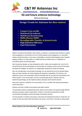
- 1. C&T RF Antennas Inc www.ctrfantennas.com rfproducts1@ctrfantennas.com Please Contact us for more information, thank you. Jasmine Lu (86)17322110281 5G and future antenna technology Written by Calio Huang Abstract: According to the definition of the industry, an antenna is a transducer that transforms a guided wave propagating on a transmission line into an electromagnetic wave propagating in an unbounded medium (usually free space), or vice versa, ie transmitting or receiving. Electromagnetic waves. Popularly speaking, whether it is a base station or a mobile terminal, the antenna acts as a middleware for transmitting signals and receiving signals. Over the past two decades, we have witnessed the shift in mobile communications from 1G to 4G LTE. During this period, the key technologies of communication are changing, and the amount of information processed has multiplied. The antenna is an indispensable component to achieve this leapfrog. Now, the next-generation communication technology, 5G, has entered the end of the standard-setting stage, and major operators are actively deploying 5G equipment. Undoubtedly, 5G will bring a new experience to users, it has a transmission rate ten times faster than 4G, and puts new requirements on the antenna system. In 5G communication, the key to achieving high speed is millimeter wave and beamforming technology, but the traditional antenna obviously cannot meet this demand. What kind of antenna is needed for 5G communication? This is a problem that engineering developers need to think about. Evolution and trend of mobile communication base station antenna The base station antenna is developed along with network communication, and engineers design different antennas according to network requirements. Therefore, in the past few generations of mobile communication technologies, antenna technology has also been evolving. The first generation of mobile communication used almost all omnidirectional antennas. At that time, the number of users was small and the transmission rate was low. At this time, it was also an analog system.
- 2. C&T RF Antennas Inc www.ctrfantennas.com rfproducts1@ctrfantennas.com Please Contact us for more information, thank you. Jasmine Lu (86)17322110281 By the second generation of mobile communication technology, we entered the cellular era. The antenna at this stage has gradually evolved into a directional antenna, and the general lobe width includes 60° and 90° and 120°. Taking 120° as an example, it has three sectors. The antennas of the 1980s were mainly dominated by single-polarized antennas, and the concept of arrays has begun to be introduced. Although omnidirectional antennas also have arrays, they are only vertical arrays, and single-polarized antennas have planar and directional antennas. In terms of form, the current antenna is very similar to the second generation antenna. In 1997, dual-polarized antennas (± 45° cross-multi-polarized antennas) began to enter the historical arena. At this time, the performance of the antenna has been greatly improved compared with the previous generation. Whether it is 3G or 4G, the main trend is a dual-polarized antenna. In the 2.5G and 3G era, many multi-band antennas appeared. Because the system at this time is very complicated, such as GSM, CDMA, etc. need to coexist, the multi-band antenna is an inevitable trend. In order to reduce costs and space, multi-band has become the mainstream at this stage. By 2013, we introduced the MIMO (Multiple-Input Multiple-Output) antenna system for the first time. Originally a 4x4 MIMO antenna. MIMO technology has increased communication capacity, and the antenna system has entered a new era, from the original single antenna to the array antenna and multiple antennas. However, now we need to look into the distance, the deployment of 5G has started, what role will antenna technology play in 5G, and what effect will 5G have on antenna design? This is a problem we need to explore. In the past, the design of the antenna was usually very passive: after the system design was completed, the indicator was added to customize the antenna. However, the current concept of 5G is still unclear. R&D personnel who do antenna design need to be prepared in advance to provide solutions for 5G communication systems, and even influence the customization and development of 5G standards through new antenna solutions or technologies. From the experience of cooperation and exchange between mobile communication companies in the past few years, there are two major trends in base station antennas in the future. The first is from passive antennas to active antenna systems. This means that the antenna may be intelligent, miniaturized (co-designed), and customized. As the future of the network will become more and more detailed, we need to customize the design according to the surrounding scenes, for example, the station in the urban area will be more elaborate, rather than simple coverage. 5G communication will use high-frequency bands, obstacles will have a great impact on communication, and customized antennas can provide better network quality. The second trend is the systematic and complex antenna design. For example, beam arrays (implementing space division multiplexing), multiple beams, and multiple/high-frequency bands. These all put high demands on the antenna, it will involve the whole system and the problem of mutual compatibility. In this case, the antenna technology has surpassed the concept of components and gradually entered the design of the system.
- 3. C&T RF Antennas Inc www.ctrfantennas.com rfproducts1@ctrfantennas.com Please Contact us for more information, thank you. Jasmine Lu (86)17322110281 The evolution of antenna technology: from the single array of antennas to multiple arrays to multiple units, from passive to active systems, from simple MIMO to massive MIMO systems, from simply fixed beams to multiple beams. Design level trend For base stations, a major principle of antenna design is miniaturization. Antennas of different systems are designed together and are small enough to reduce cost and save space. Therefore, the antenna is required to be multi-band, wide-band, multi-beam, MIMO/Massive MIMO, and MIMO to antenna isolation. Massive MIMO has some special requirements for the hybrid coupling of antennas. In addition, the antenna also needs to be tunable. The first generation of antennas was mechanically used to achieve tilt angles, and the third generation achieved remote ESCs. 5G is very attractive if it can be self-tuned. For mobile terminals, the requirements for the antenna are also miniaturized, multi-band, wide frequency band, and tunable. Although these features are now available, the 5G requirements will be more demanding. In addition, the antenna of 5G mobile communication faces a new problem - coexistence. To achieve Massive MIMO, multiple antennas are required for transmission and reception, that is, multi-antenna (8-antenna, 16-antenna...). The biggest challenge for such a multi-antenna system to the terminal is coexistence. How to reduce the mutual influence on the couple, how to increase the isolation of the channel... This puts new requirements on the 5G terminal antenna. Specifically, it will cover the following three points: Reducing the mutual influence, especially the different functional modules, the mutual interference between different frequency bands, which was not considered by the academic community before, but it does exist in the industry; Decoupling, in MIMO systems, the mutual coupling of the antenna not only reduces the isolation of the channel but also reduces the radiation efficiency of the entire system. In addition, we can't expect to rely entirely on high-band millimeter-waves to address performance gains, such as 25GHz, 28GHz...60GHz. De-correlation, which can be solved by the antenna and circuit design coordination, but the bandwidth of the solution is very limited by the circuit, and it is difficult to meet the bandwidth of all frequency bands. Antenna technology for 5G systems This includes the design of a single antenna and the technology at the system level, as mentioned above at the system level, such as multi-beam, beamforming, an active antenna array, Massive MIMO, etc. From the perspective of specific antenna design, the technology developed by the metamaterial-based concept will be of great benefit. Metamaterials have been successful in 3G and 4G, such as miniaturization, low profile, high gain, and band. The second is the substrate or package integrated antenna. These antennas are mainly used in the frequency band with high frequency, that is, the millimeter wave band. Although the antenna size in the
- 4. C&T RF Antennas Inc www.ctrfantennas.com rfproducts1@ctrfantennas.com Please Contact us for more information, thank you. Jasmine Lu (86)17322110281 high-frequency band is small, the loss of the antenna itself is very large, so it is preferable to integrate the antenna and the substrate integration or a smaller package on the terminal. The third is an electromagnetic lens. The lens is mainly used in high-frequency bands. When the wavelength is very small, a medium can be placed to focus. The high-frequency antenna is not large, but the wavelength of the microwave segment is very long, which makes the lens difficult to use. It will be great. The fourth is the application of MEMS. At very low frequencies, MEMS can be used as a switch. In mobile terminals, if the antenna can be effectively controlled and reconstructed, an antenna can be used. Taking an electromagnetic lens as an example, this design introduces a concept: an electromagnetic lens is placed in front of a multi-unit antenna array (here, a lens applied to the low-end frequency band of microwave or millimeter wave, unlike a conventional optical lens), when light When incident from an angle, spots are generated on a focal plane, which concentrates a large amount of power, which means that the main part of the entire capability is received in a small area. When the incident direction changes, the position of the spot on the focal plane also changes. As shown above, when the angle is being projected, the energy distribution of the black color is generated. If it is incident at an angle θ (red color), the main energy deviates from the black color region. This concept can be used to distinguish where the energy comes from, and the direction of incidence and the position of the energy on the array or on the focal plane are one-to-one. Conversely, if the antenna is excited at different positions, the antenna will radiate in different directions, which is also one-to-one correspondence. If a plurality of cells is radiated on the focal plane, radiation of a plurality of carrier beams can be generated, that is, so-called beamforming; if switching between the beams, beam scanning occurs; if these antennas are used simultaneously, Massive MIMO can be implemented. This array can be large, but high gain radiation can be achieved with very few arrays per beam. If a normal array has the same size, each time the energy is received, all the units must receive energy in this area. If only one unit is placed in a large area, the energy received is only a very small part; The difference in an array is that the same caliber can receive all the energy with only a few units without any loss. Different angles come in, and this energy can be received simultaneously in different places. This greatly simplifies the entire system. If there is only one direction per work, only one local antenna can work, which reduces the number of simultaneous working antennas. The concept of subarray is different. It is to make the local multi-antenna form a sub-array. At this time, the number of channels decreases as the number of sub-array units increases. For example, a 10× 10 array, if it becomes a sub-array with 5× 5, then it becomes only four independent channels, and the total number of channels is reduced. The right side of the figure above shows the effect of the lens on the system calculated on the baseband. The horizontal direction is the number of antennas. It is assumed that there are 20 units in a horizontal array in the horizontal direction. In the case of a lens, only 5 units are accepted. The energy after focusing is better than the use of all 20 units of the lens. The former has higher communication quality and lower cost and power consumption. Even in the worst case, the wave is incident from all directions, and the 20 units are the same as the latter. Therefore, the use of lenses can improve the performance of the antenna - with a small number of antennas, to achieve the effect of large arrays in the past.
- 5. C&T RF Antennas Inc www.ctrfantennas.com rfproducts1@ctrfantennas.com Please Contact us for more information, thank you. Jasmine Lu (86)17322110281 It can be seen from this PPT that the use of an electromagnetic lens can reduce cost, reduce complexity, increase radiation efficiency, and increase the filtering characteristics of the antenna array (masking interference signals) and the like. When the incident direction changes, the position of the spot on the focal plane also changes. As shown above, when the angle is being projected, the energy distribution of the black color is generated. If it is incident at an angle θ (red color), the main energy deviates from the black color region. This concept can be used to distinguish where the energy comes from, and the direction of incidence and the position of the energy on the array or on the focal plane are one-to-one. Conversely, if the antenna is excited at different positions, the antenna will radiate in different directions, which is also one-to-one correspondence. If a plurality of cells is radiated on the focal plane, radiation of a plurality of carrier beams can be generated, that is, so-called beamforming; if switching between the beams, beam scanning occurs; if these antennas are used simultaneously, Massive MIMO can be implemented. This array can be large, but high gain radiation can be achieved with very few arrays per beam. If a normal array has the same size, each time the energy is received, all the units must receive energy in this area. If only one unit is placed in a large area, the energy received is only a very small part; The difference in an array is that the same caliber can receive all the energy with only a few units without any loss. Different angles come in, and these energies can be received simultaneously in different places. This greatly simplifies the entire system. If there is only one direction per work, only one local antenna can work, which reduces the number of simultaneous working antennas. The concept of subarray is different. It is to make the local multi-antenna form a sub-array. At this time, the number of channels decreases as the number of sub-array units increases. For example, a 10× 10 array, if it becomes a sub-array with 5× 5, then it becomes only four independent channels, and the total number of channels is reduced. The right side of the figure above shows the effect of the lens on the system calculated on the baseband. The horizontal direction is the number of antennas. It is assumed that there are 20 units in a horizontal array in the horizontal direction. In the case of a lens, only 5 units are accepted. The energy after focusing is better than the use of all 20 units of the lens. The former has higher communication quality and lower cost and power consumption. Even in the worst case, the wave is incident from all directions, and the 20 units are the same as the latter. Therefore, the use of lenses can improve the performance of the antenna - with a small number of antennas, to achieve the effect of large arrays in the past. It can be seen from this PPT that the use of an electromagnetic lens can reduce cost, reduce complexity, increase radiation efficiency, and increase the filtering characteristics of the antenna array (masking interference signals) and the like. Millimeter wave antenna design As we all know, 5G will have two bands of low-frequency band and millimeter wave, and the wavelength of a millimeter wave is very short and the loss is very large, so in 5G communication, we must solve this problem. The first solution is a substrate integrated antenna (SIA).
- 6. C&T RF Antennas Inc www.ctrfantennas.com rfproducts1@ctrfantennas.com Please Contact us for more information, thank you. Jasmine Lu (86)17322110281 This kind of antenna is mainly based on two technologies: the loss caused by the medium when the air waveguide is transmitted is small, so the air waveguide can be used for the feed transmission. However, there are several problems. Because it is an air waveguide, it is very large in size and cannot be integrated with other circuits, so it is suitable for high-power, large-volume applications. The other is microstrip technology, which can be mass-produced, but It is inherently a loss of transmission medium and it is difficult to form a large-scale antenna array. Based on these two technologies, a substrate integrated waveguide technology can be produced. This technique was first proposed by the Japanese industry. They published the first waveguide structure paper on dielectric integration in 1998. They mentioned that the waveguide is realized on a very thin dielectric substrate, and the electromagnetic waves are blocked by small columns to avoid Expanded on both sides. It is not difficult to understand that when the distance between two small pillars is the one-quarter wavelength of the fish, the energy will not leak out, which can form high efficiency, high gain, low profile, low cost, easy integration, low loss. Antenna. At the bottom right of the figure above is a 60 GHz antenna made on the LTCC using this technique, with a gain of 25 dB and a size of 8 x 8 cells. This scheme is suitable for the application of millimeter waves on the base station, and there is another scheme on the mobile terminal. The second solution is to design the antenna in a package integrated antenna (PIA). Because the biggest problem with the antenna on the chip is that the loss is too large, and the size of the chip itself is small, the design of the antenna will increase the cost, so it is almost impossible to obtain a large-scale application in engineering. If the antenna is designed with a package (larger than the chip) as a carrier, not only can a single antenna be designed, but also an antenna array can be designed, which avoids the limitation in size, loss, and cost of the antenna directly on the silicon. In fact, the antenna can be designed not only inside the package but also at the top, bottom and around the package. Another point to be aware of is whether the PCB can be used as an antenna. The answer is yes. The key bottleneck is not the material itself, but the design and processing problems that the material brings. However, the PCB is only suitable for the frequency band below 60 GHz, and LTCC is recommended after 60 GHz, but after 200 GHz, the LTCC also has a bottleneck. To sum up In the future, the antenna must be designed together with the system instead of being designed separately. It can even be said that the antenna will become a bottleneck of 5G. If the bottleneck is not broken, the signal processing on the system cannot be realized, so the antenna has become a 5G mobile communication system. Key technology. An antenna is not just a radiator. It has filtering characteristics, amplification, and suppression of interference signals. It does not require energy to achieve gain, so the antenna is more than just a device.