
Recommended
More Related Content
What's hot
What's hot (20)
Similar to 3D MIMO large-scale array antenna in 5G - C&T RF Antennas Inc
Similar to 3D MIMO large-scale array antenna in 5G - C&T RF Antennas Inc (20)
More from Antenna Manufacturer Coco
More from Antenna Manufacturer Coco (20)
Recently uploaded
Recently uploaded (20)
3D MIMO large-scale array antenna in 5G - C&T RF Antennas Inc
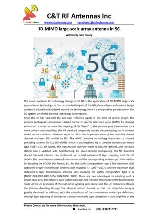
- 1. C&T RF Antennas Inc www.ctrfantennas.com rfproducts1@ctrfantennas.com Please Contact us for more information, thank you. Jasmine Lu (86)17322110281 3D-MIMO large-scale array antenna in 5G Written By Calio Huang The most important RF technology change in 5G NR is the application of 3D-MIMO large-scale array antenna technology so that a considerable part of the NR physical layer architecture design content is adapted and updated around the technology. Here is a comparative perspective on the 5G system. 3D-MIMO antenna technology is introduced. Since the 5G has canceled the cell-level reference signal at the time of system design, the antenna port signal transmission is based on the UE-specific reference signal (DMRS) for channel estimation. In order to make the mapping of the "layer" to the antenna port transmission data more uniform and simplified, the NR standard completely cancels the pre-coding matrix scheme based on the cell-level reference signal in LTE in the implementation of the downlink shared channel and uses 3D- similar to LTE. The MIMO antenna technology implements a shaped precoding scheme for SU/MU-MIMO, which is accompanied by a complex transmission mode type TM1-TM10. Of course, the transmission diversity mode is also not defined, and the base station side is updated with beamforming. For space-division multiplexing, the NR downlink shared transport channel can implement up to dual codeword-8 layer mapping, and the UE obtains the transmission codeword information and the corresponding antenna port information by decoding the PDCCH DCI format 1-1, for the DMRS configuration type 1 The maximum dual codeword-8 layer transmission antenna port mapping is {1000~1007}, and the maximum dual codeword-8 layer transmission antenna port mapping for DMRS configuration type 2 is {1000,1001,1002,1003,1006,1007,1008, 1009}. There are two advantages to adopting such a design idea. First, the network base station side does not transmit the change of the transmission mode of the UE by means of the high-level signaling semi-static, and the UE completely obtains the dynamic decoding through the physical control channel, so that the interaction delay is greatly shortened. In addition, with the cancellation of the transmission mode type definition, the high layer signaling of the bearer transmission mode type conversion is also simplified at the
- 2. C&T RF Antennas Inc www.ctrfantennas.com rfproducts1@ctrfantennas.com Please Contact us for more information, thank you. Jasmine Lu (86)17322110281 same time, reducing the signaling load overhead of the network and the terminal side. Just as LTE's concept of introducing CSI-RS after R10 is consistent, the CSI-RS setting in NR is also a very important parameter to determine the multi-stream transmission effect of large-scale array antenna SU/MU-MIMO. In the current protocol version, the maximum number of configurable CSI-RS antenna ports for LTE and NR is 32, which is closely related to the channel shaping weight capability of 3D-MIMO antenna devices. There are three ways to configure the CSI-RS reference signal in the NR. It can be configured as a periodic transmission type or semi-statically configured as a non-periodic or semi-persistent transmission type through high-level signaling. Although the CSI-RS reference signal itself is given a richer connotation in the NR, for example, the UE can perform time-frequency domain position-precision locking and beam-switching-based mobility measurement through CSI-RS, but combined with 3D-MIMO antenna technology, based on the measurement of the PDSCH reference resource corresponding to the CSI-RS performs channel quality reporting (CQI) and closed-loop precoding codebook index (PMI) for the base station to perform the shaping precoding matrix selection, which is still the most typical application value thereof. . In addition, the related CSI report information includes the CRI (CSI-RS resource indicator) report, LI (layer indicator) report, and SSBRI (SSB resource indicator) report. Since the CSI-RS can perform multiple resource configurations, the UE clears the measurement resources related to the CSI reporting through the CRI. The LI characterizes a column of the precoding matrix corresponding to the PMI, and the column happens to be the strongest layer mapping corresponding to the codeword with the best transmission channel condition. If the connected state UE needs to report the physical layer channel RSRP measurement, the CSI report may be configured to be based on cri-RSRP or SSB-Index-RSRP. If the latter is required, the SSB port explicitly combined with the SSBRI needs to be used. UE has more flexibility. In the connected state, it can evaluate the channel coverage by measuring the CSI-RS, or it can be evaluated by the SSB beam. The information is fed back to the base station, and the base station can comprehensively optimize and adjust according to a specific algorithm. The design of 5G NR based on codebook feedback in PMI is much more complicated than LTE. It is divided into two types: Type I and Type II. Each type contains two types of subtypes. The main difference between the two types is that the codebook accuracy is different, and the accompanying PMI feedback overhead is also different. Type I is divided into single antenna array board codebook and multi-antenna array board codebook. Multi-antenna array board codebook usage scenario is similar to LTE transmission mode. Multi-cell joint ComP technology in TM10 can realize multi-AAU joint transmission, multi-antenna array board code. In this case, it is assumed that the phase of the transmitted signal between the panels is constant. The current protocol is defined at 8, 16 and 32 CSI-RS ports, and the number of multi-antenna array boards can be 2 or 4. Type II further improves the accuracy of the feedback codebook based on Type I. Of course, the feedback overhead is also large. Currently, the protocol specifies that the rank (RI) of the channel does not exceed 2 based on the PMI feedback type. Type II measures CSI-RS narrow beam reporting through terminal selection and combines the amplitude and phase feedback information to assist the base station to approximate the ideal shaping weight performance. It is worth noting that the Type I codebook subset limitation defined by the higher layer parameter specifies the specific Whether the codebook subset is optional, and the Type II codebook subset
- 3. C&T RF Antennas Inc www.ctrfantennas.com rfproducts1@ctrfantennas.com Please Contact us for more information, thank you. Jasmine Lu (86)17322110281 restriction specifies the upper limit of the associated amplitude value of the specific codebook. The Type II subtype 2 reports the port weight codebook based on the polarization direction, and the base station can further improve the spatial beamforming accuracy by combining the specific CSI-RS precoding matrix. The 5G NR uplink shared channel can be selected based on both the codebook and the non-codebook. Both of the transmission modes are performed by the UE decodes the PDCCH DCI format 0_0, the DCI format 0_1, or the semi-static configuration mode. The base station determines whether the UE uses the codebook transmission mode by using the high-level parameter txConfig configuration. If the parameter is not configured, the uplink shared channel transmission mode adopts a single-antenna port mode. At this time, the UE does not expect the transmission resource to be scheduled by the PDCCH DCI format 0_1 but may be Scheduled by DCI format 0_0. In order to make better use of the base station multi-antenna array based on the SRS (Sounding Reference Signal) reporting channel correlation to achieve multi-beam shaping, the 5G terminal can support SRS based on different antenna port rotation or concurrency, SRI (SRS resource indicator) It is an identifier of the SRS resource configuration, which can be used to clarify the round or concurrent SRS signal. The essential difference between the uplink shared channel codebook transmission and the non-codebook transmission is whether the base station side sends a codebook indication (TPMI) to assist the terminal in performing precoding matrix selection. For these two transmission modes, the selectable precoding matrix set is the same. In the codebook transmission mode, the LTE terminal needs to perform codebook transmission selection according to the TPMI (Transmitted Precoding Matrix Indicator) and the number of channel ranks, and the 5G terminal can be dynamically scheduled based on DCI or higher layer. The SRI, TPMI, and transport channel rank RI delivered by the semi-persistent scheduling of parameters independently determine the precoding codebook, which gives the terminal certain flexibility. The base station needs to refer to the SRS signal when selecting the codebook and needs to associate with the corresponding SRI when delivering the TPMI. In the non-codebook transmission mode, according to the channel reciprocity principle, the terminal can select an uplink precoding matrix by measuring a downlink channel of an NZP-CSI-RS resource configured in advance with the SRS, and it is worth mentioning that, in order to According to the reciprocity evaluation, only one SRS resource set can be configured in the non-codebook transmission mode, and one SRS resource can be configured in one resource set. Only one SRS port can be configured for each SRS resource, and the SRS can also be precoded. This design is mainly designed to adapt to the continuous upgrade of 5G terminals in the future and can also achieve narrow beamforming. The non-codebook transmission mode saves the codebook indication information overhead compared to the codebook transmission mode. In addition to the narrow beamforming technology of 3D-MIMO in the downlink shared traffic channel, the 5G NR differs from the earlier versions of LTE in that the downlink control channel and the physical signal can also be narrow beamformed by a specific algorithm. The information decoding success rate of the control channel can be improved, and on the other hand, by combining with the traffic channel precoding matrix, the space division multiplexing effect of the traffic channel can be further improved. Although the control channel shaping technology is not
- 4. C&T RF Antennas Inc www.ctrfantennas.com rfproducts1@ctrfantennas.com Please Contact us for more information, thank you. Jasmine Lu (86)17322110281 explicitly reflected in the 3GPP protocol, mainstream equipment manufacturers have similar algorithms and capabilities, and it must be said that this is also a practical innovation of 5G large-scale array antenna applications.