1. Short Notes on Concrete Structures
Working Stress Method
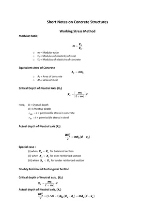
Modular Ratio
S
C
E
m
E
=
o m = Modular ratio
o ES = Modulus of elasticity of steel
o EC = Modulus of elasticity of concrete
Equivalent Area of Concrete
C S
A mA
=
o AC = Area of concrete
o AS = Area of steel
Critical Depth of Neutral Axis (XC)
C
mc
X d
t mc
æ ö
÷
ç
= ÷
ç ÷
÷
ç
è ø
+
Here, D = Overall depth
d = Efffective depth
cbc
s = c = permissible stress in concrete
st
s = t = permissible stress in steel
Actual depth of Neutral axis (Xa)
2
( )
2
a
st a
BX
mA d x
= -
Special case :
(i) when a c
X X
= for balanced section
(ii) when a c
X X
> for over reinforced section
(iii) when a c
X X
< for under reinforced section
Doubly Reinforced Rectangular Section
Critical depth of Neutral axis, (XC)
C
mc
X d
t mc
= ⋅
+
Actual depth of Neutral axis, (Xa)
2
(1.5 1) ( ) ( )
2
a
SC a c st a
bX
m A X d mA d x
+ - - = -
2. Singly Reinforced T‐Section
Effective width of flange
For beam casted monolithic with slab
0
1 2
6
6
2 2
w f
f
w
l
b d
B Minimum or
l l
b
ìæ ö
ï ÷
ïç ÷
+ +
ïç ÷
ç
ï ÷
ç
è ø
ï
ï
ï
ï
= í
ï
ï
ï
ï + +
ï
ï
ï
ï
î
For isolated T‐beam
0
0
4
f w
l
B b
l
B
= +
æ ö
÷
ç + ÷
ç ÷
ç ÷
è ø
l0 = Distance between points of zero moments in the beam
B = Total width of flange
bw = Width of web
Critical depth of Neutral axis (Xc)
C
mc
X d
t mc
æ ö
÷
ç
= ÷
ç ÷
÷
ç
è ø
+
When Neutral axis is in flange area
o Actual depth of Neutral axis
2
( )
2
a
st a
BX
mA d X
= -
Here, Xa = Actual depth of Neutral axis
Moment of resistance (Mr)
When Neutral axis is in web area
For actual depth of neutral axis
3. Moment of resistance (Mr)
Limit State Method
Design stress strain curve at ultimate state
Design value of strength
o For concrete
0.67
0.45
1.5
ck
d ck
mc
f
f
f f
g
= = =
mc
g = Partial factor of safety for concrete = 1.5
fd = design value of strength
o For steel
0.87
1.15
y
d y
f
f f
= =
Singly Reinforced Beam
Limiting depth of neutral axis (xu, lim)
,lim
700
0.87 1100
u
y
x d
f
= ´
+
Actual depth of neutral axis (Xu)
0.87
0.36
y st
u
ck
f A
C T X
f b
= =
Lever arm = d – 0.42 Xu
Ultimate moment of resistance
0.36 ( 0.42 )
u ck u u
M f bX d X
= -
0.87 ( 0.42 )
u y st u
M f A d X
= -
Special cases
1. Under‐reinforced section : Xu < Xu,lim
0.36 ( 0.42 )
u ck u u
M f bX d X
= -
0.87 ( 0.42 )
u y st u
M f A d X
= -
2. Balanced section: Xu = Xu,lim
,lim ,lim
0.36 ( 0.42 )
u ck u u
M f bX d X
= -
,lim
0.87 ( 0.42 )
u y st u
M f A d X
= -
3. Over reinforced section : Xu > Xu,lim
Xu limited to Xu,lim
Moment of resistance limited to (Mu,lim)
Doubly Reinforced Section
4. Limiting depth of neutral axis
,lim
700
0.87 1100
u
y
X d
f
= ´
+
For actual depth of neutral axis (Xu)
1 2
0.36 ( 0.45 ) 0.87
ck u sc ck sc y st
C T C C T
f bX f f A f A
= + =
+ - =
Ultimate moment of resistance
0.36 ( 0.42 ) ( 0.45 ) ( )
u ck u u sc ck sc C
M f bX d X f f A d d
= - + - -
fSC = stress in compression
T‐Beam
Limiting depth of neutral axis
,lim
700
0.87 1100
u
y
X d
f
= ´
+
Singly reinforced T‐Beam
o When NA is in flange area
Xu < Df
o
0.87
0.36
y st
u f
ck f
f A
X D
f b
= <
o Ultimate moment of resistance
0.36 ( 0.42 ) 0.87 ( 0.42 )
u ck f u u u y st u
M f b X d X or M f A d X
= - = -
o When NA is in web area
Xu > Df
Xu > Df and
3
7
f u
D X
<
For actual depth of neutral axis
0.36 0.45 ( ) 0.87
ck w u ck f w f y st
f b x f b b D f A
+ - =
Ultimate moment of resistance
0.36 ( 0.42 ) 0.45 ( )
2
f
u ck w u u ck f w f
D
M f b x d x f b b D d
æ ö
÷
ç
= - + - - ÷
ç ÷
ç ÷
è ø
1 2
0.87 ( 0.42 ) 0.87
2
f
u y st u y st
D
M f A d x f A d
æ ö
÷
ç
= - + - ÷
ç ÷
ç ÷
è ø
1 2
0.36 0.45 ( )
,
0.87 0.87
ck w u ck f w f
st st
y y
f b x f b b D
A A
f f
-
= =
When Xu > Df and
3
7
f u
D X
>
5. 0.15 0.65
f u f f
y X D D
= + <
For actual depth of neutral axis
1 2
0.36 0.45 ( ) 0.87 0.87
ck w u ck f w f y st y st
f b X f b b y f A f A
+ - = +
0.36 0.45 ( ) 0.87
ck w u ck f w f y st
f b X f b b y f A
+ - =
Design Beams and Slabs and Columns
Effective span
Simply supported beams and slabs (leff)
0
0
minimum
eff
l w
l
l d
ì +
ï
ï
= í
ï +
ï
î
Here, l0 = clear span
w = width of support
d = depth of beam or slab
For continuous beam
If width of support
1
12
< of clear span
0
0
minimum
eff
l w
l
l d
ì +
ï
ï
= í
ï +
ï
î
If width of support
1
12
> of clear span
o When one end fixed other end continuous or both end continuous.
leff = l0
o When one end continuous and other end simply supported
6. 0
0
/ 2
minimum
/ 2
eff
l w
l
l d
ì +
ï
ï
= í
ï +
ï
î
Cantilever
0
2
eff
d
l l
= +
0
2
eff
w
l l
æ ö
÷
ç
= + ÷
ç ÷
ç ÷
è ø
Frames
leff = Centre to centre distance
Support Condition Span/overall depth
Mild Steel Fe 415/Fe 500
Simply supported
Continuous
35
40
28
32
Slenderness limit
For simply supported or continuous beams
2
0
60
/ minimum
250
b
l b
d
ì
ï
ï
ï
ï
> í
ï
ï
ï
ï
î
l0 = Clear span
b = Width of the section
d = Effective depth
For cantilever beam
7. 2
0
25
/ minimum
100
b
l b
d
ì
ï
ï
ï
ï
> í
ï
ï
ï
ï
î
o Minimum tension reinforcement
0.85
st
y
A
bd f
=
o Maximum tension reinforcement = 0.04 bD
o Maximum compression reinforcement = 0.04 bD
where, D = overall depth of the section
o Nominal cover for different members
Beams 25 mm
Slab 20 to 30 mm
Column 40 mm
Foundations 50 mm
One way slab
2
y
x
l
l
>
ly = length of longer span
lx = length of shorter span
Columns
Working Stress Method
Slenderness ratio
dim
effective length
least lateral ension
l =
If 12
l > then the column is long.
Load carrying capacity for short column
sc sc cc c
P A A
s s
= +
AC = Area of concrete, C g SC
A A A
= -
SC
s = Stress in compression steel
CC
s = Stress in concrete
g
A = Total gross cross‐sectional area
SC
A = Area of compression steel
Load carrying capacity for long column
( )
r SC SC CC C
P C A A
s s
= +
Cr = Reduction factor
1.25
48
eff
r
l
C
B
= -
or
min
1.25
160
eff
r
l
C
i
= -
8. Effective length of Compression Members
Degree of End
Restraint of
compression
members
Symbol Theoretical value of
Effective Length
Recommended value
of Effective Length
(i) (ii) (iii) (iv)
Effectively held in
position and
restrained against
rotation in both ends
0.50 l 0.65 l
Effectively held in
position at both ends,
restrained against
rotation at one end
0.70 l 0.80 l
Effectively held in
position at both ends,
but not restrained
against rotation
1.00 l 1.00 l
Effectively held in
position and
restrained against
rotation at one end,
and at the other
restrained against
rotation but not held
in position
1.00 l 1.20 l
Effective held in
position and
restrained against
rotation in one end,
and at the other
partially restrained
against rotation but
not held in position
___ 1.50 l
Effectively held in
position at one end
but not restrained
against rotation, and
at the other end
restrained against
rotation but not held
in position
2.00 l 2.00 l
9. Effectively held in
position and
restrained against
rotation at one end
but not held in
position nor restrained
against rotation at the
other end.
2.00 l 2.00 l
Column with helical reinforcement
o 1.05( )
SC SC CC C
P A A
s s
= + for short column
o 1.05 ( )
r SC SC CC C
P C A A
s s
= + for long column
Longitudinal reinforcement
o Minimum area of steel = 0.8% of the gross area of column
o Maximum area of steel
When bars are not lapped Amax = 6% of the gross area of
column
When bars are lapped Amax = 4% of the gross area of column
Transverse reinforcement (Ties)
1
max 4
6
main
imum
mm
f
f
ì
ï
ï ⋅
ï
ï
= í
ï
ï
ï
ï
î
main
f = dia of main logitudnal bar
f = dia of bar for transverse reinforcement
Pitch (p)
min
leastlateraldimension
minimum 16
300 mm
f f
ì
ï
ï
ï
ï
= í
ï
ï
ï
ï
î
Helical reinforcement
o Diameters of helical reinforcement is selected such that
0.36 1
g ck h
C y C
A f V
A f V
é ù
ê ú
- £
ê ú
ë û
o
2
1000
( ) ( )
4
h h h
V d
P
p
p f
æ ö
÷
ç
= ÷
ç ÷
ç ÷
è ø
2
( )
4
C C
A d
p
=
1
C C
V A
= ´
dh = centre to centre dia of helix
= dg – 2 clear cover ‐ h
h
f = diameter of the steel bar forming the helix
10. Concentrically Loaded Columns
e = 0 ‐ column is truly axially loaded.
P 0.45 0.75
u ck c y SC
f A f A
= +
Bond, Anchorage and Development Length
Bond stress ( )
bd
t
bd
V
pjd
t =
å
V = Shear force at any section
d = Effective depth of the section
p
å = Sum of all perimeter of reinforcement
= ( )
n p f
⋅
n = Number of reinforcement
f = diameter of reinforcement
Development Length (Ld)
4
st
d
bd
L
fs
t
=
⋅
For WSM
0.87
4
y
d
bd
f
L
f
t
⋅
=
⋅
For LSM
Shear stress
For Homogeneous beam
V
q AY
lb
= ⋅
q = shear stress at any section
V = shear force at any section
AY = Moment of area of section above the point of consideration
I = Moment of inertia of section
3
12
bD
=
For Reinforced concrete beam
o Shear stress above NA
2 2
( )
2
a
V
q x y
l
= ⋅ -
2
max
2
a
V
q x
l
= ⋅ at y = 0
o Shear stress below NA
11. V
q
bjd
=
Nominal shear stress
V
V
bd
t =
Minimum shear reinforcement
o For WSM and LSM
o
0.4
0.87
SV
V y
A
bS f
³
o
2.175 y SV
V
f A
S
b
£
ASV = Area of shear reinforcement
SV = Spacing for shear reinforcement
Spacing of shear reinforcement
o
2.175 y SV
V
f A
S
b
=
Inclined stirrups
(sin cos )
S SV SV
V
d
V A
S
s a a
æ ö
÷
ç ÷
= ⋅ ⋅ + ç ÷
ç ÷
÷
ç
è ø
for WSM
(0.87 )(sin cos )
Su SV y
V
d
V A f
S
a a
æ ö
÷
ç ÷
= ⋅ + ç ÷
ç ÷
÷
ç
è ø
LSM
Pre‐stress Concrete
Analysis of prestress and Bending stress
Stress concept Method
Beam provided with a concentric tendon :
o Direct compressive force :
a
P
f
A
=
.
o Extreme stresses due to bending moment alone :
0
M
f
Z
=
o Stress at the extreme top edge :
P M
A Z
+
o Stress at the extreme bottom edge :
P M
A Z
-
Beams with eccentrics tendon :
12. Direct stresses due to prestressing force:
P
A
+
Extreme stresses due to eccentricity of the prestressing force :
.
P e
Z
Extreme stresses due to bending moment :
M
Z
Stress at top fiber
.
P P e M
A Z Z
= - +
Stress at bottom fibre
.
P P e M
A Z Z
= + -
Strength Concept method
If the beam is subjected to a bending moment M, then the C‐line will be
shifted from the P‐line by a distance 'a' called lever arm.
M M
a
P C
= =
Extreme stresses in concrete are given by
C C eccentricity of C
A Z
´
=
Load Balancing Concept
Axial longitudinal force provided by the tendon =
cos
P q = P {since q is small}
Direct stress on the section
cos
P P
A A
q
= =
Net Bending Moment
2
( 2 sin )
4 8
W P l wl
M
q
-
= +
Losses of Pre‐stress
Types of Losses Losses in pre‐tensioned
member
Losses in posttensioned
member
1. Loss of pre‐stress during
tensioning process due to
friction.
(a) Loss due to length effect
(b) Loss due to curvature effect
No Loss
No Loss
P0kx
0
P ma
13. (c) Loss due to both length and
curvature effect
No Loss
0( )
P kx ma
+
Here,
P0 = Pre‐stressing force at the
jacking end
K = Wobble friction factor
15 x 10‐4
per meter < K < 50 x 10‐
4
per meter.
= Cumulative angle in radians
through which tangent to the
cable profile has turned
between any two points under
consideration.
= Coefficient of friction in
curves
= 0.25 to 0.55
2. Loss of pre‐stress at the
anchoring stage
No Loss
S
l
E
l
D
⋅
Here,
l
D = effective slip of the wire.
l = Length of the tendon.
ES = Young's modulus for
tendon wires
3. Loss of pre‐stress occurring
Sub‐sequently
(a) Loss of stress due to
shrinkage of concrete
(b) Loss of stress due to creep
to concrete
(c) Loss of stress due to elastic
shortening of concrete
4
(3 10 ) S
E
-
´
Here,
ES = Young’s modulus for
tendon wire
C
m f
f ⋅ ⋅
Here,
m = Modular ratio
= ES/EC
fC = Original pre‐stress in
concrete at the level of steel
C
m f
⋅
Here
4
10
2 10
log ( 2)
S
E
T
´
⋅
+
Here
T = Age of concrete at the time
of transfer of stress (in days)
C
m f
f ⋅ ⋅
zero
it all the bars are tensioned at
same time
14. (d) Loss of stress due to creep
of steel or loss due to stress
relaxations.
C
f = Initial stress in concrete at
the level of steel.
1 to 5% of initial pre‐stress.
S
l
E
l
D
⋅ for subsequent
tensioning
1 to 5% of initial pre‐stress